Intesis 700 Series User manual
IN701-KNX Series
INTESIS PROTOCOL TRANSLATOR WITH KNX, SERIAL, AND IP SUPPORT
USER MANUAL
Version 1.2
Publicaon date 2023-01-09
ENGLISH

Copyright © 2022 Intesis
Disclaimer
The informaon in this document is for informaonal purposes only. Please inform HMS Networks of any
inaccuracies or omissions found in this document. HMS Networks disclaims any responsibility or liability for any
errors that may appear in this document.
HMS Networks reserves the right to modify its products in line with its policy of connuous product
development. The informaon in this document shall therefore not be construed as a commitment on the
part of HMS Networks and is subject to change without noce. HMS Networks makes no commitment to update
or keep current the informaon in this document.
The data, examples and illustraons found in this document are included for illustrave purposes and are only
intended to help improve understanding of the funconality and handling of the product. In view of the wide
range of possible applicaons of the product, and because of the many variables and requirements associated
with any parcular implementaon, HMS Networks cannot assume responsibility or liability for actual use
based on the data, examples or illustraons included in this document nor for any damages incurred during
installaon of the product. Those responsible for the use of the product must acquire sucient knowledge in
order to ensure that the product is used correctly in their specic applicaon and that the applicaon meets all
performance and safety requirements including any applicable laws, regulaons, codes and standards. Further,
HMS Networks will under no circumstances assume liability or responsibility for any problems that may arise as
a result from the use of undocumented features or funconal side eects found outside the documented scope
of the product. The eects caused by any direct or indirect use of such aspects of the product are undened and
may include e.g. compability issues and stability issues.

Table of Contents
1. Order Codes ........................................................................................................................... 1
2. General Informaon ................................................................................................................ 2
2.1. Intended Use of the User Manual ........................................................................................ 2
2.2. General Safety Informaon ................................................................................................ 2
2.3. Admonion Messages and Symbols ..................................................................................... 2
3. General Introducon ................................................................................................................ 4
4. Modbus Server to KNX ............................................................................................................. 5
4.1. Specic Introducon ......................................................................................................... 5
4.2. Funconality ................................................................................................................... 5
5. KNX to Modbus Client .............................................................................................................. 6
5.1. Specic Introducon ......................................................................................................... 6
5.2. Funconality ................................................................................................................... 6
6. BACnet Server to KNX .............................................................................................................. 8
6.1. Specic Introducon ......................................................................................................... 8
6.2. Funconality ................................................................................................................... 8
7. KNX to BACnet Client .............................................................................................................. 10
7.1. Specic Introducon ........................................................................................................ 10
7.2. Funconality .................................................................................................................. 10
8. ASCII Server to KNX ................................................................................................................ 11
8.1. Specic Introducon ........................................................................................................ 11
8.2. Funconality .................................................................................................................. 11
9. Gateway Capacity ................................................................................................................... 13
10. KNX Interface ....................................................................................................................... 14
10.1. Descripon ................................................................................................................... 14
10.2. Points Denion ............................................................................................................ 14
11. Modbus Interface ................................................................................................................. 15
11.1. General Descripon ....................................................................................................... 15
11.2. Modbus Server Interface ................................................................................................. 15
11.2.1. Descripon ........................................................................................................... 15
11.2.2. Funcons Supported ............................................................................................... 15
11.2.3. Modbus RTU ......................................................................................................... 16
11.2.4. Modbus TCP .......................................................................................................... 16
11.2.5. Modbus Server Interface Points Denion .................................................................. 17
11.3. Modbus Client Interface .................................................................................................. 17
11.3.1. Descripon ........................................................................................................... 17
11.3.2. Points Denion .................................................................................................... 18
12. BACnet Interface .................................................................................................................. 19
12.1. General Descripon ....................................................................................................... 19
12.2. BACnet Client ................................................................................................................ 20
12.2.1. Descripon ........................................................................................................... 20
12.2.2. Points Denion .................................................................................................... 21
12.3. BACnet Server ............................................................................................................... 22
IN701-KNX Series
USER MANUAL Version 1.2

12.3.1. Descripon ........................................................................................................... 22
12.3.2. BACnet IP ............................................................................................................. 23
12.3.3. BACnet MSTP ........................................................................................................ 23
13. ASCII Interface ..................................................................................................................... 24
13.1. Descripon ................................................................................................................... 24
13.2. ASCII Serial ................................................................................................................... 24
13.3. ASCII TCP ...................................................................................................................... 24
13.4. Address Map ................................................................................................................ 24
13.5. Points Denion ............................................................................................................ 25
13.6. Messages ..................................................................................................................... 26
14. Mounng ............................................................................................................................ 27
15. Connecons ......................................................................................................................... 28
15.1. Power Supply ................................................................................................................ 29
15.2. Connecon Diagrams for each Applicaon .......................................................................... 30
15.3. Connecon to KNX ......................................................................................................... 35
15.4. Connecon to BACnet .................................................................................................... 35
15.5. Connecon to Modbus ................................................................................................... 36
15.6. Connecon to ASCII ........................................................................................................ 37
15.7. Console and USB Connecons .......................................................................................... 38
16. Set-up Process with the Conguraon Tool ............................................................................... 39
16.1. Prerequisites ................................................................................................................. 39
16.2. Intesis MAPS: Conguraon and Monitoring Tool ................................................................. 39
16.2.1. Introducon .......................................................................................................... 39
16.2.2. Template Selecon ................................................................................................. 40
16.2.3. Connecon Tab ...................................................................................................... 40
16.2.4. Conguraon Tab ................................................................................................... 41
16.2.5. Signals Tab ............................................................................................................ 41
16.2.6. Receive/Send Tab ................................................................................................... 41
16.2.7. Diagnosc ............................................................................................................. 42
17. Technical Specicaons ......................................................................................................... 43
18. Dimensions .......................................................................................................................... 44
IN701-KNX Series
USER MANUAL Version 1.2
1. Order Codes
ORDER CODE LEGACY ORDER CODE
IN701KNX1000000 INMBSKNX1000000 INKNXMBM1000000 INBACKNX1000000 INKNXBAC1000000 -
IN701KNX2500000 INMBSKNX2500000 INKNXMBM2500000 INBACKNX2500000 INKNXBAC2500000 -
IN701KNX6000000 INMBSKNX6000000 INKNXMBM6000000 INBACKNX6000000 INKNXBAC6000000 INASCKNX6000000
IN701KNX1K20000 INMBSKNX1K20000 INKNXMBM1K20000 INBACKNX1K20000 INKNXBAC1K20000 -
IN701KNX3K00000 INMBSKNX3K00000 INKNXMBM3K00000 INBACKNX3K00000 INKNXBAC3K00000 INASCKNX3K00000
PRODUCT NAME ORDER CODE DESCRIPTION INTESIS MAPS TEMPLATE APPLICATION
IN701-KNX IN701KNXxxx*0000
Intesis Protocol Translator
with KNX, Serial, and IP
Support
IN-MBS-KNX KNX to Modbus server
IN-KNX-MBM Modbus client to KNX
IN-BAC-KNX KNX to BACnet server
IN-KNX-BAC BACnet client to KNX
IN-ASCII-KNX KNX to ASCII server
*xxx denes the Intesis gateway capacity.
Order Codes IN701-KNX Series
USER MANUAL Version 1.2 Page 1 of 44
2. General Informaon
2.1. Intended Use of the User Manual
This manual contains the main features of this Intesis gateway and the instrucons for its appropriate
installaon, conguraon, and operaon.
The contents of this manual should be brought to the aenon of any person who installs, congures, or
operates this gateway or any associated equipment.
Keep this manual for future reference during the installaon, conguraon, and operaon.
2.2. General Safety Informaon
IMPORTANT
Follow these instrucons carefully. Improper work may seriously harm your health and damage the
gateway and/or any other equipment connected to it.
Only technical personnel, following these instrucons and the country legislaon for installing electric
equipment, can install and manipulate this gateway.
Install this gateway indoors, in a restricted access locaon, avoiding exposure to direct solar radiaon, water, high
relave humidity, or dust.
All wires (for communicaon and power supply, if needed) must only be connected to networks with indoor
wiring. All communicaon ports are considered for indoor use and must only be connected to SELV circuits.
Disconnect power wires before manipulang and connecng them to the gateway.
Use SELV-rated NEC class 2 or limited power source (LPS) power supply.
Supply always a correct voltage to power the gateway. See Technical Specicaons (page 43).
Respect the expected polarity of power and communicaon cables when connecng them to the gateway.
CAUTION
Only an authorized installer is allowed to replace the baery. There's a risk of explosion if the baery
is replaced by an incorrect type. Dispose of used baeries according to local legislaon.
Safety instrucons in other languages can be found at hps://intesis.com/docs/manuals/v6-safety
2.3. Admonion Messages and Symbols
DANGER
Instrucons that must be followed to avoid an imminently hazardous situaon that, if not avoided,
will result in death or severe injury.
WARNING
Instrucons that must be followed to avoid a potenally hazardous situaon that, if not avoided,
could result in death or severe injury.
IN701-KNX Series General Informaon
Page 2 of 44 USER MANUAL Version 1.2
CAUTION
Instrucon that must be followed to avoid a potenally hazardous situaon that, if not avoided,
could result in minor or moderate injury.
IMPORTANT
Instrucon that must be followed to avoid a risk of reduced funconality and/or damage to the
equipment or to avoid a network security risk.
NOTE
Addional informaon which may facilitate installaon and/or operaon.
TIP
Helpful advice and suggesons.
NOTICE
Remarkable Informaon.
Admonion Messages and Symbols IN701-KNX Series
USER MANUAL Version 1.2 Page 3 of 44
3. General Introducon
This Intesis® gateway allows you to integrate Serial and IP protocols to KNX easily.
This document describes the available applicaons for this gateway:
• KNX TP to Modbus® TCP & RTU Server
• Modbus TCP & RTU Client to KNX TP
• KNX TP to BACnet®/IP & MSTP Server
• BACnet/IP & MSTP Client to KNX TP
• KNX TP to ASCII IP & Serial Server
IMPORTANT
This document assumes that the user is familiar with KNX, BACnet, Modbus, and ASCII technologies
and their technical terms.
NOTE
Some secons provide general informaon common to all applicaons, while others highlight
specic dierences, capacies, or limitaons.
In general terms, you must have a KNX installaon or device on one side and a BACnet, Modbus, or ASCII
installaon or device on the other side (only one at a me).
IMPORTANT
The Intesis gateway can act as a server or client for BACnet and Modbus but only as a server for
ASCII.
As always, the conguraon process is fast and easy:
1. Launch the conguraon tool.
2. Select the template.
3. Connect the Intesis gateway to the PC.
4. Adjust the conguraon and signals to your project.
5. Send the conguraon to the gateway.
And you are ready to go!
IN701-KNX Series General Introducon
Page 4 of 44 USER MANUAL Version 1.2
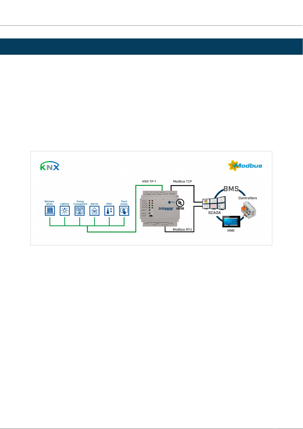
4. Modbus Server to KNX
4.1. Specic Introducon
This secon describes the integraon of KNX systems into Modbus RTU and/or Modbus TCP systems using the
Modbus server to KNX applicaon of the Intesis gateway.
This integraon allows a Modbus control system to access the groups, objects, and associated devices of KNX
systems as if they were part of the Modbus system itself and vice versa.
The gateway acts as a Modbus TCP or RTU server device in its Modbus interface, allowing read/write points from
the Modbus client devices, and oering these points' values through its KNX interface, acng as one more KNX
device of the system.
The gateway conguraon is carried out through the conguraon tool.
Figure 1. Integraon of KNX TP devices into Modbus RTU or Modbus TCP control and monitor systems
4.2. Funconality
From the KNX system point of view, aer starng the gateway or performing a KNX bus reset, the Intesis gateway
polls the KNX signals and stores the received values in its memory, ready to be served to the Modbus system
when requested. It also listens for any KNX telegram related to the internal points congured in it and acts
accordingly to the conguraon of the related points.
From the Modbus system point of view, aer starng it, the gateway listens for any read or write request, serves
any read request, or performs any wring request of its internal points received from the Modbus system. The
values received from Modbus become available to be read by the KNX system and vice versa.
In the gateway, each Modbus point is associated with a KNX group address so that the KNX system sees
the whole Modbus system as if it was one more KNX device with the same conguraon and operaon
characteriscs.
When a Modbus point changes, the gateway sends a write telegram to the associated group address in the KNX
bus.
When the gateway receives a telegram from a KNX group address associated with a Modbus point, it sends a
message to the corresponding Modbus device to perform the related acon.
Modbus Server to KNX IN701-KNX Series
USER MANUAL Version 1.2 Page 5 of 44
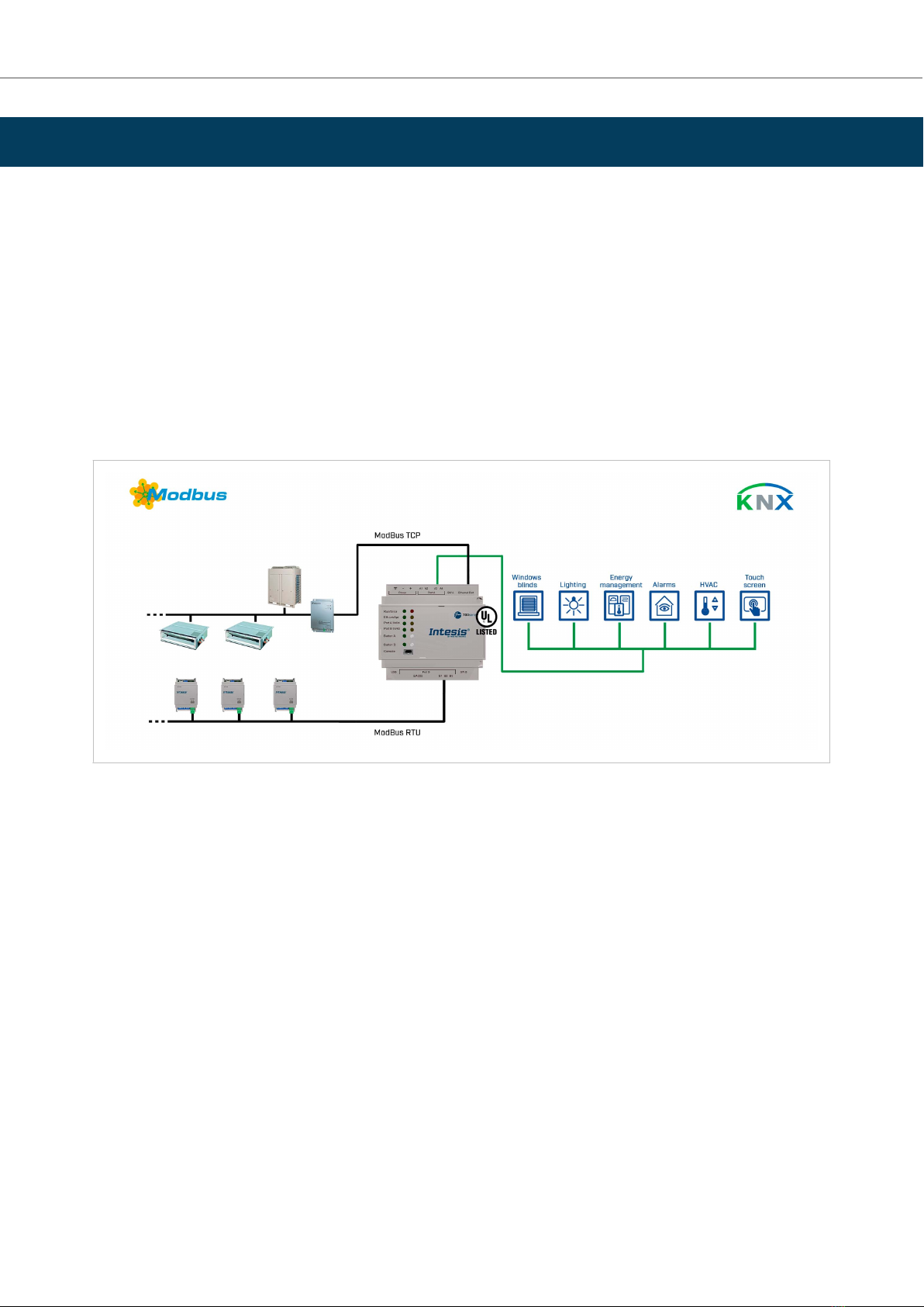
5. KNX to Modbus Client
5.1. Specic Introducon
This secon describes the integraon of Modbus RTU installaons into KNX systems using the KNX to Modbus
client applicaon of the Intesis gateway.
This integraon allows a KNX control system or device to access the signals and resources of Modbus systems as
if they were part of the KNX system and vice versa.
The gateway acts as a Modbus RTU client device in its Modbus interface, reading/wring points from the
Modbus server devices by automac connuous polling. The gateway oers these points' values through its KNX
interface, acng as one more KNX device of the system.
The gateway conguraon is carried out through the conguraon tool.
Figure 2. Integraon of Modbus RTU or TCP devices into KNX control and monitoring systems
5.2. Funconality
From the Modbus system point of view, aer starng it, the Intesis gateway connuously reads the Modbus RTU
service devices, updang all the points' values received in its memory.
From the KNX system point of view, aer starng the gateway or performing a KNX bus reset, the Intesis gateway
polls the KNX signals and stores the received values in its memory, ready to be served to the Modbus system
when requested. It also listens for any KNX telegram related to the internal points congured in it and acts
accordingly to the conguraon of the related points.
In the gateway, each Modbus point is associated with a KNX group address so that the KNX system sees
the whole Modbus system as if it was one more KNX device with the same conguraon and operaon
characteriscs.
When a Modbus point changes, the gateway sends a write telegram to the associated group address in the KNX
bus.
When the gateway receives a telegram from a KNX group address associated with a Modbus point, it sends a
message to the corresponding Modbus device to perform the related acon.
IN701-KNX Series KNX to Modbus Client
Page 6 of 44 USER MANUAL Version 1.2

When polling the Modbus devices, if a non-response is detected, the corresponding virtual signal inside the
gateway will be acvated to indicate the communicaon error as a KNX group address.
Funconality IN701-KNX Series
USER MANUAL Version 1.2 Page 7 of 44

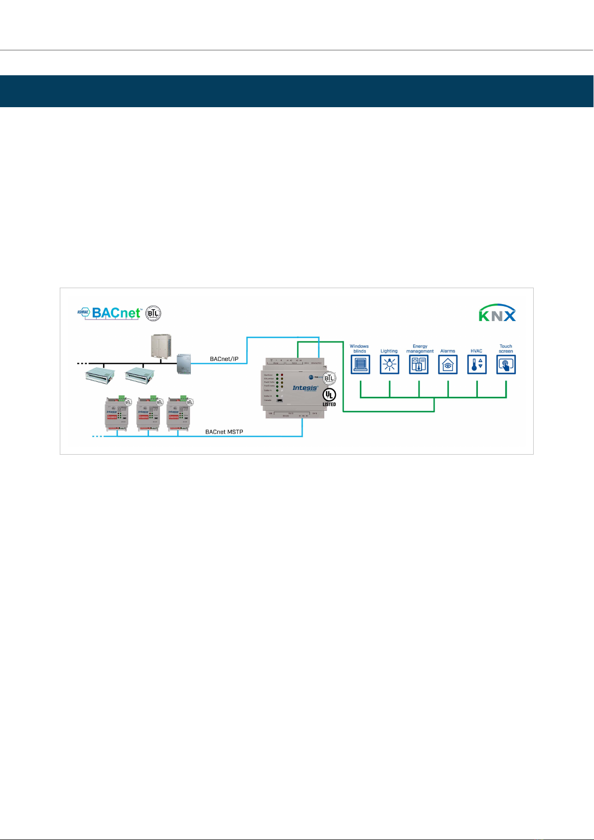
6. BACnet Server to KNX
6.1. Specic Introducon
This secon describes the integraon of KNX installaons into BACnet MSTP or BACnet IP compable devices and
systems using the BACnet server to KNX applicaon of the Intesis gateway.
This integraon allows a BACnet-based control system to access the signals and resources of KNX systems as if
they were part of the BACnet system itself and vice versa.
The gateway acts as a BACnet IP server or BACnet MSTP device in its BACnet interface, allowing other BACnet
devices to perform subscripon (COV) requests and readings/wrings to its internal points. From the KNX point
of view, the gateway emulates a KNX device.
The gateway conguraon is carried out through the conguraon tool.
Figure 3. Integraon of KNX devices into BACnet IP or BACnet MS/TP control and monitoring systems
6.2. Funconality
From the KNX system point of view, aer starng the gateway or performing a KNX bus reset, the Intesis gateway
polls the KNX signals and stores the received values in its memory, ready to be served to the BACnet system
when requested. It also listens for any KNX telegram related to the internal points congured in it and acts
accordingly to the conguraon of the related points.
From the BACnet system point of view, aer starng it, the gateway listens for any subscripon (COV) request,
serves any polling request, or performs any wring request of its internal points received from the BACnet
system. The values received from BACnet are immediately wrien in the associated KNX communicaon object if
allowed by the KNX sengs.
In the KNX part, one main group address and dierent listening group addresses can be dened for every point.
This way, every point can be addressed using its main group address and the other specied listening addresses.
Any change in a point in the gateway with the “T” ag acvated (in the KNX part) will force the transmission of
this point value with the corresponding telegram to the KNX system.
Any point with the “W” ag acvated (in the KNX part) can be wrien from the KNX system at any moment.
IN701-KNX Series BACnet Server to KNX
Page 8 of 44 USER MANUAL Version 1.2

Any point with the “R” ag acvated (in the KNX part) can be read from the KNX system at any moment.
Any point with the “Ri” ag acvated (in the KNX part) will be read aer every reset of the gateway.
Funconality IN701-KNX Series
USER MANUAL Version 1.2 Page 9 of 44
7. KNX to BACnet Client
7.1. Specic Introducon
This secon describes the integraon of BACnet MSTP and BACnet IP installaons into KNX systems using the
KNX to BACnet client applicaon of the Intesis gateway.
This integraon allows a KNX system to access the signals and resources of a BACnet system as if they were part
of the KNX system itself and vice versa.
From the BACnet point of view, the gateway acts as a BACnet client device, so it can subscribe (COV) or perform
periodic polling and wrings on congured BACnet objects. The BACnet points’ values are available through its
KNX interface, acng in the KNX system as one more KNX device.
The gateway conguraon is carried out through the conguraon tool.
Figure 4. Integraon of BACnet IP or MSTP devices into KNX control and monitoring systems
7.2. Funconality
From the BACnet system point of view, aer starng it, the gateway subscribes to congured BACnet points or
reads them connuously from their respecve BACnet server devices, updang in its memory the received value
of their Present_Value property.
Each Present_Value is associated with a KNX group object that, in turn, is associated with one or more KNX group
addresses.
When a KNX object changes, it is transmied to the KNX system with its corresponding group address.
Likewise, when a change is received in a write-enabled KNX group object, the change is wrien to the
Present_Value property of the corresponding BACnet object associated with it (using the WriteProperty BACnet
service).
Therefore, the Intesis gateway performs as a single KNX device in the KNX system, oering communicaon
objects to access the BACnet objects of the congured external BACnet devices.
When polling BACnet server devices, if a non-response is detected, the corresponding virtual signal inside the
gateway will be acvated to indicate the communicaon error to the KNX system as a KNX group object.
IN701-KNX Series KNX to BACnet Client
Page 10 of 44 USER MANUAL Version 1.2
8. ASCII Server to KNX
8.1. Specic Introducon
This secon describes the integraon of KNX installaons into ASCII serial (EIA-232 or EIA-485) or ASCII IP
compable devices and systems using the ASCII Server to KNX applicaon of the Intesis gateway.
This integraon aims to make KNX system signals and resources accessible from any programmable system
capable of reading/wring simple text messages through EIA-232 or EIA-485 serial port or Ethernet TCP/IP port
(for example, Extron, LiteTouch systems).
In its KNX interface, the Intesis gateway acts as a KNX device, reading/wring points from other KNX devices and
oering these points' values through its ASCII interface using simple ASCII messages.
The gateway conguraon is carried out through the conguraon tool.
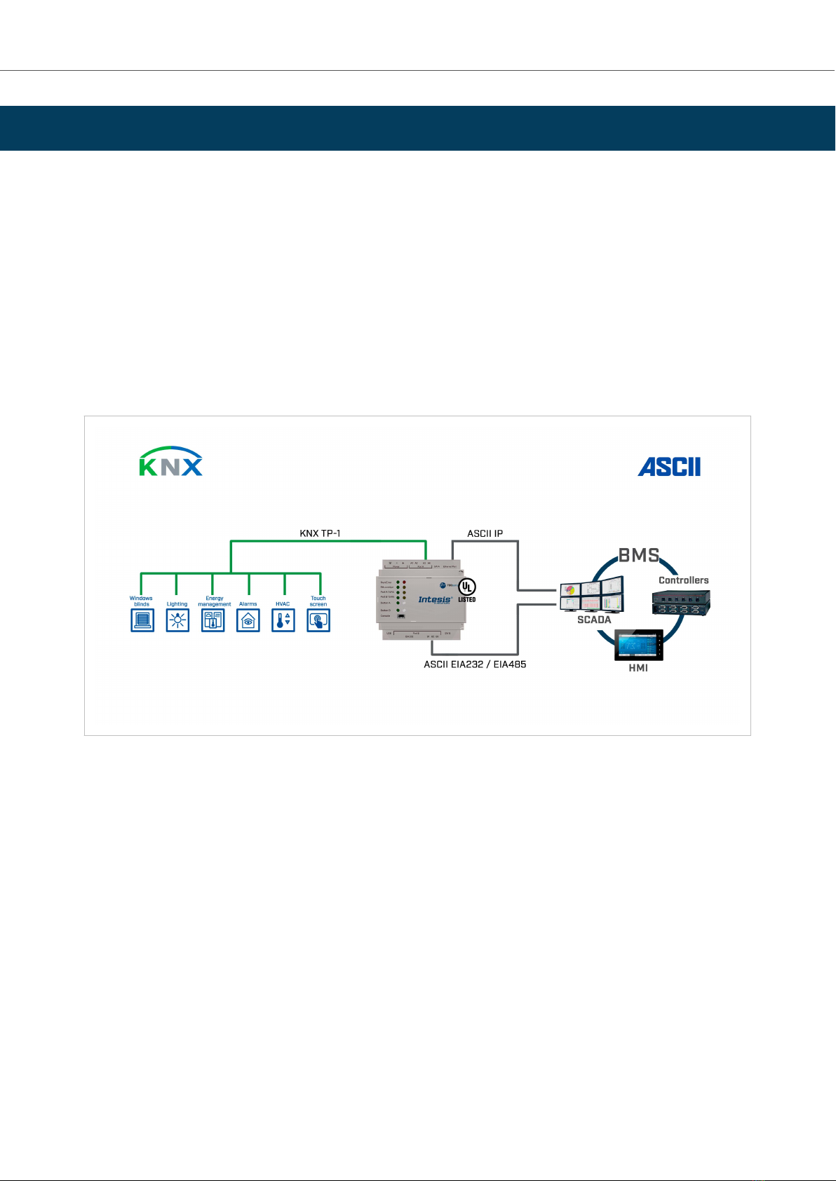
Figure 5. Integraon of KNX devices into ASCII IP or ASCII serial control and monitoring systems
8.2. Funconality
From the KNX system point of view, aer starng the gateway or performing a KNX bus reset, the Intesis gateway
polls the KNX signals and stores the received values in its memory, ready to be served to the ASCII system when
requested. It also listens for any KNX telegram related to its congured internal points and acts accordingly to the
conguraon of the related point.
From the ASCII system point of view, aer starng it, the gateway listens for any read or write request, serves any
read request, or performs any wring request of its internal points received from the ASCII system. The values
received from ASCII become available to be read by the KNX system and vice versa.
In the gateway, each ASCII point is associated with a KNX group address, so the KNX system sees the whole ASCII
system as if it was one more KNX device, with the same conguraon and operaon characteriscs.
When an ASCII point changes, the gateway sends a write telegram to the associated group address in the KNX
bus.
ASCII Server to KNX IN701-KNX Series
USER MANUAL Version 1.2 Page 11 of 44

When the gateway receives a telegram from a KNX group address associated with an ASCII point, it sends a
message to the corresponding ASCII device to perform the related acon.
IN701-KNX Series Funconality
Page 12 of 44 USER MANUAL Version 1.2
9. Gateway Capacity
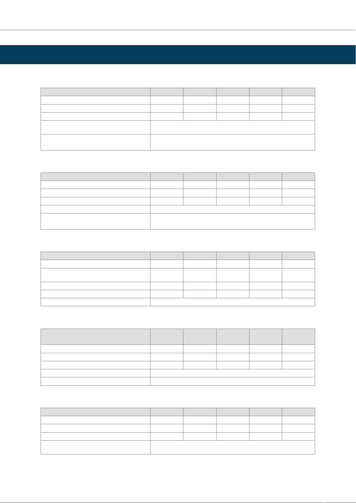
Table 1. For Modbus server to KNX
Element 100 version 250 version 600 version 1200 version 3000 version
Maximum number of KNX communicaon objects 100 250 600 1200 3000
Maximum number of KNX main group addresses 100 250 600 1200 3000
Maximum number of KNX associaons 200 500 1200 2400 6000
Type of Modbus client devices supported Those supporng Modbus protocol communicaon over TCP/IP and RTU (EIA-485 and
EIA-232)
Number of Modbus client devices supported One client device per RTU node
Up to 5 TCP connecons
Table 2. For KNX to Modbus Client
Element 100 version 250 version 600 version 1200 version 3000 version
Maximum number of KNX communicaon objects 100 250 600 1200 3000
Maximum number of KNX main group addresses 100 250 600 1200 3000
Maximum number of possible KNX associaons 200 500 1200 2400 6000
Type of Modbus server devices supported Those supporng Modbus protocol communicaon over TCP/IP and RTU (EIA-485)
Number of Modbus server devices supported Up to 255 Devices per Node (RTU and TCP)
Up to 5 TCP connecons
Table 3. For BACnet server to KNX
Element 100 version 250 version 600 version 1200 version 3000 version
Maximum number of BACnet objects 100 250 600 1200 3000
Maximum number of BACnet subscripons (COV)
requests
200 500 1200 2400 6000
Maximum number of KNX main group addresses 100 250 600 1200 3000
Maximum number of KNX associaons 200 500 1200 2400 6000
Type of BACnet devices supported Those supporng communicaon with BACnet IP and MS/TP
Table 4. For KNX to BACnet Client
Element 100
version
250
version
600
version
1200
version
3000
version
Maximum number of communicaon objects 100 250 600 1200 3000
Maximum number of main group addresses 100 250 600 1200 3000
Maximum number of KNX associaons 200 500 1200 2400 6000
Type of BACnet devices supported Those supporng communicaon with BACnet IP and MS/TP
Maximum number of BACnet devices 256
Table 5. For ASCII server to KNX
Element 100 version 250 version 600 version 1200 version 3000 version
Maximum number of KNX main group addresses 100 250 600 1200 3000
Maximum number of KNX associaons 200 500 1200 2400 6000
Maximum number of ASCII registers 100 250 600 1200 3000
ASCII link layers supported Those supporng communicaon with ASCII client with simple messages through a
TCP/IP or serial connecon (EIA-232 and EIA-485)
Gateway Capacity IN701-KNX Series
USER MANUAL Version 1.2 Page 13 of 44

10. KNX Interface
10.1. Descripon
The KNX interface of the gateway connects directly to the KNX bus performing as one more device in the KNX
system. In this way, the gateway can receive, manage, and send all telegrams related to its conguraon to the
KNX bus.
When the gateway receives write telegrams of KNX group addresses associated with internal datapoints, it sends
the corresponding messages to the internal system, keeping both systems synchronized at every moment.
When the gateway detects a change in a signal of the other side's protocol, it sends a write telegram to the KNX
bus (addressed with the group address associated with the corresponding group object), keeping both systems
synchronized at every moment.
Since the gateway connuously checks the KNX bus status, if a bus drop-down is detected, for example, due to a
failure in the bus power supply, once the KNX bus is restored, the gateway will send read telegrams to all group
objects marked with "Ri." The behavior of each point in the gateway is determined by the ags congured for the
point.
10.2. Points Denion
Every internal communicaon object has the following KNX properes:
Property Descripon
Descripon Descripve informaon about the communicaon object or signal.
Signal Signal descripon. Only for informave purposes (it facilitates the idencaon of the signal).
DPT KNX data type used to code the signal value. It will depend on the type of signal associated with the external system in every
case. In some integraons, it is selectable while, in others, it is xed due to the intrinsic characteriscs of the signal.
Group KNX group to which the point is associated. It is also the group to which the read (R), write (W), transmit (T), update (U), and
read on init (Ri) ags are applied. It is the sending group.
Addional
addresses
Addresses allowed to write on the group object, apart from the main group address.
RRead. If this ag is acvated, read telegrams of this group address will be accepted.
Ri Read on Init. If this ag is acvated, the object will trigger the corresponding read request (on the associated group address)
on inializaon.
WWrite. If this ag is acvated, write telegrams on this group object will be accepted.
TTransmit. If this ag is acvated, when the group object value changes due to a change in the external system, a write telegram
of the associated group address will be sent to the KNX bus.
UUpdate. If this ag is acvated, update telegrams (response to read telegrams) on this group object will be accepted.
Acve If acvated, the point will be acve in the Intesis gateway; if not, its behavior will be as if it was not dened. This property
allows deacvang points without deleng them, keeping them for future use if needed.
IN701-KNX Series KNX Interface
Page 14 of 44 USER MANUAL Version 1.2
11. Modbus Interface
11.1. General Descripon
The Modbus protocol is an applicaon-layer messaging protocol developed by Modicon in 1979. It is used to
establish master-slave/client-server communicaon between intelligent devices over dierent types of buses or
networks. The Intesis gateway supports Modbus TCP and RTU.
Modbus is a request/reply protocol and oers services specied by funcon codes. Modbus funcon codes are
elements of Modbus request/reply PDUs (Protocol Data Unit).
11.2. Modbus Server Interface
11.2.1. Descripon
The gateway acts as a server device in its Modbus interface, which can be:
• The Ethernet port for Modbus TCP.
• The EIA-485/EIA-232 ports for Modbus RTU.
NOTICE
Modbus RTU and TCP modes can be acve in the gateway one at a me or both simultaneously.
To access the gateway's points and resources from a Modbus client device, you must specify as Modbus register
addresses those congured inside the gateway corresponding to the signals on the eld device protocol.
11.2.2. Funcons Supported
NOTICE
This part is common for both Modbus TCP and Modbus RTU.
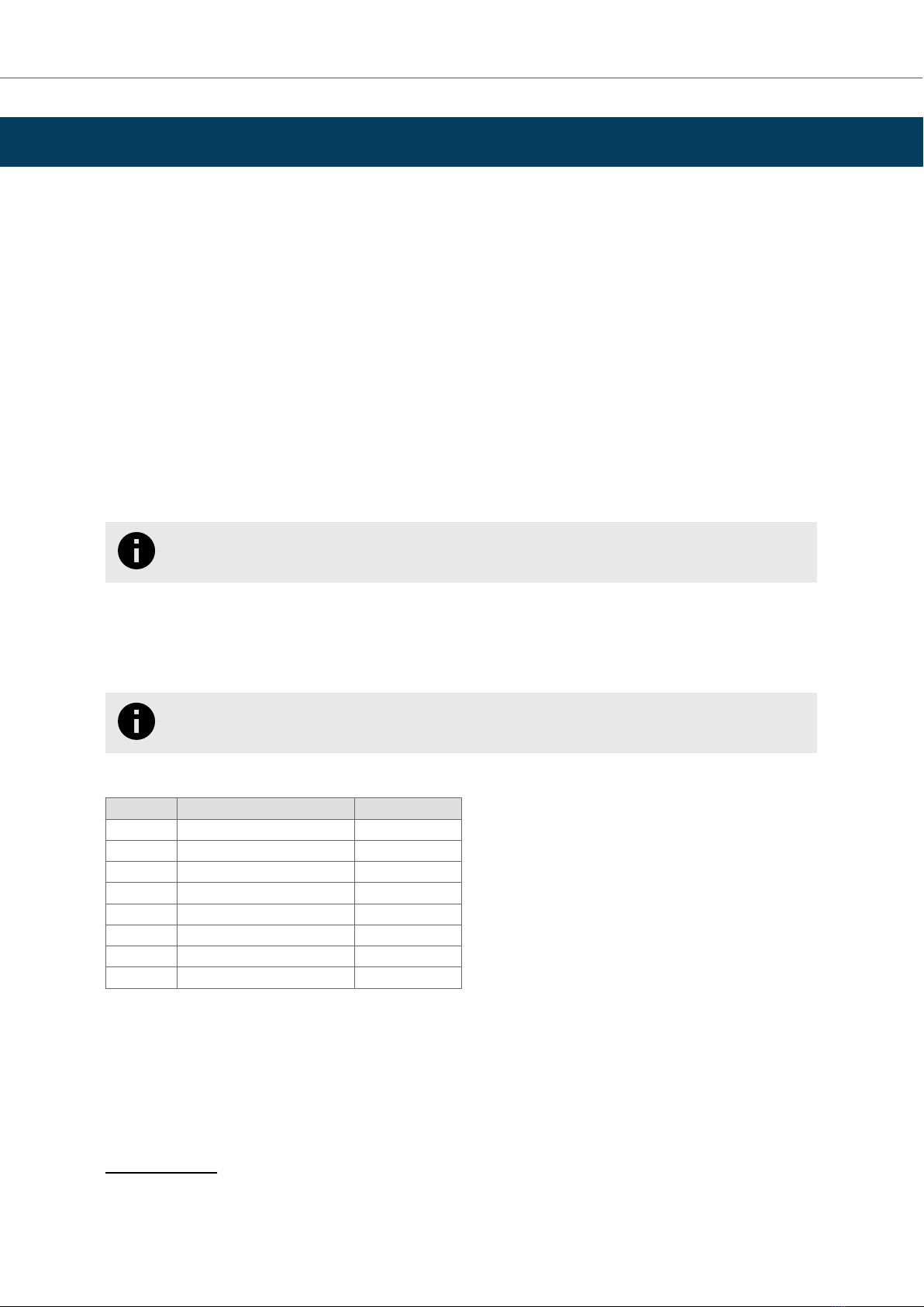
Table 6. Modbus funcons
#Funcon Read/Write
01 Read Coils R
02 Read Discrete Inputs R
03 Read Holding Registers R
04 Read Input Registers R
05 Write Single Coil W
06 Write Single Register W
15 Write Mulple Coils W
16 Write Mulple Registers W
If poll records are used to read or write more than one register, the range of addresses requested must contain
valid addresses; if not, the Intesis gateway will return the corresponding Modbus error code.
All registers are of 2 bytes, even if they are associated with signals of bit type on theKNX side. Its content is
expressed in MSB .. LSB.1
Modbus error codes are fully supported. They are sent whenever a non-valid Modbus acon or address is
required.
1MSB: most signicant bit; LSB: less signicant bit
Modbus Interface IN701-KNX Series
USER MANUAL Version 1.2 Page 15 of 44

11.2.3. Modbus RTU
Using the conguraon tool, you can set these parameters:
• Baud rate: 1200, 2400, 4800, 9600, 19200, 38400, 56700 and 115200 bps
• Data Bits: 8 bits
• Parity: none, even, or odd
• Stop Bits: 1 and 2 bits
• Modbus server address
• Physical connecon (EIA-232 or EIA-485)
IMPORTANT
• EIA-232 connector uses RX, TX, and GND lines.
• EIA-485 connector uses B-, A+, and SNGD.
11.2.4. Modbus TCP
Modbus TCP communicaon is characterized basically by the embedding of the Modbus RTU protocol into
TCP/IP frames, which allows faster communicaon and a longer distance between client and server devices in
comparison with RTU communicaon over a serial line. Another benet is using common TCP/IP infrastructure in
buildings and transming over WAN or the internet. It also allows the coexistence of one or more clients and, of
course, one or more server devices in a given network, all interconnected through a TCP/IP-based network.
Use the conguraon tool to congure the IP sengs of the gateway (DHCP status, own IP, netmask, and default
gateway) and the TCP port.
NOTE
The default port is 502.
IN701-KNX Series Modbus Server Interface
Page 16 of 44 USER MANUAL Version 1.2
This manual suits for next models
6
Table of contents
Other Intesis Electronic Dictionary manuals


