UNBOXING
• The Translator has removable top and bottom frontplastics to cover screw housings.
• The Translator is housed in an IP Rated box, with knockouts for IP rated glands.
• 4 plastic screws are provided to secure the lid.
For more information, please refer to the complete product manual.
IMPORTANT TO CONSIDER
When mounting a wireless device a comprehensive radio survey
should have been carried out to establish the location that provides
the best coverage and optimum reach. Taking into consideration the building
structure and materials, the survey identifies the wireless infrastructure
required and product locations for optimum performance, identifying
any factor that could prevent radio integrity.
Avoid fixing or mounting the unit close to the following:
• Equipment that utilises large electrical currents
• Large metal objects or structures
• Fluorescent lighting fittings
• Metal ceiling structures
• IT cabling.
Keep 2 meters minimum spacing between other wireless equipment
in the area to avoid signal interference.
EN54 approved environmental temperature range is -10°C to +55°C
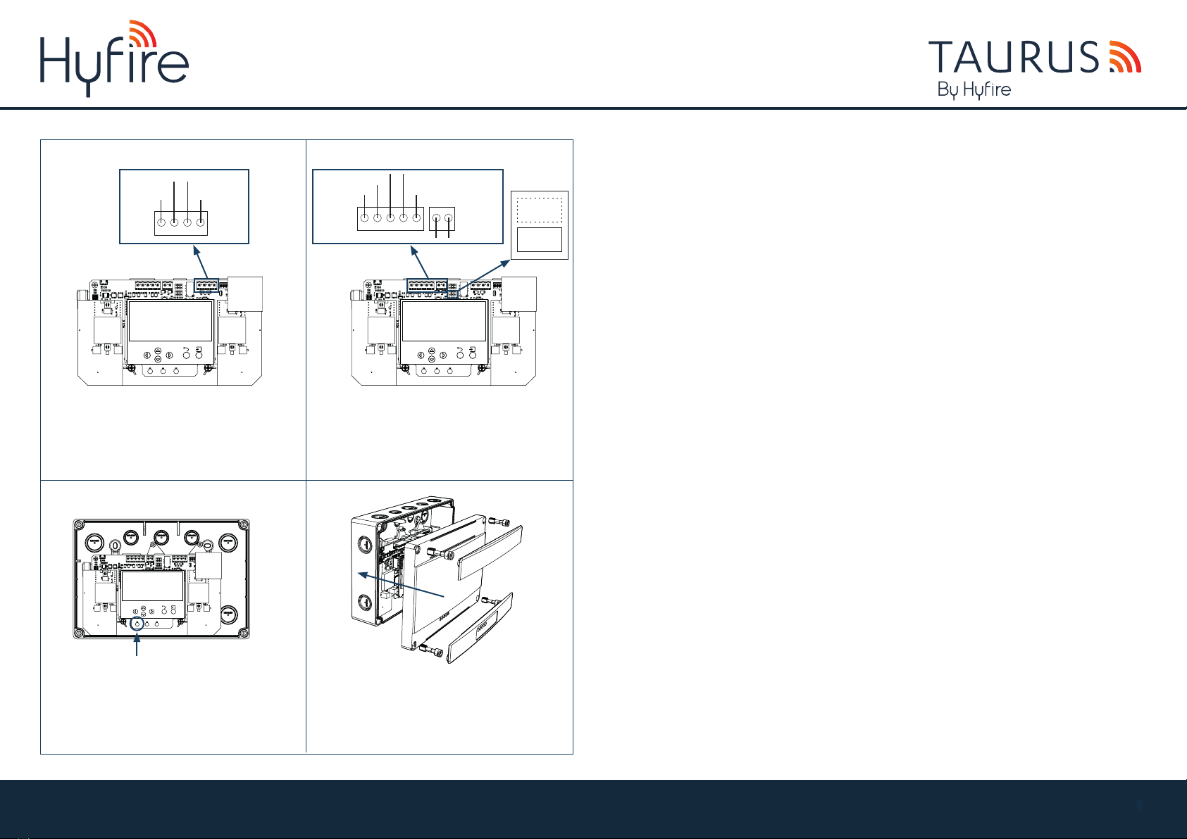
MOUNTING STEPS
The Translator Module is IP65 rated, suitable for external mounting. The back box must be installed on the wall
as flat as possible to retain IP rating, to prevent distortion of the housing and the ingress of contamination and/or moisture.
Proceed as follows to complete the device installation.
Remove top and bottom front plastics that cover screws,
unscrew all four screws and remove the lid fromthe back box.
1
3
2
4
5
Using a suitable-sized drill bit (4mm) drill the pre-defined
screw mounting points in the 4 corners of the backbox.
6
SCREWS
Remove the electronic PCB assembly from the enclosure.
The PCB is held by two Philips screws below the display,
it then slides up and out.
Prepare apertures (20mm knockouts) required for cable
access and fit appropriate rated glands.
Screw the back box to the wall using all fixing holes
and appropriate-sized roundhead screws (do not use
countersunk screws). Insert cable,tighten glands and refit PCB and securing screws.
MOUTING HOLES
SCREWS HOLES
NO
YES
INSIDE THE BOX
• 1 x Translator Module
• 4 x Screws
• 1 x Quick start guide
• 1 x QR code
TAU-TRM-01
HYFIRE TAURUS TRANSLATOR MODULE
QUICK START GUIDE
Unit B12a, Holly Farm Business Park, Honiley, Warwickshire, CV8 1NP
T
: +44 (0)1926 485282, E: info@hyfirewireless.co.uk, W: www.hyfirewireless.com
L50-MTI-1400 (Rev_P.3)
THE BOX
Taurus QR code
Manual QR code
Product code
Product name
TAU-TRM-01
Hyfire Taurus
Translator Module
UNBOXING
• The Expander has removable top and bottom front plastics to cover screw housings.
• The Expander is housed in an IP65 rated box with knockouts for IP rated glands.
• 4 plastic screws are provided to secure the lid.
For more information, please refer to the complete product manual.
IMPORTANT TO CONSIDER
When mounting a wireless device a comprehensive radio survey
should have been carried out to establish the location that provides
the best coverage and optimum reach. Taking into consideration the building
structure and materials, the survey identifies the wireless infrastructure
required and product locations for optimum performance, identifying
any factor that could prevent radio integrity.
Avoid fixing or mounting the unit close to the following:
• Equipment that utilises large electrical currents
• Large metal objects or structures
• Fluorescent lighting fittings
• Metal ceiling structures
• IT cabling.
Keep 2 meters minimum spacing between other wireless equipment
in the area to avoid signal interference.
EN54 approved environmental temperature range is -10°C to +55°C
MOUNTING STEPS
The Expander Module is IP65 rated, suitable for external mounting. The back box must be installed on the wall as flat as possible
to retain IP rating, to prevent distortion of the housing and the ingress of contamination and/or moisture.
Proceed as follows to complete the device installation.
Remove top and bottom front plastics that cover screws,
unscrew all four screws and remove the lid from the back box.
.
1
3
2
4
5
Using a suitable-sized drill bit (4mm) drill the pre-defined
screw mounting points in the 4 corners of the backbox.
6
SCREWS
Remove the electronic PCB assembly from the enclosure.
The PCB is held by two Philips screws below the display,
it then slides up and out.
Prepare apertures (20mm knockouts) required for cable
access and fit appropriate rated glands.
Screw the back box to the wall using all fixing holes
and appropriate-sized roundhead screws (do not use
countersunk screws). Insert cable, tighten glands and refit PCB and securing screws.
MOUTING HOLES
SCREWS HOLES
NO
YES
INSIDE THE BOX
• 1 x Expander Module
• 4 x Screws
• 1 x Quick start guide
• 1 x QR code
TAU-EXM-01
HYFIRE TAURUS EXPANDER MODULE
QUICK START GUIDE
Unit B12a, Holly Farm Business Park, Honiley, Warwickshire, CV8 1NP
T: +44 (0)1926 485282, E: info@hyfirewireless.co.uk, W: www.hyfirewireless.com
L50-ME-1400 (Rev_P.3)
THE BOX
Taurus QR code
Manual QR code
Product code
Product name
TAU-EXM-01
Hyfire Taurus
Expander Module
•1 x CR2032 battery
Battery not included for item
code TAU-TRM-01/NB
6
Available also without batteries: TAU-TRM-01/NB
Available also in black plastic: TAU-TRM-01-BL
Available also in black plastic without batteries: TAU-TRM-01-BL/NB