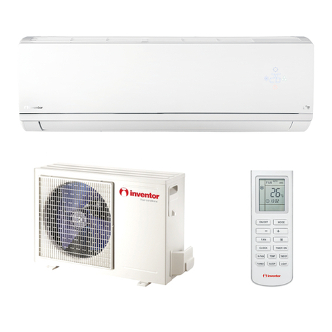
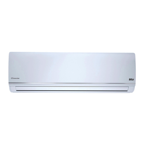
Inventor Air Conditioners IKI-09 User manual

66129903851
IKI-09
IKI-12
IKI-18
IKI-24
IKI-36
IKI-45
IKI-50
Floorceiling Unit


Safety Considerations 1
Wire controller(standard fitting) 2
Turning On/Off Unit 3
Fan Control 3
Temperature Setting 3
Swing Function Setting 4
Component
Description
Sleep Function Setting 4
Operating Mode Setting 5
Timer Setting 6
Energy Saving Setting 6
Display of Outdoor Ambient Temperature 7
Power-fail Memory Function Setting 7
Debug Function 7
Operating
Instructions
for Line
Controller
Failure Display 8
Profile Dimensions of Outdoor Unit 38
Operation of Remote Controller 9
Unit Function 18
Operating
Instructions
Wire controller (with week timer functions) 20
Part Names and their Functions 28
ecnanetniaM
Operating Guide 30
Precautions 31
Checking Before Contact The Service Man 32
Indoor Unit Installation 33
Outdoor Unit Installation 36
Schematic Diagram of Unit Line Connection 39
Position and Method of Installing Wire Controller
Connecting Pipe Prepartion 44
Drain Piping Work 48
Routine Check after Installation 49
Installation
Instructions
for Air Duct
gninnuRtseT
41
50
29


Safety Considerations
Please read this manual carefully before use and operate correctly as instructed in the manual.
1ˊYou are specially warned to note the two symbols below.:
WARNING!˖A symbol indicating that improper operation might cause human death or severe
injuries.
A symbol indicating that improper operation might cause human injury or property
damage.
z This unit shall be used in the houses, offices, restaurants, residences or similar places.
WARNING!
z Please seek an authorized repair station for installation work. Improper installation might cause water leakage,
electric shock or fire.
z Please install at a place strong enough to support the weight of air conditioner unit. If not, the air conditioner
unit might fall down and cause human injury or death.
z To ensure proper drainage, the drainage pipe shall be correctly installed according to installation instructions.
Take proper measures for heat preservation to prevent condensing. Improper installation of pipes might cause
leakage and wet the articles in the room.
z Do not use or store flammable, explosive, poisonous or other dangerous substances beside the air conditioner.
z In case of trouble (e.g. burnt smell), please immediately cut off the main power of air conditioner unit.
z Keep air flow to avoid shortage of oxygen in the room.
z Never insert your finger or any objects into air outlet and inlet grill.
z Never plug or unplug the power cable directly to start or stop the air-conditioning unit.
z Please take constant care to check if the mounting rack is damaged after long use.
z Never modify the air conditioner. Please contact the dealer or professional installation workers for repair or
relocation of the air conditioner.
z The appliance shall not be installed in the laundry.
WARNING!:
z Before installation, please check the power supply for compliance with the ratings on nameplate. Check the
power safety as well.
z Before use, please check and confirm if the cables, drainage pipes and pipelines are correctly connected,
hence to eliminate the risk of water leakage, refrigerant leakage, electric shock or fire.
z Main power must be securely earthed to ensure effective grounding of air conditioner unit and avoid the risk
of electric shock. Please do not connect the earthing cable to coal gas pipe, water pipe, lightning rod or
telephone line.
z Once started, the air conditioner shall not be stopped at least after 5 minutes or longer; otherwise the oil
return to compressor may be affected.
z Do not let the child to operate the air conditioner unit.
z Do not operate the air conditioner unit with wet hands.
z Please disconnect the main power before cleaning the air conditioner or replacing the air filter.(Operating by
professinal)
z Please disconnect the main power if to put the air conditioner unit out of use for a long period.
z Please do not expose the air conditioner unit directly under corrosive environment with water or moisture.
z Please do not foot on or place any goods on air conditioner unit.
z After electrical installation, the air conditioner unit shall be energized for electrical leakage test.
z If the supply cord is damaged, it must be replaced by the manufacturer or its service agent or a similarly
qualified person in order to avoid a hazard .
z An all-pole disconnection switch having a contact separation of at least 3mm in all poles should be connected
in fixed wiring.
z The appliance shall be installed in accordance with national wiring regulations.
z The temperature of refrigerant circuit will be high, please keep the interconnection cable away from the
copper tube.
1
zThe installation, cleaning and maintenance work must be done by a qualified person. Do not do such work by
yourself.

Wire controller (standard fitting)
•Never install the wire controller in a place where is water leakage.
• Avoid bunping, throwing, tossing or frequently opening the wire controller.
SWING
TIMER
1Timing display
2Fan speed display (Auto, High speed, Medium
speed, Low speed)
3Defros ting st atus display
4Energy savingst atus display
5Set temperature display
6Ambient temperatur e display
7Fresh air st atus display (not supplied)
8Mode (cooling, dehumidifying,fan, heating, auto)
9Failure status display
10 Sleep st atus display
11 Mode key
12 Set temperature incr ease key
13 Set temperature decr ease key
14 Fan speed key (fresh air setting)
15
Swing key (outdoor environment temperature check)
16 Timing key
17 ON/OFF key
Composition of wire controller
SWING
2

Turning ON/OFF unit
Pr ess t he ON/OFF ke y, then the unit shallstar t up. Pr ess t he ON/OFF
key again, then the unit shall shut off.
Fan contr ol (the figur es show the r elevant display ar eas)
If the fan control key is prssed consecutively, the fan speed shall changes
as per t he following sequence:
Low speed Medium speed Hight speed Auto
In the dehumidifying mode: The fan speed shall be automaticallyset as
low.
Oper ating istructions of wire controller
Temperatur e setting
Pr ess the temperature seting key ( ) to increase the set temperature;
press the temperature setting key ( ) to decrease the set temperature
(when pressing the keys once, the temperature shall increase or decrea-
se by 1 °C). NOTE: key lock function: when the ( ) and ( ) key ar epressed
simultaneously for 5 second, the set temperature indicating ar ea shall
display “EE” and all keys response shall be shut off; press the two keys
simultaneously for 5 second again, the key lock function shall be relea-
sed. When the wire controller is locked by remote monitor or centra lized
controller, the keys of the wire controller and the signal of the remote
controller ar e all locked and invalidated, and then the set temperature
indicating ar ea shall display “CC”. Range of temperature setting under
various modes:
Heating: 16 °C~30 °C Cooling: 16 °C~30 °C
Dehumidifying: 16 °C~30 °C
Fan: No temperature se tting function
3
SWING
SWING
SWING
TIMER
TIMER
TIMER

Sleep function setting
SWING
TIMER
When under the cooling or dehumidifying mode, after receiving the
SLEEP order for 1 hour, the previous set temp. Tset will be risen for
1ć, and another 1ćwill be risen after 2 hours that means that the
temperature been risen 2ćwithin 2 hours. Then the unit will run
according to this set temp.
When under the heating mode, after receiving the SLEEP order for 1
hour, the previous set temp. Tset will be lower for 1ć, and another 1
ćwill be lower after 2 hours that means that the temperature been
lowered 2ćwithin 2 hours. Then the unit will run according to this
set temp.
There is no SLEEP mode under fan mode.
Note˖The wired remote controller has no SLEEP mode button; if
SLEEP mode is needed to be set, complete the procedure by
wireless remote controller.
SWING
SWING
Swing function setting
Press Swing button then the swing mode will be operated by the
air conditioner.
Repress Swing button once to stop swing mode.
Note: There is no swing mode for duct type indoor unit
4
TIMER

/PERATING-ODE3ETTING
THIS KEY ISPRESSED CONSECUTIVELYTHEOPERATING MODESHALLCHANGEAS
PERTHEFOLLOWINGSEQUENCE
#OOLING$EHUMIDIFYING&AN(EATING!UTO
7HENTHEUNITOPERATESUNDERh#OOLINGvMODEh#//,vSHALLBEDISPLAYED
.OWTHESETTEMPERATUREMUSTBELOWERTHANTHEAMBIENTTEMPERATURE
.OWIFTHESETTEMPERATUREISHIGHERTHANTHEAMBIENTTEMPERATURETHE
UNIT SHALL NOT PRODUCE COOLING EFFECT BUT SHALL ONLY OPERATE UNDER &AN
MODE
7HEN THE UNIT OPERATES UNDER h$EHUMIDIFYINGv MODE h$29v SHALL BE
DISPLAYED.OWTHEINTERIORFANSHALLOPERATEINTHEMANNEROFLOWSPEED
AIR SUPPLY WITHIN A CERTAIN RANGE OF TEMPERATURES 4HE DEHUMIDIFYING
EFFECT OF THIS MODE IS BETTER THAN THAT OF THE #OOLING MODE AND SAVES
MOREENERGY
7HENTHEUNITOPERATESUNDERh(EATINGvMODEh(%!4vSHALLBEDISPLAYED
.OWTHESETTEMPERATUREMUSTBEHIGHERTHANTHEAMBIENTTEMPERATURE
.OWIFTHESETTEMPERATUREISLOWERTHANTHEAMBIENTTEMPERATURETHE
HEATINGFUNCTIONSHALLNOTBESTARTED
7HEN THE UNIT OPERATES UNDER h&ANv MODE h&!.v SHALL BE DISPLAYED
7HEN THE UNIT OPERATES UNDER h!UTOv MODE h!54/v SHALL BE DISPLAYED
ANDTHE UNIT SHALL ADJUST ITSOPERATING MODE AUTOMATICALLY ACCORDING TO
THEAMBIENTTEMPERATURE
7HENTHEUNITOPERATESUNDER(EATINGMODEANDTHEOUTDOORTEMPERA
TURE IS LOW AND THE HUMIDITY IS HIGH FROST SHALL PRODUCE AT THE OUTDOOR
UNIT.OWTHE HEATINGEFFICIENCYSHALLBEDECREASED7HENFROSTINGHAP
PENSTHECONTROLLERSHALLAUTOMATICALLYSTARTTODEFROSTANDh$%&2/34v
SHALLBEDISPLAYED
.OTE#OOLINGONLYTYPEUNITDOESNOTHAVEHEATINGMODEANDWHENENER
GYSAVINGISSETTHE!UTOMODESHALLBEINVALIDATED
SWING
TIMER
5

%NERGY3AVING3ETTING
7HENTHEUNITISSHUTOFFPRESSTHEh&!.vKEYANDTHESIMULTANEOUSLYFOR
CONSECUTIVESECONDSTOACTIVATETHEENERGYSAVINGSETTINGMENU.OWh3!6%v
ANDh#//,vAREDISPLAYED)NCASEITISTHEFIRSTTIMETOSETENERGYSAVINGTHEINI
TIALVAL ESHALLBEDISPLAYED4HELOWERLIMITOFTEMPERATURESHALLBEDISPLAYED
ONTHESETTEMPERATUREANDTHETEMPERATUREVALUEUNDERSETTINGSHALLFLASH3ET
THELOWERLIMITOFCOOLINGTEMPERATUREUSINGTHEKEYORTHEKEYTHELOWER
LIMIT TEMPERATURE CAN BE SELECTED FROM THE RANGE BETWEEN 0RESS THE
h/./&&vKEYTOCONFIRMTHESETTING!LSOUSETHEKEYORTHEKEYTOSETTHE
UPPERLIMITOFTEMPERATUREANDTHETEMPERATUREVALUESHALLFLASHONTHEAMBIENT
TEMPERATUREAREA/54%.6AREATHEUPPERLIMITTEMPERATURECANBESELECTED
FROMTHERANGEBETWEEN0RESSTHEh/./&&vKEYTOCONFIRMTHESETTING
0LEASEPAY ATTENTIONTHATTHEUPPERLIMIT TEMPERATURE MUSTBE HIGHERTHAN THE
SETLOWERLIMITTEMPERATURE/THERWISETHESYSTEMSHALLREGARDTHEHIGHERTEM
PERATURE AS THE UPPER LIMIT TEMPERATURE AND THE LOWER ONE AS THE LOWER LIMIT
TEMPERATURE 0RESS THE h-/$%v KEY TO COMPLETE THE ENERGY SAVING SETTING FOR
THEMODESOFCOOLINGANDDEHUMIDIFYINGANDTURNTOTHEENERGYSAVINGSETTINGFOR
THE HEATING MODE #OOLING ONLY UNIT DOES NOT HAVE THIS FUNCTION .OW THE ,#$
DISPLAYSh3!6%vANDh(%!4v!FTERSETTINGISCOMPLETEDPRESSTHEh&!.vKEY
ANDTHEKEYSIMULTANEOUSLYFORCONSECUTIVESECONDSTOEXITTHESETTINGOF
ENERGYSAVING!FTERTHEENERGYSAVINGSETTINGINTERFACEISACTIVATEDTHESYSTEM
SHALLEXITTHEINTERFACEIFTHEREISNOANYOPERATIONWITHIN20 seconds afTERTHE
LASTKEYINPUTANDTHENORMALSHUTOFFSTATUSINTERFACESHALLBEDISPLAYED!FTER
THEABOVESETTINGSARECOMPLETEDTHESYSTEMSHALLDISPLAYh3!6%v.OWTHESET
TEMPERATURESHALLNOTEXCEEDTHETEMPERATURERANGEOFTHEENERGYSAVINGSET
TINGBEFORE&OR EXAMPLE THE LOWERCOOLING LIMITISSET AS ²#ANDTHE UPPER
COOLINGLIMITISSETAS²#FORTHEENERGYSAVINGTEMPERATURESETTINGIN
SOTHECOOLINGTEMPERATURECANONLYBESELECTEDFROMTHERANGEOF²#TO²#
BYUSINGTHEREMOTECONTROLLERORTHEWIRECONTROLLERLATER)FTHEUPPERLIMITTEM
PERATUREISTHESAMEASTHELOWERLIMITTEMPERATURETHESYSTEMCANONLYOPERA
TEATSUCHTEMPERATUREUNDERRELEVANTMODES2EMOVEOFENERGYSAVINGSETTING
4OREMOVETHEENERGYSAVINGSETTINGAFTERITTAKESINTOEFFECTYOUCANPRESSTHE
h&!.vANDTHEKEYSIMULTANEOUSLYFORCONSECUTIVESECONDSWHENTHEUNITIS
SHUTOFF"UTTHEVALUESETBEFOREWILLNOTBECLEAREDBUTASTHEINITIALSETTEMPE
RATUREFORTHENEXTENERGYSAVINGSETTING!FTERTHEUNITISDISCONNECTEDTOPOWER
SUPPLYTHEENERGYSAVINGSETTINGSHALLBESTORED4HESETTINGSTILLFUNCTIONSWHEN
THEUNITISCONNECTEDTOPOWERSUPPLYAGAIN)FTHEENERGYSAVINGMODEISSETTHE
SLEEPMODEANDTHEAUTOMODESHALLBEINVALIDATED
Timer Setting
When the unit is shut off, timing start can be set; After the unit is
started up, timing shutoff can be set. After the "TIMER"key is pressed,
the unit enters the timing set status and the word "TIMER" flashes on
the display. Now user can press ( ) or ( ) key to increase or decrease
the set time. Press the "TIMER" key again and then the timing shall
go into effect. Now the unit starts to count the time passed. When the
unit is under timing status, you can cannel timing set by pressing the
“TIMER” key.The range of set time is between 0.5 to 24 hours.
6
left.
U
TIMER
TIMER
SWING
SWING
$ISPLAYOF/UTDOOR!MBIENT4EMPERATURE
5NDERNORMALCONDITIONSTHEh/54%.6vCOLUMNSHALLONLYDISPLAYTHE
INDOORTEMPERATURE0RESSTHEh3,%%0vKEYFORCONSECUTIVESECONDS
WHENTHEUNITISSHUTOFFORSTARTUPTHE,#$SHALLDISPLAYh/54%.6v
!FTERTHEOUTDOORTEMPERATUREISDISPLAYEDFORSECONDSTHESYSTEM
SHALLRETURNTOTHEDISPLAYINTERFACEOFINDOORTEMPERATURE.OTE)FNOT
EQUIPPEDWITHANOUTDOORAMBIENTSENSORTHEUNITSHALLNOTHAVETHIS
FUNCTION
0OWERFAIL-EMORY&UNCTION3ETTING
0RESSANDHOLDTHEh-/$%vKEYFORSECONDSWHENTHEUNITISSHUTOFF
TOSWITCHSETVALUESSOASTODECIDEIFTHEUNITOPERATINGSTATUSORSHUTOFF
STATUSSHALLBEMEMORIZEDAFTERAPOWERFAIL)FTHESETTEMPERATUREAREA
DISPLAYSITMEANSTHEUNITOPERATINGSTATUSORSHUTOFFSTATUSSHALLBE
MEMORIZEDAFTERAPOWERFAILMEANSTHEOPERATINGSTATUSORSHUTOFF
STATUSSHALLNOTBEMEMORIZED0RESSTHEh/./&&vKEYTOSTORETHESET
VALUEANDEXITTHESETTING
7
TIMER
TIMER
SWING
SWING
Debug Function Setting
When the unit is shut off, press the “FAN” key and the “SWING” key
Simultaneously to activate the debug menu. Now the LCD displays
“DEBUG”. Press the “MODE” key to select setting item and use
the( ) key or the ( ) key to set actual value.
Setting of Ambient Temp. Sensor
Under the debug mode , press the “MODE” key so as to display “01”
On the set temperature area (at the left of “DEBUG”). The OUT ENV
area (at the right of “DEBUG”) displays setting status. Now use the
( ) key or the ( ) key to select from the following two settings:
The indoor room temperature is measured at the air intake(Now the
OUT ENV area displays 01).
The indoor room temperature is measured at the wire controller (Now
the OUT ENV area displays 02).
The indoor room temperature is measured at the wire controller when
the mode is 'heating' or 'auto'. At other modes, it is measured at the
air intake (Now the OUT ENV area displays 03) ,The default is 03.
R
SWING
12

8
Failure Display
When there is failure in the unit operation, “ERROR”
will flash on the LCD of the wire controller and the code
of failure will also be displayed. When there are
multiple failures at the same time, the codes of failures
will be displayed one after one on the wire controller.
The first digit of the code denotes the system number.
When there is only one system, it will display the syst-
em number 1. The last two digits denote the detailed
failure code. For example, the code in left means low
pressure protection of compressor.
The Codes of Failure Definitions are as Follows:
Fault code Fault Fault code Fault
E0 Pump Failure F0 Failure of Indoor Room Sensor at Air
Intake
E1 Compressor High Pressure
Protection
F1 Failure of Evaporator Temp. Sensor
E2 Indoor Frost-Proof Protection F2 Failure of Condenser Temp. Sensor
E3 Compressor Low Pressure
Protection
F3 Failure of Outdoor Ambient Sensor
E4 Compressor Exhaust High
Temperature Protection
F4 Failure of Exhaust Temp. Sensor
E5 Compressor Overheat F5 Failure of Indoor Room Sensor at Wire
Controller
E6 Communications Failure
E8 Indoor Fan Protection
E9 Full Water Protection
E5 Material Malfunction Will Be Showed By The Indicator Light On The Mother Board Of Outside Unit
SWING
R

/PERATIONOF2EMOTE#ONTROLLER
Name and F unction-R emote Control
SWING button
When it is pressed, the louvers
start to rotate automatically and
stop when repressed.
T E M P . button
TEMP. increases1 by pressing
button once,and decreases 1
by pressing button once.
At COOL mode operation, SET
TEMP. canbeselectedfrom16 to
30 .
A t D R Y mode operation, SE T T E M P.
can be sel ected from 16 to 30 .
At HEAT mode operation, SET
TEMP. canbeselectedfrom16 to
30 .
M O D E button
Press thi s button to change the
operation mode in order of
FAN button
Press this button to change
the fan speed of:
COOL mode
DRY mode
FAN mode
HEAT mode
ON/OFF button
Pressthisbuttontoturnon
or turn off the unit.
ON/OFF
AUTO
Note:
Besurethat ther e areno obstructions.
Don’t drop or throw theremote controller.
Don’ t place the r emote contr oller in a location exposed to dir ect sunlight.
9

Liquid crystal displayer It
shows all set contents.
SLEEP button
Press this button to set
SLEEP operation.
TIMER OFF button
A t operating, press T I M E R
OFF button, set OFF TIME
in range of 0 to 24 hour to
stop the unit automatically.
T I M E R O N button
A t stopping, press T I M E R
ON button, set ON T I M E i n
range of 0 to 24 hour to start
the unit automatically.
ON/OFF
Remote control operation procedure
Name and F unction-R emote Control. (Remove the cover)
Note: This type of remote controller is a kind of new current controller. Some buttons of
the controller which are not available to this air conditioner will not be described
below.
0

C O O L mode oper ation pr ocedur e
4.Press FA N button, set
fan speed.
5.Press T E M P. but-
ton, set suitable
TEMP.
2.Press M ODE button,
set operation
mode.
3.Press SW I NG button,
the louvers start to ro-
tate automati cal l y, and
stop when repress.
1.Plug in, press ON/OFF button,then
air conditioner is turned on.
ON/OFF
Remote control operation procedure
According to differ ence between room temp. and set temp., microcomputer can control cooling
on or not.
If room temp. is higher than set temp., compressor runs at COOL mode.
I f room temp. is lower than set temp., compressor stops and only indoor fan motor r uns.
Set T E MP. should be in range of 16 to 30
1

HEAT modeoperation pr ocedur e
I f r oom temp. is lower than set temp., compressor r uns at H EAT mode;
I f room temp. is higher than set temp., compressor and outdoor fan motor stop, only indoor fan
motor runs.
Set T E MP. should be in range of 16 to 30
4.Press FA N button, set
fan speed.
5.Press T E M P. but-
ton, set suitable
TEMP.
1.Plug in, press ON/OFF button,then
air conditioner is turned on.
2.Press M ODE button,
set operation
mode.
3. Press S W I N G button, the
louvers start to rotate
automatically, and stop
when repress it.
ON/OFF
Remote control operation procedure
2

ON/OFF
DR Y mode oper ation pr ocedur e
3.Press SW I NG button,
the louvers start to ro-
tate automati cal l y, and
stop when repress it.
4.Press T E M P.button,set
suitable T E M P.
2.Press M ODE button,set
operation mode.
1.Plug in,press
ON/OFF
button,
then air conditioner is turned on.
Remote control operation procedure
3
If room Temp.is more than 2 below Set TEMP., compressor and outdoor unit fan motor
stop,indoor unit fan motor runsas low speed.
If room Temp. is more than 2 above Set TEMP., compressor and outdoor unit fan motor
run as COOL mode , indoor unit fan motor runsatlow speed.
If room Temp. is between 2 of Set TEMP.,the compressor and outdoor unit fan motor will
run for 6 minutes and stop for 4 minutes, and always in such a cycle, the indoor unit fan motor
will run at low speed.
Set TEMP. should be in range of 16 to 30 .
℃℃
℃
℃
℃
±

ON/OFF
AUTO modeoperation pr ocedure
At AUTO mode operation, standardTEMP. is25 for C OOL mode and 20 for HEAT
mode.
2.A ccording to room temp.,micro-
computer can automatically set
operation
mode,so as for best effect.
1.Plug in,Press
ON/OFF
button, then
air conditioner is turned on.
Remote control operation pr ocedure
4

ON/OFF
TIMER operation procedure
A t stopping,press T I ME R
ON button, set O N T I M E
in range of 0 to 24 hour to
start the unit automatically.
A t operati ng,press T I M E R
O F F button.set O F F T I M E
in range of 0 to 24 hour to
stop the unit automatically.
Remote control operation procedure
5

ON/OFF
SLEEP modeoperation procedur e
4.Press FA N button, set
fan speed.
5.Press T E M P. but-
ton, set suitable
TEMP.
1.Plug in, press ON/
OFF
button,then
air conditioner is turned on.
2.Press M ODE button,
set or op-
eration mode.
3.Press SW I NG button,
the louvers start to rotate
automatically, and stop
when repress.
6.SLEEP button
Press it to set SL EEP
operation.
W hen the unit is cooling or drying, if SL E E P operation is set, T E MP. would increase 1 in 1
hour and 2 in 2 hours. Indoor fan motor r uns at low speed.
W hen the unit is heating , if SL E E P operation is set, T E MP. would decrease 1 in 1 hour and
2in 2 hour s. I ndoor fan motor runs at low speed.
Remote control operation procedure
R emote contr ocedure
16
This manual suits for next models
6
Table of contents
Other Inventor Air Conditioners Air Conditioner manuals

Inventor Air Conditioners
Inventor Air Conditioners GG52Eng User manual

Inventor Air Conditioners
Inventor Air Conditioners L2VI-09 User manual

Inventor Air Conditioners
Inventor Air Conditioners WGN18D/GN18D User manual

Inventor Air Conditioners
Inventor Air Conditioners L4VI32-18 User manual

Inventor Air Conditioners
Inventor Air Conditioners L3VI-09 User manual