Inventor Air Conditioners WGN18D/GN18D User manual

Service Manual
WGN18D/GN18D
WGN24D/GN24D
R32

Service Manual
Table of Contents
Part Ⅰ: Technical Information.......................................................................1
1. Summary......................................................................................................................1
2. Specications..........................................................................................................3
2.1 Specication Sheet...........................................................................................................3
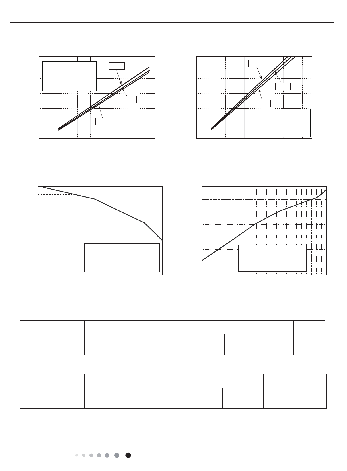
2.2 Operation Characteristic Curve ......................................................................................11
2.2 Capacity Curve in Different Outdoor Temperature .........................................................11
2.3 Cooling and Heating Data Sheet in Rated Frequency ................................................... 11
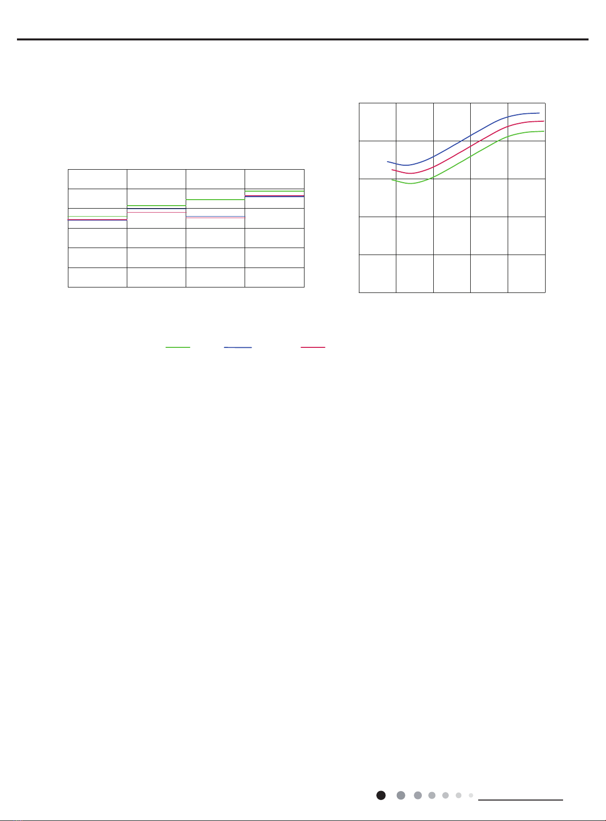
2.5 Noise Curve....................................................................................................................12
3. Outline Dimension Diagram......................................................................13
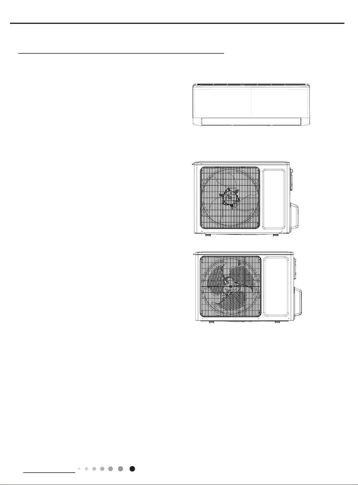
3.1 Indoor Unit......................................................................................................................13
3.2 Outdoor Unit ...................................................................................................................14
4. Refrigerant System Diagram....................................................................16
5. Electrical Part.........................................................................................................17
5.1 Wiring Diagram...............................................................................................................17
5.2 PCB Printed Diagram .....................................................................................................20
6. Function and Control......................................................................................23
6.1 Remote Controller Introduction .....................................................................................23
6.2 GREE+ App Operation Manual ......................................................................................27
6.3 Ewpe Smart App Operation Manual...............................................................................28
6.4 Brief Description of Modes and Functions......................................................................29
Part Ⅱ: Installation and Maintenance .................................................38
7. Notes for Installation and Maintenance..........................................38
8. Installation................................................................................................................42
8.1 Installation Dimension Diagram......................................................................................42
8.2 Installation Parts-checking ............................................................................................44
8.3 Selection of Installation Location....................................................................................44
8.4 Electric Connection Requirement...................................................................................44
8.5 Installation of Indoor Unit................................................................................................44
8.6 Installation of Outdoor unit .............................................................................................47
8.7 Vacuum Pumping and Leak Detection ...........................................................................48
8.8 Check after Installation and Test operation ....................................................................48
Table of Contents

Service Manual
9. Maintenance............................................................................................................49
9.1 Malfunction Display of Indoor Unit..................................................................................49
9.2 Procedure of Troubleshooting ........................................................................................51
9.3 Maintenance method for normal malfunction .................................................................69
10. Exploded View and Parts List ..............................................................71
10.1 Indoor Unit....................................................................................................................71
10.2 Outdoor Unit .................................................................................................................79
11. Removal Procedure.......................................................................................87
11.1 Removal Procedure of Indoor Unit ...............................................................................87
11.2 Removal Procedure of Outdoor Unit ............................................................................92
Appendix:......................................................................................................................112
Appendix 1: Reference Sheet of Celsius and Fahrenheit .................................................. 112
Appendix 2: Conguration of Connection Pipe................................................................... 112
Appendix 3: Pipe Expanding Method ................................................................................. 113
Appendix 4: List of Resistance for Temperature Sensor .................................................... 114
Table of Contents

1
Technical Information
Service Manual
1. Summary
Indoor Unit:
WGN18D
WGN24D
Part Ⅰ: Technical Information
Outdoor Unit:
GN24D
GN18D

3
Technical Information
Service Manual
2. Specications
2.1 Specication Sheet
Model WGN18D/GN18D
Power
Supply
Rated Voltage V~ 220-240
Rated Frequency Hz 50
Phases 1
Power Supply Mode Outdoor
Cooling Capacity W 5130
Heating Capacity W 5280
Cooling Power Input W 1600
Heating Power Input W 1450
Cooling Power Current A 7.0
Heating Power Current A 6.3
Rated Input W 2300
Rated Current A 10.8
Rated Heating Current A 12
Air Flow Volume(SH/H/M/L/SL) m3/h 850/720/610/520/-
Dehumidifying Volume L/h 1.8
EER W/W 3.21
COP W/W 3.64
SEER W/W 6.1
HSPF W/W /
Application Area m223-34
Indoor Unit
Model of Indoor Unit WGN18D
Fan Type Cross-ow
Diameter Length(DXL) mm Φ106X706
Fan Motor Cooling Speed(SH/H/M/L/SL) r/min 1230/1130/1030/800/-
Fan Motor Heating Speed(SH/H/M/L/SL) r/min 1350/1200/1050/900/-
Output of Fan Motor W 35
Fan Motor RLA A 0.35
Fan Motor Capacitor μF 2.5
Input of Heater W/
Evaporator Form Aluminum Fin-copper Tube
Pipe Diameter mm Ф7
Row-n Gap mm 2-1.4
Coil Length (LXDXW) mm 715X25.4X304.8
Swing Motor Model MP35CP
Output of Swing Motor W 2.5
Fuse A 3.15
Sound Pressure Level (SH/H/M/L/SL) dB (A) 48/44/39/34/-
Sound Power Level (SH/H/M/L/SL) dB (A) 58/54/49/44/-
Dimension (WXHXD) mm 970X300X225
Dimension of Carton Box (LXWXH) mm 1017X366X285
Dimension of Package (LXWXH) mm 1020X369X295
Net Weight kg 13.5
Gross Weight kg 16.5

4Technical Information
Service Manual
The above data is subject to change without notice; please refer to the nameplate of the unit.
Outdoor Unit
Model of Outdoor Unit GN18D
Compressor Manufacturer/Trademark ZHUHAI LANDA COMPRESSOR CO.,LTD
Compressor Model QXF-B141ZF030A
Compressor Oil 68DA
Compressor Type Rotary
L.R.A. A 25
Compressor RLA A 6.5
Compressor Power Input W 1410
Overload Protector 1NT11L-6233/KSD115oC/HPC 115/95
Throttling Method Electron expansion valve
Operation Temp oC16~30
Ambient Temp (Cooling) oC -15~43
Ambient Temp (Heating) oC -15~24
Condenser Form Aluminum Fin-copper Tube
Pipe Diameter mm Φ7.94
Rows-n Gap mm 2-1.4
Coil Length (LXDXW) mm 742X38.1X550
Fan Motor Speed rpm 780
Output of Fan Motor W 40
Fan Motor RLA A 0.62
Fan Motor Capacitor μF /
Air Flow Volume of Outdoor Unit m3/h 2400
Fan Type Axial-ow
Fan Diameter mm Φ445
Defrosting Method /
Climate Type T1
Isolation I
Moisture Protection IPX4
Permissible Excessive Operating
Pressure for the Discharge Side MPa 4.3
Permissible Excessive Operating
Pressure for the Suction Side MPa 2.5
Sound Pressure Level (H/M/L) dB (A) 56/-/-
Sound Power Level (H/M/L) dB (A) 66/-/-
Dimension (WXHXD) mm 899X596X378
Dimension of Carton Box (LXWXH) mm 945X417X630
Dimension of Package (LXWXH) mm 948X420X645
Net Weight kg 39
Gross Weight kg 42
Refrigerant R32
Refrigerant Charge kg 0.9
Connection
Pipe
Length m 5
Gas Additional Charge g/m 16
Outer Diameter Liquid Pipe mm Φ6
Outer Diameter Gas Pipe mm Φ12
Max Distance Height m 10
Max Distance Length m 25
Note: The connection pipe applies metric diameter.

5
Technical Information
Service Manual
Model WGN24D/GN24D
Power
Supply
Rated Voltage V~ 220-240
Rated Frequency Hz 50
Phases 1
Power Supply Mode Outdoor
Cooling Capacity W 6155
Heating Capacity W 6448
Cooling Power Input W 1760
Heating Power Input W 1860
Cooling Power Current A 7.7
Heating Power Current A 8.1
Rated Input W 2600
Rated Current A 10.9
Rated Heating Current A 11.3
Air Flow Volume(SH/H/M/L/SL) m3/h 850/720/610/520/-
Dehumidifying Volume L/h 1.8
EER W/W 3.5
COP W/W 3.47
SEER W/W 6.1
HSPF W/W /
Application Area m223-24
Indoor Unit
Model of Indoor Unit WGN24D
Fan Type Cross-ow
Diameter Length(DXL) mm Φ106X706
Fan Motor Cooling Speed(SH/H/M/L/SL) r/min 1230/1130/1030/800/-
Fan Motor Heating Speed(SH/H/M/L/SL) r/min 1350/1200/1050/900/-
Output of Fan Motor W 35
Fan Motor RLA A 0.35
Fan Motor Capacitor μF 2.5
Input of Heater W/
Evaporator Form Aluminum Fin-copper Tube
Pipe Diameter mm Ф7
Row-n Gap mm 2-1.4
Coil Length (LXDXW) mm 715X25.4X304.8
Swing Motor Model MP35CP
Output of Swing Motor W 2.5
Fuse A 3.15
Sound Pressure Level (SH/H/M/L/SL) dB (A) 48/44/40/34/-
Sound Power Level (SH/H/M/L/SL) dB (A) 58/54/50/44/-
Dimension (WXHXD) mm 970X300X225
Dimension of Carton Box (LXWXH) mm 1017X366X285
Dimension of Package (LXWXH) mm 1020X369X295
Net Weight kg 13.5
Gross Weight kg 16.5

6Technical Information
Service Manual
The above data is subject to change without notice; please refer to the nameplate of the unit.
Outdoor Unit
Model of Outdoor Unit GN24D
Compressor Manufacturer/Trademark ZHUHAI LANDA COMPRESSOR CO.,LTD
Compressor Model QXF-B141ZF030A
Compressor Oil 68DA
Compressor Type Rotary
L.R.A. A 25
Compressor RLA A 6.5
Compressor Power Input W 1410
Overload Protector 1NT11L-6233/KSD115oC/HPC 115/95
Throttling Method Electron expansion valve
Operation Temp oC16~30
Ambient Temp (Cooling) oC -15~43
Ambient Temp (Heating) oC -15~24
Condenser Form Aluminum Fin-copper Tube
Pipe Diameter mm Φ7
Rows-n Gap mm 2-1.4
Coil Length (LXDXW) mm 935X38.1X660
Fan Motor Speed rpm 780
Output of Fan Motor W 60
Fan Motor RLA A 0.49
Fan Motor Capacitor μF /
Air Flow Volume of Outdoor Unit m3/h 3200
Fan Type Axial-ow
Fan Diameter mm Φ520
Defrosting Method /
Climate Type T1
Isolation I
Moisture Protection IPX4
Permissible Excessive Operating
Pressure for the Discharge Side MPa 4.3
Permissible Excessive Operating
Pressure for the Suction Side MPa 2.5
Sound Pressure Level (H/M/L) dB (A) 57/-/-
Sound Power Level (H/M/L) dB (A) 67/-/-
Dimension (WXHXD) mm 955X700X396
Dimension of Carton Box (LXWXH) mm 1026X455X735
Dimension of Package (LXWXH) mm 1029X458X750
Net Weight kg 49
Gross Weight kg 50.5
Refrigerant R32
Refrigerant Charge kg 1.3
Connection
Pipe
Length m 5
Gas Additional Charge g/m 40
Outer Diameter Liquid Pipe mm Φ6
Outer Diameter Gas Pipe mm Φ16
Max Distance Height m 10
Max Distance Length m 25
Note: The connection pipe applies metric diameter.

11
Technical Information
Service Manual
2.2 Capacity Curve in Different Outdoor Temperature
2.3 Cooling and Heating Data Sheet in Rated Frequency
Heating
Rated heatling condition(°C)
(DB/WB) Model
Pressure of gas pipe connecting
indoor and outdoor unit
Inlet and outlet pipe temperature
of heat exchanger Fan speed of
indoor unit
Fan speed of
outdoor unit
Indoor Outdoor P (MPa) T1 (°C) T2 (°C)
20/- 7/6 18/24K 3.5~3.8 in:75~85
out:37~43
in:1~3
out:2~5 Super High High
Rated cooling condition(°C)
(DB/WB) Model
Pressure of gas pipe connecting
indoor and outdoor unit
Inlet and outlet pipe temperature
of heat exchanger Fan speed of
indoor unit
Fan speed of
outdoor unit
Indoor Outdoor P (MPa) T1 (°C) T2 (°C)
27/19 35/24 18/24K 0.8~1.0 in:8~11
out:11~14
in:75~85
out:37~43 Super High High
Cooling
Instruction:
T1: Inlet and outlet pipe temperature of evaporator
T2: Inlet and outlet pipe temperature of condenser
P: Pressure at the side of big valve
Connection pipe length: 5m.
Cooling Heating
32 33 34 35 36 37 38 39 43 –15 –10 –5
40 41 42
100
105
95
90
85
80
75
70
65
60
55
50
110
100
90
80
70
60
50
40
05
710
Conditions
Indoor:DB27°C/WB19°C
Indoor air flow:Super High
Pipe length: 5m
Conditions
Indoor:DB20°C/WB15°C
Indoor air flow:Super High
Pipe length: 5m
Outdoor temp.(°C) Outdoor temp.(°C)
Capacity ratio (%)
Capacity ratio (%)
Cooling Heating
2.2 Operation Characteristic Curve
01020304050607090010 20 30 40 50 60 70 80 90 100 120110
80
11
10
9
8
7
6
5
4
3
2
1
0
Compressor speed (rps)
)A(tnerruC
11
10
9
8
7
6
5
4
3
2
1
0
Compressor speed (rps)
)A(tnerruC
220V
230V
240V
220V
230V
240V
01020304050607090010 20 30 40 50 60 70 80 90 100
120
110
80
11
10
9
8
7
6
5
4
3
2
1
0
Compressor speed (rps)
)A(tnerruC
11
10
9
8
7
6
5
4
3
2
1
0
Compressor speed (rps)
)A(tnerruC
220V
230V
240V
220V
230V
240V
Conditions
Indoor: DB27°C/WB19°C
Outdoor: DB35°C/WB24°C
Indoor air flow: High
Pipe length: 5m
Conditions
Indoor: DB27°C/WB19°C
Outdoor: DB35°C/WB24°C
Indoor air flow: High
Pipe length: 5m
Conditions
Indoor: DB20°C/WB15°C
Outdoor: DB7°C/WB6°C
Indoor air flow: High
Pipe length: 5m
Conditions
Indoor: DB20°C/WB15°C
Outdoor: DB7°C/WB6°C
Indoor air flow: High
Pipe length: 5m
Cooling Heating

12 Technical Information
Service Manual
2.5 Noise Curve
Indoor side noise
60
50
40
30
20
10
0
Indoor Fan Motor Rotating Speed
Noice/dB(A)
low Middle High Super High
Outdoor side noise
Compressor frequency/Hz
Noise/dB(A)
70
60
50
40
30
02040608
01
00
20
24K
18K 18K

13
Technical Information
Service Manual
104 685 181
140
190
38
Φ55 Φ55
38
133 542 174
43
43
80
143
Ф55Ф55
104 685 181
140
190
38
Φ55 Φ55
38
133 542 174
43
43
80
143
Ф55Ф55
3. Outline Dimension Diagram
3.1 Indoor Unit
Unit:mm
W
H
D
Model WH D
18/24K 970 300 225

14 Technical Information
Service Manual
899
818
596
378
303
343
550
Unit:mm
Unit:mm
897
560
955 340
396
364
700
3.2 Outdoor Unit
GN18D
GN24D

16 Technical Information
Service Manual
4.
Cooling and heating model
Indoor unit Outdoor unit
COOLING
HEATING
4-Way valve
Discharge
Suction
Heat
exchanger
(evaporator)
Heat
exchanger
(condenser)
Valve
Valve
Liquid pipe
side
Gas pipe
side
Strainer Electric
expand
valve
Strainer
Compressor
Accumlator
Refrigerant System Diagram
GN18D
GN24D

17
Technical Information
Service Manual
Symbol Symbol Color Symbol Symbol Color Symbol Name
WH White GN Green CAP Jumper cap
YE Yellow BN Brown COMP Compressor
RD Red BU Blue Grounding wire
YEGN Yellow/Green BK Black / /
VT Violet OG Orange / /
5. Electrical Part
5.1 Wiring Diagram
● Indoor Unit
●Instruction
Note: Jumper cap is used to determine fan speed and the swing angle of horizontal lover for this model.
60000700068802
76(1625
7(03
6(1625
7(03
6(1625
57
522078%(
67(33,1*
',63/$<
35,17('&,5&8,7%2$5'
5(&(,9(5$1'
',63/$<%2$5'
&$%/(
&211(&7,1*
6:,1*8'
02725
%/2&.
7(50,1$/
$3
-803
&$3 %8
%.
<(*1
(9$325$725
3(
;7
1
0
287'22581,7
$3
3*
*(1(5$725
&2/'3/$60$
)$102725
0 5' %8
+($/7+1
+($/7+/
3*)
',63 ',63
%1
<(*1
57
1
&20287
$&/
%8
%.
%1
/
/
:,),
02'8/(
:,),
$3
0$*1(7,&
5,1*
WGN18D, WGN24D

19
Technical Information
Service Manual
● Outdoor Unit
63610000218
$&B/
1
&20B,11(5
:$51,1*
3OHDVHGRQWWRXFKDQ\
WHUPLQDOZKHQWKHYROWDJH
RIWHUPLQDO3'&DQG
1'&DW$3LVKLJKHU
WKDQ9WRSUHYHQWWKH
ULVNRIHOHFWULFVKRFN
$3
7(036(1625
(;+$867
7(036(1625
2875220
28778%(
7(036(1625
%.:+
%8 <(
;
&203
6$7
:+ :+
29&B&203
5'
575757 3(
3(
5'%8 <(
8%8 9<( :5'
<(*1
29(5/2$'3527(&725
/
0$*1(7,&
5,1* //
3(
<(*1
3( 9DOYH
([SDQVLRQ
(OHFWURQLF
(.9
3(
0
:$<
<9
9$/9(
97 97
)$ 2)$1:$<
)$102725
<(*1
3(
35,17('&,5&8,7%2$5'
8
9:
/
&203
7B6(1625
%1%.
32:(5
/
/
0$*1(7,&
3(
7(50,1$/
%/2&.
<(*1
%8
%1
%8
%1
%.
5,1*
/
,1'22581,7
;7
%8
%.
%1
1
/
1
3(
%8
<(*1
/1
...
LURQVKHOOPRWRU
RQO\DSSOLHVWRWKH
1RWH0RWRUJURXQG
These wiring diagrams are subject to change without notice; please refer to the one supplied with the unit.
GWH18AAD-K6DNA1A/O GWH24AAD-K6DNA1A/O GWH24QE-K6DNA1C/O

20 Technical Information
Service Manual
5.2 PCB Printed Diagram
No Name
1Interface of communication wire for
indoor unit and outdoor unit
2Interface of live wire
3Interface of health function neutral
wire
4Interface of neutral wire
5Interface of fan
6Interface of health function live wire
7Jumper cap
8Auto button
9Up&down swing interface
10 Feedback interface of indoor unit
11 Fuse
12 Interface of wi
13 Needle stand for temperature sensor
14 Display interface
15 Interface of dry contact(only for the
model with this function)
16 Wired controller (only for the mode
with this function)
Indoor Unit
●Top view
●Bottom view
1
2
11
3 4 5 6789 10
12
13
14
16
15

21
Technical Information
Service Manual
Outdoor Unit
●Top view
●Bottom view
No.Name
1
2
3
4Interface of temperature sensor
5
6
7
8
9
10
11
12
123456 78910
11
12
13
14
15
Compressor three phase input
interface
Terminal of system high pressure
protection
Compressor overload protection
terminal
Terminal of electronic expansion
valve
Terminal for low pressure protection
Interface of fan
4-way valve terminal
2-way valve terminal
Terminal of compressor electric heater
Terminal of chassis electric heater
Live wire
13 Communication wire
14 Grounding wire
15 Neutral wire
GN18D, GN24D

22 Technical Information
Service Manual
4
5
6
7
8
9
10
11
1
2
3
12131415
●Top view
●Bottom view
No. Name
1Compressor
2Reactor 2
3Reactor 1
4Chassis electric heating
5Compressor electric heating
64-way valve
7DC fan
8Earthing wire
9Communication wire
10 Neutral wire
11 Live wire
12 Electronic expansion valve
13 Temperature sensor
14 Overloard
15 DRED
GWH18AAD-K6DNA1B/O

23
Technical Information
Service Manual
6. Function and Control
6.1 Remote Controller Introduction
Icon Display on Remote Controller
Operation introduction of remote controller
Note: “ ” This is a general remote controller. Some models have this function while some do not. Please refer to the
actual models.
● This is a general use remote controller, it could be used for the air conditioners with multifunction; For some function, wh
ich
the model doesn't have, if press the corresponding button on the remote controller that the unit will keep the original running
status.
●After putting through the power, the air conditioner will give out a sound.Operation indicator " " is ON (red indicator, th
e colour is
different for different models). After that, you can operate the air conditioner by using remote controller
.
● Under on status, pressing the button on the remote controller, the signal icon " "on the display of remote controller wi
ll
blink once and the air conditioner will give out a “de” sound, which means the signal has been sent to the air conditioner
.
● Under off status, set temperature and clock icon will be displayed on the display of remote controller (If timer on, timer of
f and
light functions are set, the corresponding icons will be displayed on the display of remote controller at the same time); Under
on
status, the display will show the corresponding set function icons.
Buttons on remote controller
1
2
5
4
6
7
8
11
12
9
On/Off button
▲/ button
3Fan button
Swing button
WiFi button
Turbo button
Light button
10
Temp button
I Feel button
Timer button
Sleep button
Mode button
▲
2
5
7
9
4
12
3
1
6
8
10
11
Send signal
Turbo mode
8ćheating function
Set temperature
Set time
TIMER ON /TIMER OFF
Child lock
Up & down swing
Set fan speed
Light function
Temp. display type
:Set temp.
:Outdoor ambient temp.
:Indoor ambient temp.
Sleep mode
Heat mode
Fan mode
Dry mode
Cool mode
Auto mode
Operation mode
I feel function
X-fan mode
health function
ventilation operation
NOTICE: “ ” This is a general remote controller. Some models have this function while some
do not. Please refer to the actual models.
WiFi

24 Technical Information
Service Manual
1. ON/OFF button
2. MODE button
3. F
AN button
6. SLEEP button
5. SWING button
Press this button to turn on the unit. Press this button again to turn off the unit.
Each time you press this button,a mode is selected in a sequence that goes from AUTO, COOL, DRY, FAN, and HEAT *,
as the following:
AUTO COOL DRY FAN HEAT*
* Note: Only for models with heating function.
This button is used for setting Fan Speed in the sequence that goes from AUTO, , to , then back to Auto.
4.▲ / button
▲
Press this button to set up & down swing angle.
Auto
* Note: Fan speed under dry mode is low speed.
This function indicates that moisture on evaporator of indoor unit will be blowed after the unit is stopped to avoid mould.
Having set X-FAN function on: After turning off the unit by pressing ON/OFF button indoor fan will continue running for a few
minutes. at low speed. In this period, Hold fan speed button for 2s to stop indoor fan directly.
Having set X-FAN function off: After turning off the unit by pressing ON/OFF button, the complete unit will be off directly.
X-FAN function Hold fan speed button for 2s in COOL or DRY mode, the icon “ ” is displayed and the indoor fan will continue
operation for a few minutes in order to dry the indoor unit even though you have turned off the unit. After energization, X-FAN
OFF is defaulted. X-FAN is not available in AUTO, FAN or HEAT mode.
●
●
●
Under Cool, Heat mode, press this button to turn on Sleep function. Press this button again to cancel Sleep function.
Under Fan、DRY and Auto modes, this function is unavailable.
▲Press / button to increase/decreaseset temperature. In AUTO mode, set temperature is not adjustable.
▲
▲
When setting Timer On or Timer Off, press "▲" or " " button to adjust the time.
7. TEMP button
Note:
●
Outdoor temperature display is not available for some models. At that time, indoor
unit receives " " signal, while it displays indoor set temperature.
Press this button, you can see indoor set temperature, indoor ambient temperature
on indoor unit’s display.
The setting on remote controller is selected circularly as below:
no display
This manual suits for next models
1
Table of contents
Other Inventor Air Conditioners Air Conditioner manuals

Inventor Air Conditioners
Inventor Air Conditioners IKI-09 User manual

Inventor Air Conditioners
Inventor Air Conditioners GG52Eng User manual

Inventor Air Conditioners
Inventor Air Conditioners L4VI32-18 User manual

Inventor Air Conditioners
Inventor Air Conditioners L2VI-09 User manual

Inventor Air Conditioners
Inventor Air Conditioners L3VI-09 User manual