InwestKlima ENERGYSAVING IPCT-350 User manual

Document in original language | 254297 · v01
User Manual GB
ENERGYSAVING IPCT-350

254297 | v01
© Copyright Systemair UAB
All rights reserved
E&OE
Systemair UAB reserves the rights to change their products without notice.
This also applies to products already ordered, as long as it does not affect the previously agreed specifications.

254297 | v01
Contents
1 Overview ......................................................1
1.1 General Description . . . . . . . . . . . . . . . . . .. . . . . . . . . . . . . .1
1.2 Warranty..............................................1
1.3 Type label.............................................1
2 Warnings.......................................................1
3 Operation ......................................................2
3.1 SAVE LIGHT control panel . . . .. . . . . . . . . . . . . . . . . . . . .2
3.1.1 Indicators . . . . . . . . . . . .. . . . . . . . . . . . . . . . . .. . . 2
3.1.2 To select airow level . . . . . . . . . . . . . . . . .2
3.1.3 To cancel sleep mode . . . . . . . . . . . . . . . . . . 3
3.1.4 To change control panel
address (if more than one control
panel is used ) . . . . . . . . . . . . . . . . . . . . . . . . . . . .3
3.2 SAVE TOUCH control panel / SAVE
CONNECT .............................................3
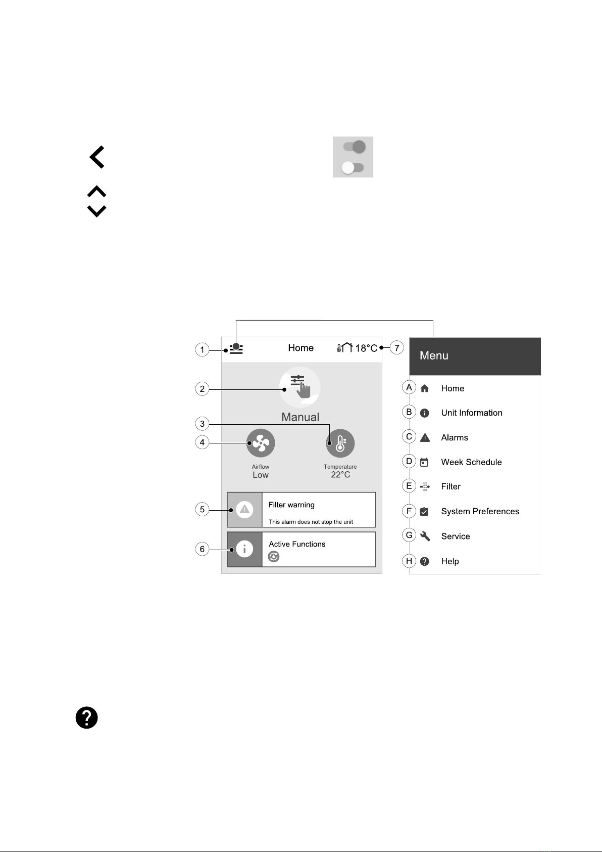
3.2.1 Common symbols . . . . . . . . . . . . .. . . . . . . . . . 4
3.2.2 Home screen overview . . . . . . . . . . . . . . . . 4
3.2.3 Status bar and alarms . . . . . . . . . . . . . . . . . . 4
3.2.4 Quick Information screen . . . . . . . . . . . . . 5
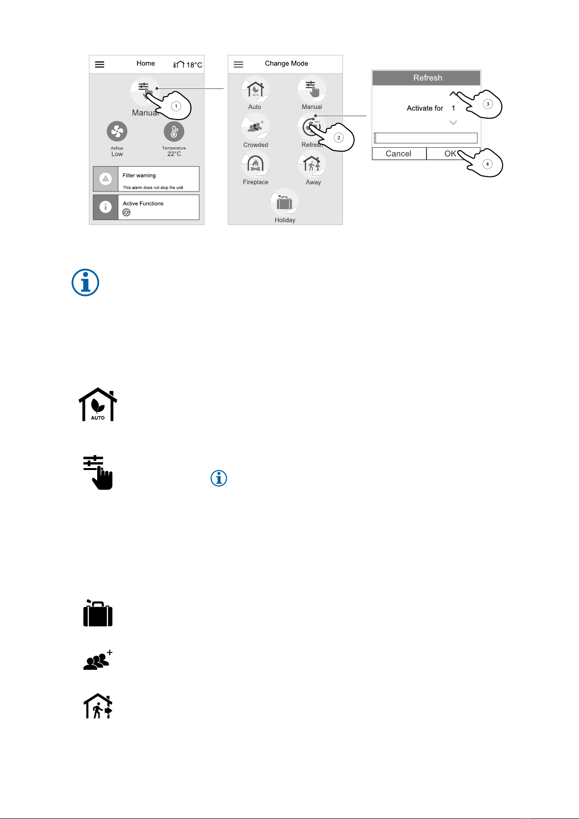
3.2.5 To select user mode. . . . . . . . . . . . . . . . . . . .5
3.2.6 To change the
temperatur e. . . . . . . . . . . . . . . . . . . . . . . . . . .. . . 7
3.2.7 To change the airow. . . . . . . . . . . . . . . . . . 7
3.2.8 To set a week schedule . . . . . . . . . . . . . . .8
4 Maintenance ..................................................9
4.1 Maintenance Schedule . . . . . . . . . . . . . . . . ............9
4.2 To access internal components . . . . . . . . . . . . . . . . 10
4.3 To change lters . . . . . . . . . . . . . . . . . . . . . . . . . .. . . . . . . . 10
4.3.1 To reset the lter change
time ......................................11
4.3.2 To select a dierent lter
kit.........................................11
4.4 To clean the heat exchanger . . . . . . . . . . . . . . . . . .. 11
4.5 To clean fans . . . . . . . . .. . . . . . . . . . . . . . . . . .. . . . . . . . . . . . 12
4.6 Duct System Maintenance . . . . . . . . . . . . . . . . .. . . . . 13
4.6.1 Cleaning extract louvres and
supply air diusers . . . . . . . . . . .. . . . . . . . 13
4.6.2 Checking the outdoor air
intake ....................................13
4.6.3 Checking the roof cowl (if
tted)....................................13
4.6.4 Checking and cleaning the duct
system . . . . . . ............................13
5 Troubleshooting . . . . . . . . . . . . . . .. . . . . . . . . . . . . . . . . .. . . . . . . . . . . 13
6 Electrical data...............................................14
7 Disposal and recy cling . . . . . . . . . . . . . . . . . . . . . . . . .. . . . . . . . . . . 15


Overview |1
1 Overview
1.1 General Description
This manual describes basic information how to operate and perform maintenance on the unit and the system it is con-
nected to.
Read the instructions carefully and in its entirety.
For description of advanced settings and installation of accessories see Service and Accessories Installation manual.
All documents can be found in our online catalogue at www.systemair.com.
1.2 Warranty
For the assertion of warranty claims, the products must be correctly connected and operated, and used in accordance
with the data sheets. Further prerequisites are a completed maintenance plan with no gaps and a commissioning re-
port. Systemair will require these in the case of a warranty claim.
1.3 Type label
Before calling your service representative, make a note of the specification and production number from the type label,
which can be found next to the external connections and inside of the unit.
Fig. 1 Type label
Position Description
1Product code (product specification)
2Product item number
3Production order number
4Serial number
5Production date (YY.MM.DD)
6Scannable code for manufacturing order (MO) number and software version
7Scannable code for the spare parts list and documentation
2 Warnings
Danger
• Make sure that the mains supply to the unit is disconnected before performing any maintenance or
electrical work!
• All electrical connections and maintenance work must be carried out by an authorized installer and in
accordance with local rules and regulations.
254297 | v01

2|Operation
Warning
• This product is not intended to be used by children or people with reduced physical or mental ability or
lack of experience and knowledge, if no instruction concerning the use has been given by the person
responsible for their safety or that this person is supervising the operation. Children should be supervised
so that they can not play with the product.
• Beware of sharp edges during mounting and maintenance. Use protective gloves.
Warning
• Although the mains supply to the unit has been disconnected there is still a risk of injury due to rotating
parts that have not come to a complete standstill.
3 Operation
The unit can be controlled by one or more control methods:
• SAVE LIGHT control panel, refer to 2.
• SAVE TOUCH control panel, refer to 3.
• SAVE CONNECT, refer to 3.
3.1 SAVE LIGHT control panel
Fig. 2 Explanation of symbols
SAVE LIGHT is a basic control panel for SAVE series resi-
dential air handling units. SAVE LIGHT allows to change
airflow levels and indicates when any alarm is present.
1. A button to increase airflow
2. A button to reduce airflow
3. Current airflow level/mode
4. Filter change LED
5. General alarm LED
3.1.1 Indicators
General alarm LED shows when any alarm has occurred. Alarm type is not specified.
It is not possible to acknowledge alarms from the SAVE LIGHT control panel. Please check SAVE TOUCH
control panel or contact your local technical service provider.
The filter change LED shows when filters have to be replaced.
Filters cannot be cleaned and must be changed as necessary. This is normally done 2–3 times per year
depending on the air pollution at the installation site.
3.1.2 To select airflow level
LEDs show current airflow level (figure 2, pos. 3).
• Press button to increase the airflow.
• Press button to decrease the airflow.
254297 | v01

Operation |3
Off Low
(Minimum) Normal High Refresh
(Maximum)
Auto — flashing
slowly
The fan can be
set to Off by
activating
Manual Fan
Stop function in
Service menu.
Fan speed – 25% Fan speed – 45% Fan speed – 70% Sets speed of
both supply and
extract air fans
to Maximum
levels to replace
indoor air with a
fresh air in a
short period of
time.
The unit returns
to previously
active mode
after 1 hour
when in the
Refresh mode.
Automatic
airflow control.
Available only
when Week
Schedule,
Demand
Control
functions are
active or Fan
Control setting
is set to
External.
Note:
•Minimum and Maximum airflow can only be activated by a signal from an external source.
•Auto mode or Manual Fan Stop function can be enabled using the SAVE TOUCH control panel or a
mobile application.
• It is not recommended to set fan to Off in standard households. If manual fan stop is activated, the unit
should be provided with dampers in exhaust and fresh air ducts to avoid cold draught and risk of
condensation when the unit has been stopped.
3.1.3 To cancel sleep mode
Press any button to cancel the sleep mode. SAVE LIGHT returns to the sleep mode after 3 minutes of inactivity.
All control panel lights are off during sleep mode. The sleep mode is active from 9:00 PM to 7:00 AM (based on time of
the air handling unit).
3.1.4 To change control panel address (if more than one control panel is used)
If more than one SAVE LIGHT control panel is used, the address of other control panels must be changed.
Each control panel must have it’s own unique address number. No control panel should have the same address value to
function properly.
1. Push and hold button for 10 seconds to see a current control panel address value.
2. Press button to increase and button decrease the value.
Address value can be changed from 6 to 10, default value is 10.
Address value Indication
6Low airflow LED is on
7Normal airflow LEDs are on
8High airflow LEDs are on
9Refresh mode LEDs are on
10 All LEDs are on
3.2 SAVE TOUCH control panel / SAVE CONNECT
Settings are done by touching the icons or options. The touch screen is sensitive and it is not necessary to press too
hard.
254297 | v01

4|Operation
SAVE CONNECT solution (mobile application and Internet access module) has a similar menu structure and functionality
as SAVE TOUCH control panel, so this section can also be used as a guide for the mobile application.
3.2.1 Common symbols
The following selection symbols are common and are present in most menu pages:
Back button to return to a previous
menu, located at the upper left corner
On and Off slider to activate or
deactivate a function. White bubble —
function is inactive, green bubble —
function is active.
Up arrow to increase a value CANCEL Button to cancel changes
Down arrow to decrease a value SET/OK Buttons to confirm changes
Some menus have more than one page. Touch page indicator in the top right corner to go to the next page. The first
number indicates current page number and the second number indicates a total number of pages available.
Many options show up in a form of the pop-up window. Select the option from the displayed list in the pop-up window
and press OK to confirm selection.
3.2.2 Home screen overview
1. Menu
2. Active user mode
3. Temperature settings
4. Airflow settings
5. Alarms and warnings
6. Status line
7. Outdoor temperature
A.Return to home screen
B. Basic read-only information about the unit
C. Currently active alarms and alarm history
D. Configure and check week schedule
E. Check and change remaining time till filter change
F. General system preferences
G.Configuration of all system parameters
H.Help and troubleshooting menu
3.2.3 Status bar and alarms
Status bar indicates all currently active functions. Touch the status bar to see descriptions of active functions in more
detail.
For more information about user modes and functions, please check Help menu.
Touch the alarm bar on the home screen to see all active alarms.
254297 | v01

Operation |5
Touch HELP button to know more about the alarm. To clear the alarm, touch ACKNOWLEDGE button.
Note:
The underlying cause of the alarm must be resolved first otherwise the alarm will appear again.
If the problem continues contact your installation company or place of purchase.
3.2.4 Quick Information screen
Quick information screen can be shown instead of a sleep
mode screen.
Quick information screen shows the following
information:
1. Time
2. Outdoor temperature
3. Current User mode / Alarm
4. Fan speed
○○○ – off, ●○○ – Minimum/Low, ●●○ – Normal,
●●● – High/Maximum
5. Supply air temperature
6. Relative humidity (if configured)
7. CO2sensor value (if configured)
Quick Information screen can be enabled or disabled in
menu System Preferences —> Display Settings
— > Quick Info screen.
3.2.5 To select user mode
For more information about user modes and functions, please check Help menu.
The top circle on the home screen indicates a currently active user mode. Touch the symbol to change the mode.
254297 | v01

6|Operation
Duration have to be set for temporary user modes. SAVE VTC 300 will return to its previous working mode after the set
time expires.
Note:
AUTO mode is available for selection only if the optional Demand Control,Week Schedule and/or
external fan control functions are activated.
3.2.5.1 Permanent modes
Permanent modes are always active unless interrupted by temporary modes, activated user functions or alarms:
Icon Text Description
Auto
Automatic airflow control. AUTO mode is available for selection when Demand
Control,Week Schedule and/or external fan control functions are configured,
otherwise AUTO mode icon won’t be visible in active user modes menu. AUTO
mode activates Demand Control,Week Schedule and/or external fan control
functions. Demand is available to choose as airflow setting in Week Schedule.
Manual
Manual selection of airflow levels. The unit can be set run at one out of four
available airflow speeds: Off/Low/Normal/High.
Note:
The fan can be set to OFF by activating Manual Fan Stop function in
Service menu.
3.2.5.2 Temporary modes
Temporary modes are active only for a set period of time unless interrupted by active user modes, activated user func-
tions or alarms:
Icon Text Description
Holiday
Sets speed of both supply and extract air fans to Low levels when user is away
from home for a long period of time.
ECO mode is active.
Set duration in days.
Crowded
Sets speed of both supply and extract air fans to maximum High levels and
temperature setpoint offset to –3 K when apartment is more crowded than usual.
Default temperature setpoint offset is –3 K.
Set duration in hours.
Away
Sets speed of both supply and extract air fans to Low levels when user is away
from home for a short period of time.
ECO mode is active.
Set duration in hours.
254297 | v01

Operation |7
Icon Text Description
Refresh
Sets speed of both supply and extract air fans to Maximum levels to replace
indoor air with a fresh air in a short period of time.
Set duration in minutes.
Fireplace
Sets speed of supply air fan to High level and extract air fan to Low level to
increase air pressure within the apartment for better smoke extraction through
the chimney.
Set duration in minutes.
Settings of all modes can be modified in Service menu.
3.2.6 To change the temperature
Touch the thermometer symbol on the home screen to open the temperature settings window.
Use up and down arrows to increase or decrease a value. The default setting is 18 °C.
ECO mode is a power saving function which partially limits heater operation and
can only be activated if a heater is installed.
3.2.7 To change the airflow
Touch the fan symbol on the home screen. In the open window use up or down arrows to increase or decrease the
speed of fans.
Note:
Airflow regulation is available only in Manual mode.
254297 | v01

8|Operation
3.2.8 To set a week schedule
While in home screen, touch menu icon and select Week Schedule.
The menu is locked by default. Enter a password (default password is 1111).
Touch icon at the bottom left corner of the screen to add a new schedule or press EDIT button to modify already added
schedule.
Touch the slider to the right to activate scheduled period.
Set the time. Touch the START TIME or END TIME values to change time. Use arrow buttons and to increase or
decrease value. Confirm with OK button.
Note:
Scheduled time can start but never end at midnight (00:00). The latest END TIME period is 23:59. Scheduled
time cannot go to the next day.
12 or 24 hour time format can be changed in System Preferences menu.
Week Schedule is active only during AUTO mode.
If necessary, activate second scheduled period and set up time.
Once time is set, click on the day(s) when schedule should be active. It is possible to set a separate schedule for each
day. Already scheduled days are not available for selection for new schedules.
Confirm schedule with OK button.
254297 | v01

Maintenance |9
3.2.8.1 To schedule airflow settings
Touch settings icon to go to SCHEDULE AIRFLOW SETTINGS menu. In this
menu set airflow level for scheduled and unscheduled periods. Available lev-
els: Off,Low,Normal,High or Demand.
Set temperature setpoint offset for both periods (-10°C – 0°C).
Demand level is available only if Demand Control or External fan function is active.
4 Maintenance
Danger
• Make sure that the mains supply to the unit is disconnected before performing any maintenance or
electrical work!
Warranty claims can only be made if maintenance work is carried out correctly and written evidence thereof is
provided.
4.1 Maintenance Schedule
Task 6 months 1 year 3 years When necessary
General inspection X
Filter change X X
Fan cleaning X
Heat exchanger cleaning X X
Checking and cleaning louvres/
diffusers
X
Checking and cleaning outdoor air
intake
X
Checking and cleaning roof cowl (if
fitted)
X
Cleaning of duct system X1
1. It is recommended to do this every 5 years and is normally carried out by authorized companies specialized in this area.
• Use original spare parts from Systemair only.
• Scan the code on the type label to find a spare part list.
254297 | v01

10 |Maintenance
4.2 To access internal components
Danger
• Make sure that the mains supply to the unit
is disconnected before performing any
maintenance or electrical work!
Open the hatch with the two latches and swing the hatch
open.
4.3 To change filters
Fig. 3 Changing of filters
The filters cannot be cleaned and must be changed as
necessary. This is normally done 1–2 times per year de-
pending on the air pollution at the installation site.
It is very important to change filters regularly for perform-
ance and energy efficiency of the unit.
Each filter has a label with an part number for identifica-
tion. Provide this number when ordering new filters.
When it’s time to change the filters an alarm is shown on
the control panel display. When this occurs do the
following:
1. Stop the unit by disconnecting the mains.
2. Open the front hatch. See chapter 4.2.
3. Remove old filters and insert new ones. Make sure fil-
ters are not mixed up during the replacement process.
Supply and extract air filters may be different.
4. Close and lock the front hatch and connect the unit to
mains.
5. Reset the filter time. See chapter 4.3.1.
254297 | v01

Maintenance |11
4.3.1 To reset the filter change time
Once filter is changed, it is necessary to reset filter time. Go to Filter menu
(see 3.2.2 Home screen overview, page 4, pos. E) or if filter alarm is present,
click on alarm status line (see 3.2.2 Home screen overview, page 4, pos. 5)
and select filter alarm. Select CHANGE FILTER, in the pop up menu define a
new filter period and press OK to confirm selection.
Filter time is now reset.
Note:
The menu is locked by default. Enter a password (default
password is 1111).
To reset filter change timer for SAVE LIGHT
• Push and hold and buttons for 3 seconds to reset the filter timer
(filter change LED will turn off).
4.3.2 To select a different filter kit
Standard filters are designed for good outdoor air quality. It is possible to se-
lect and order filter kits for poorer air quality environment.
To change filter kit type
1. Touch Select different filter kit button in the alarm menu.
Alternatively, go to Filter menu (3.2.2 Home screen overview, page 4,
pos. E).
2. Select filter kit from the list.
3. Touch OK button.
4.4 To clean the heat exchanger
Danger
• Make sure that the Mains supply to the unit is disconnected before performing any maintenance or
electrical work!
Warning
• Beware of sharp edges during mounting and maintenance. Use protective gloves.
254297 | v01

12 |Maintenance
Fig. 4 Heat exchanger
Even if the required maintenance is carried out, dust will
build up in the exchanger block. It is therefore of vital im-
portance for the upkeep of a high efficiency that the ex-
changer block is removed from the unit and cleaned
periodically as described below. Clean the heat exchanger
at least every 3 years or when required.
1. Stop the unit by disconnecting the mains.
2. Open the front hatch. See chapter 4.2.
3. Pull out the exchanger using the strap at the front.
4. Gently vacuum the heat exchanger.
5. Remount the heat exchanger.
6. Close and lock the front hatch and connect the unit to
mains.
4.5 To clean fans
Danger
• Make sure that the mains supply to the unit is disconnected before performing any maintenance or
electrical work!
Warning
• Risk of injury due to rotating parts that have not come to a complete standstill after mains supply to the
unit have been disconnected.
Warning
• Beware of sharp edges during mounting and maintenance. Use protective gloves.
1 Disconnect the unit from the mains by pulling out the wall plug
2 Remove the cover plates
3 Disconnect the fan power cables. The cables are found beside the fans.
254297 | v01

Troubleshooting | 13
4 Loosen the bracket holding the fan and pull the fan out carefully
5 Clean the fan using a cloth or a soft brush. Do not use water. White spirit
can be used to remove obstinate settlements. Allow to dry properly be-
fore remounting.
4.6 Duct System Maintenance
4.6.1 Cleaning extract louvres and supply air diffusers
The system supplies fresh air to your home and extracts the used indoor air via the duct system and diffusers/louvres.
Diffusers and louvres are mounted in ceilings/walls in bedrooms, living room, wet rooms, WC etc. Remove diffusers
and louvres and wash in hot soapy water as required (diffusers/louvres must not be exchanged). Cleaning of diffusers/
louvres can be done as necessary.
4.6.2 Checking the outdoor air intake
Leaves and pollution could plug up the air intake grille and reduce the capacity. Check the air intake grille, and clean as
necessary. It is recommended to do this at least twice a year.
4.6.3 Checking the roof cowl (if fitted)
The roof cowl (if fitted) connected to the exhaust air duct needs to be checked at least twice a year and cleaned if
necessary.
4.6.4 Checking and cleaning the duct system
Dust and grease deposits may build up in the duct system, even if required maintenance such as changing of filters is
being carried out. This will reduce the efficiency of the installation.
The duct runs should therefore be cleaned/changed when necessary. Steel ducts can be cleaned by pulling a brush
soaked in hot soapy water through the duct via diffuser/louvre openings or special inspection hatches in the duct sys-
tem (if fitted).
It is recommended to do this every 5 years and is normally carried out by authorized companies specialized in this area.
5 Troubleshooting
If problems should occur, please check the items below before calling your service representative.
Fans do not start
1. Check the control panel for alarms.
2. Check that all fuses and fast couplings are connected (main power supply and fast couplings for supply and extract
air fans).
3. Check the week schedule. Fans may be set to OFF in the Schedule airflow settings menu.
Reduced airflow
1. Check the control panel for alarms. Some alarms can reduce the airflow to LOW if active.
254297 | v01

14 | Electrical data
2. The unit could be in defrost mode. This reduces the fan speed and in some cases shuts down the supply air fan com-
pletely during the defrosting cycle. The fans go back to normal after defrosting. There should be a defrosting function
icon visible on the home screen if defrosting is active.
3. Speed of fans is linearly reduced when the outdoor air temperature is below 0°C and an outdoor airflow compensa-
tion function is enabled.
4. Check if temporary user mode that reduces airflow is not activated, for example Away,Holiday, etc. Also check dig-
ital inputs Central Vacuum Cleaner and Cooker Hood.
5. Check the airflow settings in the control panel.
6. Check week schedule settings (chapter 3.2.8).
7. Check filters. Is change of filters required?
8. Check diffusers/louvres. Is cleaning of diffusers/louvres required?
9. Check fans and heat exchange block. Is cleaning required?
10.Check if the buildings air intake and roof unit (exhaust) have been clogged.
11.Check visible duct runs for damage and/or build up of dust/pollution.
12.Check diffuser/louvre openings.
The unit cannot be controlled (control functions are stuck
1. Reset control functions by disconnecting mains power for at least 10 seconds.
2. Check the modular contact connection between the control panel and the main printed circuit board.
Low supply air temperature
1. Check the control panel for alarms.
2. Check the active user functions on the control panel if defrosting function is running.
3. Check set supply air temperature on the control panel.
4. Check if ECO mode is activated on the control panel (it is a power saving function and prevents the heater from
activating).
5. Check if user modes Holiday,Away or Crowded are activated on the control panel or via a hardwired switch.
6. Check the analogue inputs in the service menu to verify that the temperature sensors are functioning correctly.
7. In case of installed electrical/other re-heater battery: Check if the overheat protection thermostat is still active. If
necessary, reset by pressing the red button on the front plate of the electrical re-heater.
8. Check if the extract filter must be changed.
9. Check if the unit has a re-heater battery connected. At very cold outdoor conditions an electrical or water heating
battery might be necessary. A re-heater battery can be acquired as an accessory.
Noise/vibrations
1. Clean fan impellers.
2. Check that the screws holding the fans are tightened.
3. Check that the anti vibration lists are fitted to the mounting bracket and to the back of the unit.
6 Electrical data
Model Fans (W ) Heater (W) Total (W) Fuse (mains) (A)
VTC 300 170 –170 10
VTC 300 with reheater 170 1700 1870 10
Voltage 230V 1~, 50Hz
254297 | v01

Disposal and recycling | 15
7 Disposal and recycling
This product is compliant with the European WEEE Directive and related national waste
legislation. When disposing the unit, follow your local rules and regulations.
This product packing materials are recyclable and can be reused. Do not dispose in household
waste.
254297 | v01

SAVE VTC 300 · User Manual · 254297 · en_GB · 2021-03-15 · v01
Inwest-Klima M. Godlewski, E. Hankowska sp.j
ul. Przędzalniana 8
15-688 Białystok
+ 48 85 662 24 64
biuro@inwestklima.com.pl
www.inwestklima.com.pl
Other manuals for ENERGYSAVING IPCT-350
1
Table of contents
Other InwestKlima Air Handler manuals
Popular Air Handler manuals by other brands

Deekax
Deekax TALTERI DIVK-C 60 CD Installation and user manual

B&D
B&D HSS BDAH-01 installation manual

ActronAir
ActronAir ECOFLEX MINI VRF R-32 Series owner's manual

Dogu
Dogu FourSeason KKS 062 - 046 Installation, operation and maintenance instructions

ViM
ViM KSDR ECOWATT 48 instruction manual

Lennox
Lennox e-MovAir Series Installation & operating manual