22
22
2
CONTENTSCONTENTS
CONTENTSCONTENTS
CONTENTS
GENERAL RECOMMENDGENERAL RECOMMEND
GENERAL RECOMMENDGENERAL RECOMMEND
GENERAL RECOMMENDAA
AA
ATIONSTIONS
TIONSTIONS
TIONS........................................................................................................................................................................................................................................................................
........................................................................................................................................................................................................................................................................
.................................................................................................................................... 33
33
3
SAFETY DIRECTIONS ............................................................................................................................................................................................................................. 3
WARNING ............................................................................................................................................................................................................................................ 3
PRESENTPRESENT
PRESENTPRESENT
PRESENTAA
AA
ATIONTION
TIONTION
TION ....................................................................................................................................................................................................................................................................................................................................
....................................................................................................................................................................................................................................................................................................................................
.................................................................................................................................................................. 44
44
4
WARRANTYWARRANTY
WARRANTYWARRANTY
WARRANTY..................................................................................................................................................................................................................................................................................................................................................
..................................................................................................................................................................................................................................................................................................................................................
......................................................................................................................................................................... 44
44
4
EQUIPMENT SAFETY DEQUIPMENT SAFETY D
EQUIPMENT SAFETY DEQUIPMENT SAFETY D
EQUIPMENT SAFETY DAA
AA
ATT
TT
TAA
AA
A............................................................................................................................................................................................................................................................................................
............................................................................................................................................................................................................................................................................................
.............................................................................................................................................. 55
55
5
INSPECTION AND STINSPECTION AND ST
INSPECTION AND STINSPECTION AND ST
INSPECTION AND STORAORA
ORAORA
ORAGEGE
GEGE
GE ....................................................................................................................................................................................................................................................................................
....................................................................................................................................................................................................................................................................................
.......................................................................................................................................... 66
66
6
CONTENTS OF PCONTENTS OF P
CONTENTS OF PCONTENTS OF P
CONTENTS OF PARCELARCEL
ARCELARCEL
ARCEL ......................................................................................................................................................................................................................................................................................................
......................................................................................................................................................................................................................................................................................................
................................................................................................................................................... 66
66
6
PRODUCT OFFER AND VARIANTSPRODUCT OFFER AND VARIANTS
PRODUCT OFFER AND VARIANTSPRODUCT OFFER AND VARIANTS
PRODUCT OFFER AND VARIANTS ................................................................................................................................................................................................................................................................
................................................................................................................................................................................................................................................................
................................................................................................................................66
66
6
DESCRIPTIONDESCRIPTION
DESCRIPTIONDESCRIPTION
DESCRIPTION........................................................................................................................................................................................................................................................................................................................................
........................................................................................................................................................................................................................................................................................................................................
.................................................................................................................................................................... 77
77
7
CABINET AND FRAME ........................................................................................................................................................................................................................... 7
COMPRESSORS .................................................................................................................................................................................................................................... 7
EVAPORATORS ..................................................................................................................................................................................................................................... 7
CONDENSER BATTERIES ........................................................................................................................................................................................................................ 7
CONDENSER FANS ............................................................................................................................................................................................................................... 7
FAN CONTROLCOMMANDE DES VENTILATEURS ................................................................................................................................................................................... 7
REFRIGERATING CIRCUIT ..................................................................................................................................................................................................................... 7
POWER SUPPLY AND CONTROL BOX ..................................................................................................................................................................................................... 7
TECHNICAL SPECIFICATECHNICAL SPECIFICA
TECHNICAL SPECIFICATECHNICAL SPECIFICA
TECHNICAL SPECIFICATIONSTIONS
TIONSTIONS
TIONS................................................................................................................................................................................................................................................................................
................................................................................................................................................................................................................................................................................
........................................................................................................................................ 88
88
8
REFRIGERANT CHARGE ........................................................................................................................................................................................................................ 8
ÉLECTRIC SPÉCIFICATIONS ................................................................................................................................................................................................................... 8
AERAULIC TECHNICAL SPECIFICATIONS ............................................................................................................................................................................................... 8
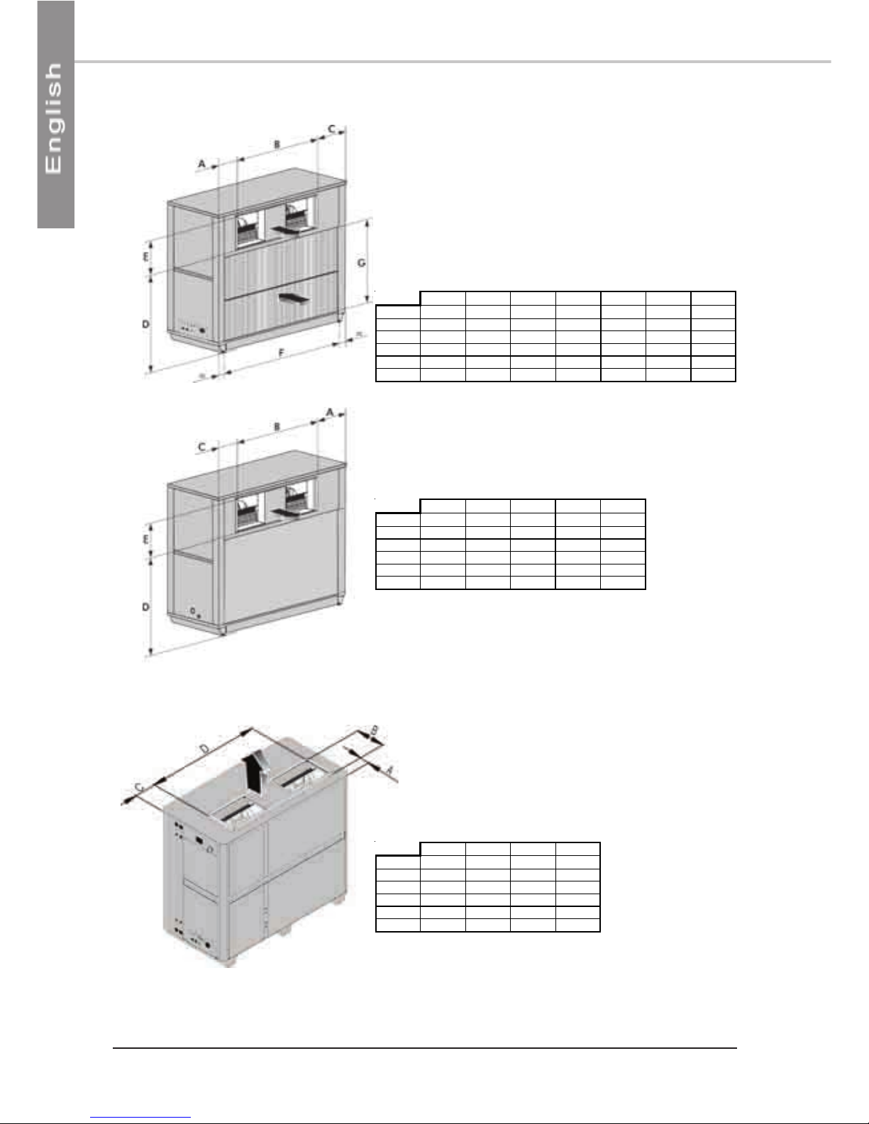
DIMENSIONSDIMENSIONS
DIMENSIONSDIMENSIONS
DIMENSIONS ..........................................................................................................................................................................................................................................................................................................................................
..........................................................................................................................................................................................................................................................................................................................................
..................................................................................................................................................................... 99
99
9
HANDLINGHANDLING
HANDLINGHANDLING
HANDLING..................................................................................................................................................................................................................................................................................................................................................
..................................................................................................................................................................................................................................................................................................................................................
......................................................................................................................................................................... 99
99
9
WEIGHT ............................................................................................................................................................................................................................................... 9
DUCT OUTLET DIMENSIONSDUCT OUTLET DIMENSIONS
DUCT OUTLET DIMENSIONSDUCT OUTLET DIMENSIONS
DUCT OUTLET DIMENSIONS................................................................................................................................................................................................................................................................................
................................................................................................................................................................................................................................................................................
........................................................................................................................................ 1010
1010
10
STANDARD BLOWING ......................................................................................................................................................................................................................... 10
REAR BLOWING .................................................................................................................................................................................................................................. 10
VERTICAL BLOWING ............................................................................................................................................................................................................................ 10
FLFL
FLFL
FLOW RAOW RA
OW RAOW RA
OW RATE / EXTERNAL STTE / EXTERNAL ST
TE / EXTERNAL STTE / EXTERNAL ST
TE / EXTERNAL STAA
AA
ATIC PRESSURETIC PRESSURE
TIC PRESSURETIC PRESSURE
TIC PRESSURE................................................................................................................................................................................................................................
................................................................................................................................................................................................................................
................................................................................................................ 1111
1111
11
INSTINST
INSTINST
INSTALLAALLA
ALLAALLA
ALLATIONTION
TIONTION
TION ..................................................................................................................................................................................................................................................................................................................................
..................................................................................................................................................................................................................................................................................................................................
................................................................................................................................................................. 1111
1111
11
CLEARANCE ....................................................................................................................................................................................................................................... 11
LOCATING THE UNIT ......................................................................................................................................................................................................................... 11
DE-ICING WATER DRAINAGE (AQCH MODELS ONLY) ......................................................................................................................................................................... 12
ANTI-VIBRATION SPRING-MOUNTED PADS INSTALLATION ................................................................................................................................................................... 12
HYDRAULIC CONNECTIONSHYDRAULIC CONNECTIONS
HYDRAULIC CONNECTIONSHYDRAULIC CONNECTIONS
HYDRAULIC CONNECTIONS ..............................................................................................................................................................................................................................................................................
..............................................................................................................................................................................................................................................................................
....................................................................................................................................... 1212
1212
12
HYDRAULIC CIRCUIT DIAGRAM .......................................................................................................................................................................................................... 13
WIRING DIAGRAM AND LEGENDWIRING DIAGRAM AND LEGEND
WIRING DIAGRAM AND LEGENDWIRING DIAGRAM AND LEGEND
WIRING DIAGRAM AND LEGEND ..............................................................................................................................................................................................................................................................
..............................................................................................................................................................................................................................................................
............................................................................................................................... 1414
1414
14
WIRING DIAGRAM ............................................................................................................................................................................................................................. 14
LEGEND ............................................................................................................................................................................................................................................. 14
POWER SUPPLY ........................................................................................................................................................................................................................ 14
WIRING DIAGRAM KEY DESCRIPTIONS .................................................................................................................................................................................... 15
COOLING ................................................................................................................................................................................................................... 15
FAN MOTOR AND THEIR EQUIPMENT .......................................................................................................................................................................... 15
WATER CIRCUIT ........................................................................................................................................................................................................... 15
CONTROL AND REGULATION ..................................................................................................................................................................................... 16
NOT PROVIDED : ......................................................................................................................................................................................................... 16
RANGE AND SETTINGS OF THEMAL PROTECTION / NOMINAL INTENSITY OF THE CONTACTORS (CLASSE AC3) ...................................................................... 16
PRESSOSTATS SETTING ........................................................................................................................................................................................................... 16
MISCELLANEOUS .................................................................................................................................................................................................................... 16
ELECTRICAL CONNECTIONSELECTRICAL CONNECTIONS
ELECTRICAL CONNECTIONSELECTRICAL CONNECTIONS
ELECTRICAL CONNECTIONS ..............................................................................................................................................................................................................................................................................
..............................................................................................................................................................................................................................................................................
....................................................................................................................................... 1717
1717
17
COMMISSIONINGCOMMISSIONING
COMMISSIONINGCOMMISSIONING
COMMISSIONING ....................................................................................................................................................................................................................................................................................................................
....................................................................................................................................................................................................................................................................................................................
.......................................................................................................................................................... 1919
1919
19
PRE-START CHECK LIST ........................................................................................................................................................................................................................ 19
ELECTRICAL CHECK ................................................................................................................................................................................................................ 19
HYDRAULIC CHECKS .............................................................................................................................................................................................................. 19
VISUAL CHECK ........................................................................................................................................................................................................................ 19
DUCTING .............................................................................................................................................................................................................................. 19
OPERATING CHECK LIST .................................................................................................................................................................................................................... 20
GENERAL ................................................................................................................................................................................................................................ 20
PHASE ROTATION PROTECTION .............................................................................................................................................................................................. 20
ELECTRICAL ............................................................................................................................................................................................................................. 20
SET POINTS ................................................................................................................................................................................................................. 20
OPERATING VOLTAGE: ................................................................................................................................................................................................. 20
CONTROL ................................................................................................................................................................................................................... 20
FAN & DRIVE ........................................................................................................................................................................................................................... 20
COMPRESSOR AND REFRIGERATION SYSTEM ........................................................................................................................................................................... 20
HYDRAULIC CIRCUIT ............................................................................................................................................................................................................... 21
FINAL TFINAL T
FINAL TFINAL T
FINAL TASKSASKS
ASKSASKS
ASKS..........................................................................................................................................................................................................................................................................................................................................
..........................................................................................................................................................................................................................................................................................................................................
..................................................................................................................................................................... 2222
2222
22
IN-IN-
IN-IN-
IN-WARRANTY RETURN MAWARRANTY RETURN MA
WARRANTY RETURN MAWARRANTY RETURN MA
WARRANTY RETURN MATERIAL PROCEDURETERIAL PROCEDURE
TERIAL PROCEDURETERIAL PROCEDURE
TERIAL PROCEDURE ............................................................................................................................................................................................................
............................................................................................................................................................................................................
...................................................................................................... 2222
2222
22
SERVICE AND SPSERVICE AND SP
SERVICE AND SPSERVICE AND SP
SERVICE AND SPARE PARARE PAR
ARE PARARE PAR
ARE PARTS ORDERTS ORDER
TS ORDERTS ORDER
TS ORDER ........................................................................................................................................................................................................................................................
........................................................................................................................................................................................................................................................
............................................................................................................................ 2222
2222
22
FINAL CHECK ......................................................................................................................................................................................................................... 22
MAINTENANCEMAINTENANCE
MAINTENANCEMAINTENANCE
MAINTENANCE................................................................................................................................................................................................................................................................................................................................
................................................................................................................................................................................................................................................................................................................................
................................................................................................................................................................ 2323
2323
23
REGULAR MAINTENANCE ................................................................................................................................................................................................................... 23
REMOVAL OF PANELS ......................................................................................................................................................................................................................... 23
FAN DRIVE SYSTEM .............................................................................................................................................................................................................................. 23
COILS ................................................................................................................................................................................................................................................ 23
ELECTRICAL ........................................................................................................................................................................................................................................ 23
REFRIGERATION ................................................................................................................................................................................................................................. 23
SERVICING CHECKLIST ....................................................................................................................................................................................................................... 24
TROUBLE SHOOTROUBLE SHOO
TROUBLE SHOOTROUBLE SHOO
TROUBLE SHOOTINGTING
TINGTING
TING ........................................................................................................................................................................................................................................................................................................
........................................................................................................................................................................................................................................................................................................
.................................................................................................................................................... 2525
2525
25