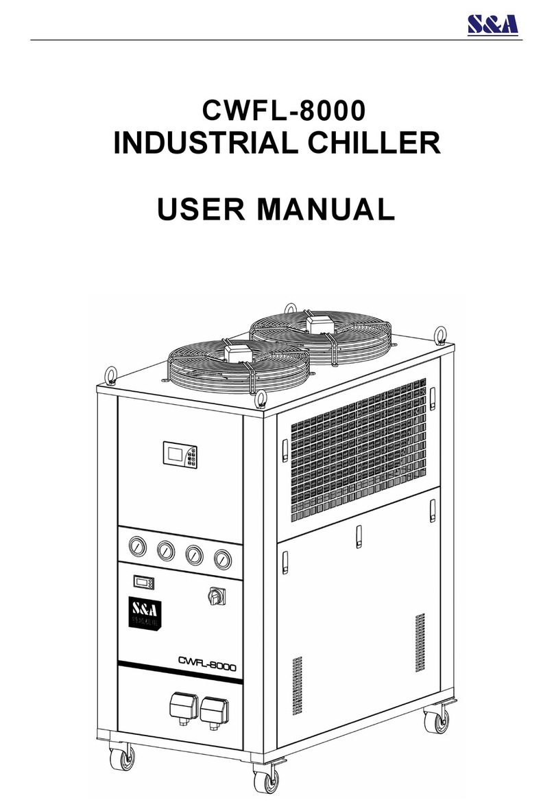
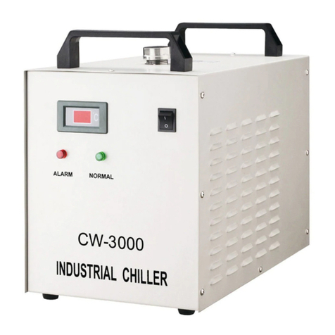
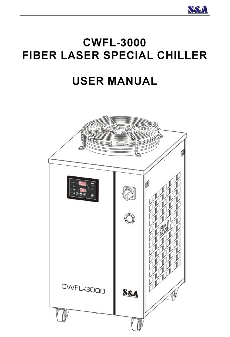
S&A CW-7500 User manual

CW-7500
INDUSTRIAL CHILLER
USER MANUAL

CW-7500 Series
2
Contents
<1> Cautions ----------------------------------------------------------------------------- 3
<2> Contour and parts introduction --------------------------------------------- 4
<3> Installation ------------------------------------------------------------------------- 5
<4> Unit introduction and parameters adjustment ------------------------- 6
<5> Alarm and communication output ----------------------------------------- 12
<6> MODBUS RS-485 communication function ----------------------------- 13
<7> Specifications --------------------------------------------------------------------- 17
<8> Simple troubleshooting -------------------------------------------------------- 18

CW-7500 Series
3
Thank you for using the machine from GUANGZHOU TEYU
ELECTROMECHANICAL CO., LTD. Please read the installation instructions
carefully before installing and operating and keep it properly.
This installation instructions is not a quality assurance. GUANGZHOU TEYU
ELECTROMECHANICAL CO., LTD reserves the right to the interpretation of
correction of typographical errors, improper mentioned information and product
improvement. The amended content will be reprinted in installation instructions
without notice in advance.
<1> Cautions
1. Please ensure that the power supply and electrical outlet are in good contact
and the earth wire must be firmly grounded!
The water chiller installation must be done by professional person in order to
avoid machine damage or accidents by misoperation.
2. Please make sure there is stable and normal voltage for the working chiller!
As the refrigeration compressor is more sensitive to the power supply and
voltage, so the operating voltage of our standard product is ±10 %of the
rated voltage. If you do need a wider operating voltage range, customization
is available for us.
3. Unmatched power frequency can cause the chiller damage!
Please choose model of 50Hz or 60Hz according to actual circumstance.
4. To protect the pump, it’s strictly forbidden to run the chiller without water in
the storage water tank!
The new machine is packed after draining whole water in the tank, so please
make sure the tank has water inside before machine starting, otherwise it’s
easily to have the pump damaged. When the water level is below the green
(NORMAL) range of the water level gauge, the cooling capacity of our chiller
will go down slightly. Hence please ensure the water level is within the green
(NORMAL) range. To drain through circulating pump is strictly prohibited!
5. Please be sure that the air inlet and air outlet are in good ventilation!
There must be at least 100cm from obstructions to the air outlet and at least
50cm between obstructions and the lateral air inlet.
6. Please pay attention to the effect of the condensate water!
With greater ambient humidity, when the water temperature is lower than the
ambient temperature, the condensate water will generate on the surface of
water circular pipes and the cooled components. If above circumstance
appears, it is recommended to set a higher water temperature or keep pipes
and cooled parts warm.
7. Please do turn on the chiller first before turn on the laser machine; turn off the
laser machine first before turn off the chiller.
8. This product is an industrial equipment. For professional use only!

CW-7500 Series
4
<2> Contour and parts introduction
AIR OUTLET
AIR INLET
WATER SUPPLY INLET
WATER INLET
WATER OUTLET
WATER LEVEL GAUGE
WATER DRAIN
WASTE WATER DRAIN
OVERFALL GAP
TEMPERATURE CONTROLLER
WATER PRESSURE
LOW PRESSURE
HIGH PRESSURE
POWER
ALARM AND
COMMUNICATION
OUTPUT
POWER SWITCH

CW-7500 Series
5
<3> Installation
It is very simple to install this industrial cooling machine. The installation for the
first time of the new machine can be carried out by following steps:
1. Open the package to check if the machine is intact and all the necessary
accessories are completed.
2. Open the water supply lid to feed cooling water.
Observing the water level gauge to feed water slowly, be careful not to have
the water overflowed!
3. According to system conditions, please connect the water inlet and outlet
pipe properly.
4. Plug in power, turn on the power switch. (Do not start up without water in the
water tank!)
(1) The water pump starts working once the power switch is turned on. If “E05”
error code is displayed on the upper window of temperature controller, please
adjust the 3-phase wiring connection order
(2) The first time of operating may cause more bubbles in the pipe leading to a
flow alarming occasionally, but running for a few minutes later, it will go back
to normal.
(3) If the chiller starts for the first time, you must immediately check whether the
water pipe leaks.
(4) Power switched on, if the water temperature is under the set value, it is normal
that fans and other components of the machine do not work. The temperature
controller will automatically control the working conditions of the compressor,
magnetic valve, fans and other parts based on the set controlling parameters.
(5) As it takes a longer time to start over the compressor and other components,
according to different conditions, the time is range from seconds to minutes,
so do not turn on and off frequently..
5. Check the water level in the water tank.
The first starting up of a new chiller will empty the air in the water pipe,
causing a slight water level decline, but in order to keep the water level in the
green area, it is allowed to add adequate water again. Please observe and
record the current water level, and inspect it again after the chiller running for
a period of time, if the water level drops obviously, please re-inspect the water
pipeline leakage.
6. Adjust parameters of temperature controller.
CW-7500 series use an new intelligent controller. It works in defaulted
constant temperature control mode for the low temperature end with water
temperature set at 25℃which can be adjusted as needed.
Normally users do not need to adjust the parameters. If it is necessary, please
refer to page 6 , “Unit introduction and parameters adjustment.”

CW-7500 Series
6
<4> Unit introduction and parameters
adjustment
(1) The unit use wire LCD temperature controller to realize more precise
temperature control and stronger capacity of resisting disturbance. It supports
MODBUS-485 communication with transmission distance up to 1.2km;
(2) It has water line anti-icing function. Under standby condition, it functions
when the room temperature is below 5℃;
(3) It has water tank heating function;
(4) It has water line actual flow monitoring function;
(5) It has actual conductivity monitoring function.
1. Temperature control panel introduction and parameters adjustment
(1)The control panel has LCD screen with 7 system operation buttons which
are Language Switching-button (Lang), UP-button (▲), Down-button (▼),
Power-button Set-button (Set), Quick Set-button (Quick Set) and Quit-button
(Quit). Turn off the chiller by pressing the Power-button for 3 sec while other
operations can be completed by short press.
(2) User parameters quick-adjusting: under normal operation condition, press
Quick Set-button to set the user menu. When it displays the set item, press Quick
Set to enter into parameter adjustment interface. Press ▲ or ▼ to to switch the
parameter items. If the parameters need to be modified, press Quick Set-button to
enter into parameter values and press ▲ or ▼ to adjust it. Save the values and
return to parameter quick setting interface by pressing Quit-button when the
adjustment is completed. If there is no more action within 15 sec, it will
automatically exit modifying status with modified parameters saved.
(3) User menu: under normal operation condition, press Set-button for 5 sec
to show user input password interface. Input “168” by pressing ▲ or ▼, then

CW-7500 Series
7
press Set-button to enter into User menu to set the parameters. If the password is
incorrect, it will quit the setting interface and turn to normal operation interface.
The default password 168 must be kept well. The user menu can not be accessed
if the password is forgotten and no backup password is available.
Under user menu, in parameter items interface, press ▲ or ▼ to switch the
items. If the parameters need to be modified, press Set-button to enter into
parameter values and press ▲ or ▼ to adjust it. Save the values and return to
parameter interface by pressing Set-button and press Quit-button to quit the user
menu. If there is no more action within 15 sec, it will automatically exit modifying
status with modified parameters saved.
(4) Check the history failure records: under normal operation condition, press
Set- button and ▲ for 5 sec to access password input interface. Input password
“123” and confirm by pressing Set-button, it will be in failure view status if the
password is correct, if not, it will quit. When the system is under failure records
viewing, it will show the first failure record and code. Press ▲ or ▼ can look over
the failure records and press Quit-button to quit the failure viewing status.
(5) Restore factory settings: under normal operation condition, press and
hold Set-button and Power-button for 10 sec to have the password input
interface popped up then input password “615” to enter into administrator setting
parameters restoration function, and it will display “RECOVERY SUCCESS” and
turn to operation condition after 2 sec. If the password is incorrect, it will quit the
password input interface and turn to operation condition.
(6) Unit operation condition query: the screen will display the operation
conditions of the compressor, water pump and the indoor exhaust temperature
parameters, etc. by pressing Quick Set-button and ▲ at the same time and
release them. Press ▲ or ▼ for page turning and it will automatically exit after
displaying for 5 sec.
(7) Clock adjustment: under normal operation condition, press Quick
Set-button for 5 sec to access clock adjustment interface with time/year flashing.
Press ▲ or ▼ to adjust year and confirm by pressing Quick Set-button; with time
flashing, press ▲ or ▼ to adjust hour and confirm by pressing Quick Set-button;
with minute flashing, press ▲ or ▼ to adjust minute and save the clock setting
by pressing Quick Set- button.
(8) Language switching: the system default language is Chinese. For
switching to English, press Lang-button and the system will change the Chinese
interface to English interface as default language.
(9) Forced refrigeration: under normal operation condition, press ▲ or ▼ at
the same time for 5 sec to activate forced refrigeration function. Press
Power-button can stop the machine and cancel forced refrigeration function.

CW-7500 Series
8
2. Detailed parameter setting is as below table
Orde
r
Code
Set item
Range
Factory
setting
Remark
Register
address
1
F1
Set temp.
F6~F5/
-20~40
25
Intelligent mode /
Constant temp mode
0x0401
2
F2
Temp. difference values
-15~5
-2
0x0402
3
F3
Cooling hysteresis
0.1~3.0
0.8
0.1 resolution ratio
0x0403
4
F4
Way of control
0~1
0
0 Constant,
1 Intelligent
0x0404
5
F5
The highest set temp.
(F6+1)~40
35
Constant temp. mode
0x0405
6
F6
The lowest set temp.
1~(F5-1)
20
Min. 1, Constant
temp. mode invalid
0x0406
7
F7
Ultra-high room temp.alarm
40~50
45
0x0407
8
F8
Ultra-high water temp. alarm
1~20
10
0x0408
9
F9
Ultra-low water temp. alarm
1~20
15
0x0409
10
F10
Temp. alarm delay
0~30
5
Minute
0x040a
11
F11
Sensor failure alarm delay
0~180
10
Second
0x040b
12
F12
Water flow detection delay
of machine startup
0~180
5
Second
0x040c
13
F13
Flow alarm delay
0~180
2
Second
0x040d
14
F14
Heating hysteresis
0~10
0.8
0.1 resolution ratio
0x040e
15
F15
Water pump stop delay
0~180
5
Second
0x040f
16
F16
Startup delay
0~180
30
Second
0x0410
17
F17
Compressor activate
protection
0~180
30
Second
0x0411
18
F18
Turn on setting of phase
sequence protection
On off
On
0x0412
19
F19
Turn on setting of external
input function (startup and
standby)
On off
off
0x0413
20
F20
NO and NC setting of external
input function
NO/NC
NC
NO-normally opened
NC-normally closed
0x0414
21
F21
External input activation delay
0~180
0
Second
0x0415
22
F22
External input standby
activation delay
0~180
0
Second
0x0416
23
F23
Key lock of Chiller On/Off
0-1
1
0:lock
1:unlock
0x0436
24
F24
Self-starting after being
electrified
On off
off
0x043d

CW-7500 Series
9
NOTE:
(1) In parameter setting status, the system runs under original parameters;
(2) Under Constant Temperature control mode (“ F4” set at 0), water
temperature is controlled by “F1”;
(3) Under Intelligent Control mode (“ F4” set at 1), water temperature is
self-adjusting according to ambient temperature. The temperature difference
is controlled by “F2”.
3. Advanced parameters adjustment case
Order
Code
Set Item
Set value in
case 1
Set value in
case 2
Set value in
case 3
T-507 Temp
comptroller
default setting
1
F1
Temperature
setting
28
25
25
2
F2
Temperature
Difference values
-3
-2
3
F3
Cooling
hysteresis
0.5
2.0
1.0
0.8
4
F4
Way of control
1
0
0
0
5
F5
The highest set temp.
31
30
30
35
6
F6
The lowest set temp.
25
5
5
20
7
F7
Ultra-high room temp.alarm
45
45
45
45
8
F8
Ultra-high water temp. alarm
10
5
4
10
9
F9
Ultra-low water temp. alarm
10
10
14
15
10
F10
Temp. alarm delay
5
5
5
5
11
F11
Sensor failure alarm delay
10
10
10
10
12
F12
Water flow detection delay
of machine startup
5
5
5
5
13
F13
Flow alarm delay
2
2
2
2
14
F14
Heating hysteresis
0.8
0.8
0.8
0.8
15
F15
Water pump stop delay
5
5
5
5
16
F16
Startup delay
30
30
30
30
17
F17
Compressor activate
protection
90
90
90
90
18
F18
Turn on setting of phase
sequence protection
/
/
/
/
19
F19
Turn on setting of external
input function
(startup and standby)
off
off
off
off
20
F20
NO and NC setting of external
NC
NC
NC
NC

CW-7500 Series
10
Case 1: cooling water temperature is controlled by intelligent mode.
Requiring water temperature to be between 25℃to 31℃. When the set water
temperature is 3 ℃lower than the ambient temperature and ambient
temperature remains steady, the fluctuation will not exceed ±0.5℃. There will
be an alert when water temperature is 10℃lower or higher than target. (e.g.
when ambient temperature is 30.0 ℃, cooling water temperature is between
27.5℃to 26.5℃, if ambient temperature is up to 30.5 ℃, water temperature
will be between 28.0℃to 27.0℃.)
Case 2: cooling water temperature is controlled by constant mode. Requiring
water temperature is constant at 28℃, and the fluctuate does not exceed ±2℃.
The ultrahigh water temperature alarm will be on when water temperature is
5℃higher than normal temperature, and the ultralow water temperature
alarm will be on when water temperature is 10 ℃lower than normal
temperature.
Case 3: cooling water temperature is controlled by constant mode. Requiring
water temperature is constant in 25℃, and the fluctuate does not exceed ±1℃.
The ultrahigh water temperature alarm will be on when water temperature is
higher than 30 ℃, and the ultralow water temperature alarmwill be on when
water temperature is lower than 10 ℃. (No matter what is the ambient
temperature, the cooling water temperature is constant between 24.0℃and
26.0℃)
4. Failure warning processing mode
When alarm occurs, the failure alarm code will be displayed on the upper right
corner of the LCD screen. In alarming state, the alarm sound could be
suspended by pressing any button, but the alarm display remains until the
alarm condition is eliminated.
input function
21
F21
External input activation delay
0
0
0
0
22
F22
External input standby
activation delay
0
0
0
0
23
F23
Key lock of Chiller On/Off
1
1
1
1
24
F24
Self-starting after being
electrified
off
off
off
off

CW-7500 Series
11
5. Failure code table
Failure
code
Description
Alarm
phenomenon
Alarm action
Elimination
method
E00
Communication
failure alarm
E00 shown with
alarm sound
None
Automatic clearing
after mainboard
and operation panel
are connected well
E01
flow alarm
E01 shown with
alarm sound
The compressor, condenser fans and
heater shut down
Automatic clearing
E02
Ultra-high room
temp.alarm
E02 shown with
alarm sound
Each refrigeration part runs under
usual procedures
Automatic clearing
E03
ultra-low water temp
alarm
E03 shown with
alarm sound
The compressor, condenser fans and
heater shut down
Automatic clearing
E04
ultra-low water temp
alarm
E04 shown with
alarm sound
Each refrigeration part runs under
usual procedures
Automatic clearing
E05
Wrong phase and
lacking phase alarm
E05 shown with
alarm sound
The water pump, compressor,
condenser fans and heater shut down
Manual clearing
E06
Compressor overload
alarm
E06 shown with
alarm sound
The compressor, condenser fans and
heater shut down
Manual clearing
E07
water pump overload
alarm
E07 shown with
alarm sound
The water pump, compressor,
condenser fans and heater shut down
Manual clearing
E08
Refrigeration system
high pressure alarm
E08 shown with
alarm sound
The compressor and condenser fans
shut down
Manual clearing
E09
Refrigeration system
low pressure alarm
E09 shown with
alarm sound
The compressor and condenser fans
shut down
Automatic clearing
E10
Room temp. sensor
failure alarm
E10 shown with
alarm sound
Switched to constant temp. mode and
each refrigeration part runs under
usual procedures
Automatic clearing
E11
water temp. sensor
failure alarm
E11 shown with
alarm sound
The water compressor, condenser
fans and heater shut down
Automatic clearing
E12
Ultra-low water level
alarm
E12 shown with
alarm sound
The unit runs normally under set
values; the water pump, compressor,
condenser fans and heater shut down
Automatic clearing
E13
Exhaust temp. sensor
failure alarm
E13 shown with
alarm sound
Each refrigeration part runs under
usual procedures
Automatic clearing
E14
Ultra-high exhaust
temp. alarm
E14 shown with
alarm sound
Each refrigeration part runs under
usual procedures
Automatic clearing

CW-7500 Series
12
<5> Alarm and communication output
For ensuring the equipment will not be damaged when abnormal condition
occurs in the chiller, it has alarm protection function.
1. Alarm and MODBUS RS-485 communication output wiring diagram.
2. Working condition table of alarm signal
Unit condition
Built-in buzzer of
temp. controller
OUT
H1、H2
OUT
H1、H3
ILUS
Working normally
No Sound
Disconnection
Breakover
E00、E01、E05、E06、
E07、E08、E09、E11
Sounds
Breakover
Disconnection
E02、E10、E13、E14
Sounds
Disconnection
Breakover
E03、E04
Sounds
Breakover
Disconnection
Optional
E12
Sounds
Breakover
Disconnection
Activate after
output terminal
delaying
Note: The flow alarm is connected to the normally open relay and normally closed
relay contacts, requiring operating current less than 5A, working voltage
less than 300V.

CW-7500 Series
13
<6> MODBUS RS-485 communication
function
This system adapts salve mode of MODBUS-RTU communication,9600 baud rate,
no parity checking,8 data bit,1 stop bit and support MODBUS-RTU 03 (Read
Holding Registers) and 06 (Read Holding Registers) commands. Communication
formats are as below:
1. Command format 03
Host send command
Function code
1 bytes
0x03
Initial address
2 bytes
From 0x0400 to 0x044a, From 0x0100 to 0x0108,
From 0x0800 to 0x0803
Register number
2 bytes
From 1 to 10
Slave response
Function code
1 bytes
0x03
Number of bytes
1 bytes
2*N("N" is the number of registers )
Register value
N*2 bytes
Error
For example: if the host’s sending address is 1, requests 108-110 command of
slave read register and send 01 03 00 6B 00 03 XX YY,thereinto,01 as slave
address, 03 as function code, 00 6B as initial address, 00 03 as register number
and XX YY as the result of CRC verification.
Slave response: 01 03 06 02 2B 00 00 00 64 XX YY, thereinto, 01 as slave address,
03 as function code, 06 as number of bytes, 02 2B 00 00 00 64 corresponding to
the values in 108-110 of register respectively and XX YY as verification code.
If the slave receives wrong data, return to data 01 83 01 XX YY, thereinto, 01 as
slave address. 83 as error code, 01 as exception code and XX YY as check sum.
2. Command format 06
Host send command
Function code
1 bytes
0x06
Register address
2 bytes
From 0x0400 to 0x044a
Register value
2 bytes
From 0x000 to 0xffff
Error code
1 bytes
0x83
Exception code
1 bytes
01 or 02 or 03 or 04

CW-7500 Series
14
Slave response
Error
For example: if the host’s sending address is 1, requests command of writing data
00 03 to register 2. Host send: 01 06 00 02 00 03 XX YY, thereinto, 01 as slave
address, 06 as function code, 00 02 as register address, 00 03 as written data and
XX YY as verification code.
Slave response: 01 06 00 02 00 03 XX YY, thereinto, 01 as slave address, 06 as
function code, 00 02 as register address, 00 03 as written data and XX YY as CRC
verification code.
If there is data error or communication exception, send 01 86 02 XX YY.
3. Read only parameter(sensor, current)
Read-only
Register
address
Description
Range
Default
Unit
Data
resolution
Symbol
0x0100
Room temp. sensor
temperature
-25 ~
100
℃
0.1/bit
yes
0x0101
Water temp. sensor
temperature(Low temp)
-25 ~
100
℃
0.1/bit
yes
0x0102
Water temp. sensor
temperature(High temp)
-25 ~
100
℃
0.1/bit
yes
0x0103
Compressor exhaust
temperature
-25 ~
140
℃
0.1/bit
yes
0x0104
Flow of the first waterway
0.1-200
L/Min
0.1/bit
yes
0x0105
Flow of the second waterway
0.1-200
L/Min
0.1/bit
yes
0x0105
Conductivity
0.1-500
μs/cm
0.1/bit
yes
0x0106
Compressor current
(Three-phase average)
0-50
A
0.1/bit
yes
0x0107
Low temp. water pump current
0-50
A
0.1/bit
yes
0x0108
High temp. water pump current
0-50
A
0.1/bit
yes
Function code
1 bytes
0x86
Register address
2 bytes
From 0x0400 to 0x044a
Register value
2 bytes
From 0x000 to 0xffff
Error code
1 bytes
0x86
Exception code
1 bytes
01 or 02 or 03 or 04

CW-7500 Series
15
4. Read only parameter(state)
Read-only
Register
address
Description
Bit definition
0x0800
Relay output
status
MSByte
Bit7(MSb)
Retain
Bit6
Retain
Bit5
Retain
Bit4
Retain
Bit3
Retain
Bit2
Alarm output relay
0:Off 1:On
Bit1
Conductivity lower limit relay
0:Off 1:On
Bit0(LSb)
High temp. heating rod
0:Off 1:On
LSByte
Bit7(MSb)
High temp. water pump relay
0:Off 1:On
Bit6
High temp. refrigeration relay
0:Off 1:On
Bit5
Compressor crankcase
heating
0:Off 1:On
Bit4
Low temp. heating rod
0:Off 1:On
Bit3
Low temp. refrigerant
solenoid valve
0:Off 1:On
Bit2
Condensing fan
0:Off 1:On
Bit1
Compressor relay
0:Off 1:On
Bit0(LSb)
Low temp. water pump
0:Off 1:On
0x0801
Digital input
switch status
MSByte
Bit7(MSb)
Retain
Bit6
Retain
Bit5
Retain
Bit4
Retain
Bit3
Retain
Bit2
Retain
Bit1
Retain
Bit0(LSb)
Retain
LSByte
Bit7(MSb)
Retain
Bit6
Retain
Bit5
External input
0:No input 1:Input
Bit4
Refrigerant low pressure
0:No input 1:Input
Bit3
Refrigerant high pressure
0:No input 1:Input
Bit2
Spare 2
0:No input 1:Input
Bit1
Spare 1
0:No input 1:Input
Bit0(LSb)
Water level
0:No input 1:Input

CW-7500 Series
16
0x0802
Alarm status
(high 16-bit)
MSByte
Bit7(MSb)
Retain
Bit6
Retain
Bit5
Retain
Bit4
Retain
Bit3
Retain
Bit2
Retain
Bit1
Retain
Bit0(LSb)
Retain
LSByte
Bit7(MSb)
Write administrator
parameter error
0:Correct 1:Error
Bit6
Write user parameter error
0:Correct 1:Error
Bit5
Ultra-high exhaust temp.
alarm
0:No alarm 1:Alarm
Bit4
Exhaust temp. sensor failure
alarm
0:No alarm 1:Alarm
Bit3
Ultra-low water temp alarm
0:No alarm 1:Alarm
Bit2
Ultra-low conductivity alarm
0:No alarm 1:Alarm
Bit1
Ultra-high conductivity alarm
0:No alarm 1:Alarm
Bit0(LSb)
High temp. system water
temp. sensor failure alarm
0:No alarm 1:Alarm
0x0803
Alarm status
(low 16-bit)
MSByte
Bit7(MSb)
Low temp. system water
temp. sensor failure
0:No alarm 1:Alarm
Bit6
Room temp. sensor failure
0:No alarm 1:Alarm
Bit5
Refrigeration system low
pressure
0:No alarm 1:Alarm
Bit4
Refrigeration system High
pressure
0:No alarm 1:Alarm
Bit3
High temp. water pump
overload
0:No alarm 1:Alarm
Bit2
Low temp. water pump
overload
0:No alarm 1:Alarm
Bit1
Compressor overload
0:No alarm 1:Alarm
Bit0(LSb)
Wrong phase and lacking
phase
0:No alarm 1:Alarm
LSByte
Bit7(MSb)
High temp. system ultra-high
water temp
0:No alarm 1:Alarm
5. Read/Write Registers(Use only when the external input
function is turned off)
Register address
Description
Range
Default
Unit
Remark
Symbol
0x0804
Chiller On/Off
0-1
--
0:On,1:Off
No

CW-7500 Series
17
<7> Specifications
CW-7500
Note: ①the cooling capacity is under 30℃water temperature and 40℃ambient
temperature working conditions with standard voltage.
②The max. pump flow is obtained by testing the pump individually on test criteria
GB/T 3216-2005.criteria GB/T 3216-2005.
Model
CW-7500EN
CW-7500FN
CW-7500VN
CW-7500HN
Voltage
AC 3P 380V
AC 3P 380V
AC 3P 415V
AC 3P 220V
Frequency
50Hz
60Hz
50Hz
60Hz
Current
8~13A
8~15A
8~13A
4.1~23.6A
Compressor
power
4.95KW
4.54KW
4.95KW
4.70KW
6.73HP
6.05HP
6.73HP
6.39HP
Nominal
cooling
capacity①
49474 Btu/h
47765 Btu/h
49474 Btu/h
49133 Btu/h
14.5 KW
14 KW
14.5 KW
14.4 KW
12467Kcal/h
12039Kcal/h
12467Kcal/h
12381 Kcal/h
Refrigerant
R-22 / R407c
R-22 / R407c
R-22 / R407c
R407c
Refrigerant
charge
4400g
3800g
4400g
3600g
Precision
±1℃
Reducer
Capillary
Protection
Overcurrent protection for compressor, flow alarm, over temperature alarm
Pump power
0.37~1.1KW
Tank capacity
75L
Inlet and outlet
Rp 1’’
Max. lift
28~53M
Max. flow②
70~116 L/min
N.W
325Kgs
G.W
410Kgs
Dimension
129 X70 X 149 cm (L X W X H)
Package
dimension
145 X 92X 178 cm (L X W X H)

CW-7500 Series
18
<8>Simple troubleshooting
Failure
Failure Cause
Approach
Machine turned on but
unelectrified
Power cord is not plugged in place
Check and ensure the power interface and
the power plug is plugged in place and in
good contact
Fuse burnt-out
Open the electric box cover, check the
protective tube, replace with spare one if
necessary and check whether the power
supply voltage is stable; Check and ensure
the power interface and the power plug are
in good contact
Flow Alarm(controller displays
E01) use a water pipe directly
connect to the water outlet and
inlet but still without water
flowing
Water level in the storage water tank is
too low
Check the water level gauge display, add
water until the level shown in the green
area; And check whether water circulation
pipe leaks
Flow alarm occurs while
running with other equipment
(controller displays E01), but
there is water flowing and no
alarm when use a water pipe
directly connected to the chiller
water outlet and inlet
Water circulation pipes are blocked or a
pipe bending deformation.
Check water circulation pipe
Ultra-high temperature alarm
(controller displays E04)
Blocked dust gauze, bad thermolysis
Unpick and wash the dust gauze regularly
Poor ventilation for air outlet and inlet
To ensure a smooth ventilationfor air outlet
and inlet
Voltage is extremely low or astable
To improve the power supply circuit or use
a voltage regulator
Improper parameter settings on
thermostat
To reset controlling parameters or restore
factory settings
Switch the power frequently
To ensure there is sufficient time for
refrigeration (more than 5 minutes)
Excessive heat load
Reduce the heat load or use other model
with larger cooling capacity
Alarm for ultra-high room
temperature
(controller displays E02)
The working ambient temperature is too
high for the chiller
To improve the ventilation to guarantee
that the machine is running under 40℃
Serious problem of condensate
water
Water temperature is much lower than
ambient temperature, high humidity
Increase water temperature or to preserve
heat for pipeline
Water drains slowly from outfall
during water changing
Injection port is not open
Open the injection port

CW-7500 Series
19
CW-7500
工业循环冷水机
使用安装说明书

CW-7500 Series
20
目 录
一、使用注意事项 ----------------------------------------------------------------- 21
二、外形及部件名称 -------------------------------------------------------------- 22
三、安装说明 ----------------------------------------------------------------------- 23
四、机组介绍与参数调整 -------------------------------------------------------- 24
五、报警与通讯输出 -------------------------------------------------------------- 29
六、MODBUS RS-485 通讯功能 ---------------------------------------------- 30
七、技术参数 ----------------------------------------------------------------------- 33
八、简单故障处理 ----------------------------------------------------------------- 34
Table of contents
Other S&A Chiller manuals

S&A
S&A CW-5000AG User manual

S&A
S&A CWFL-500 User manual

S&A
S&A CW-6080 User manual

S&A
S&A CW-5000 Series Installation instructions

S&A
S&A CW-5300 User manual

S&A
S&A CW-3000 Series User manual

S&A
S&A CWFL-4000 User manual

S&A
S&A CW-5300 User manual

S&A
S&A CW-6000AN250S01 User manual

S&A
S&A CWFL-3000 User manual
Popular Chiller manuals by other brands

Electrolux
Electrolux KBB5X operating instructions

Arktic
Arktic 236123 user manual

Daikin
Daikin EWAP800AJYNN Installation, operation and maintenance manual

Acson international
Acson international AMAC40C Technical manual

Clint
Clint MultiPower CHA 726-P manual

Elkay
Elkay EDF14C Installation, care & use manual