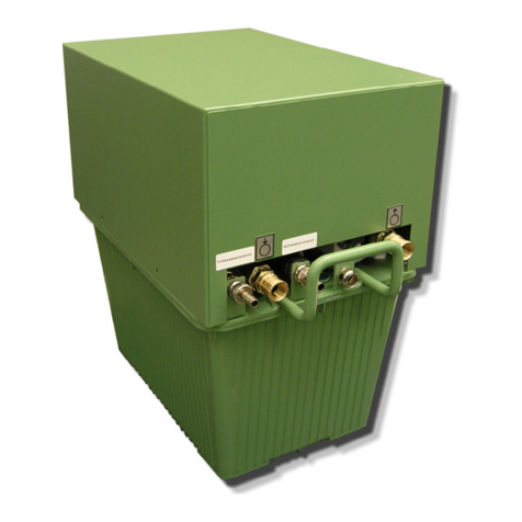
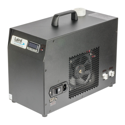
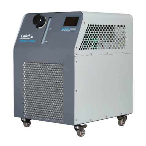
Laird Nextreme NRC400 Installation instructions

Nextreme™Thermoelectric
Chiller, NRC400
Specification and User Manual

2
www.lairdthermal.com
Any information furnished by Laird and its agents, whether in specifications, data sheets, product catalogues or otherwise, is believed to be (but is not warranted as being) accurate and
reliable, is provided for information only and does not form part of any contract with Laird. All specifications are subject to change without notice. Laird assumes no responsibility and
disclaims all liability for losses or damages resulting from use of or reliance on this information. All Laird products are sold subject to the Laird Term
limited warranty) in effect from time to time, a copy of which will be furnished upon request.
Trademarks
© Copyright 2021
subsidiaries.

3
Table of Content
Table of Content.................................................................................................................................. 3
1. Revision History.......................................................................................................................... 5
2. Introduction................................................................................................................................. 6
3. Safety Precautions...................................................................................................................... 7
3.1 Guidelines for Safe Operation.................................................................................................... 7
3.1.1 Prevent Hazards .................................................................................................................. 7
3.1.2 Personal Protective Gear.....................................................................................................7
3.1.3 Guidelines Regarding Electrical Equipment.........................................................................8
3.1.4 Inadmissible Operating Conditions.......................................................................................8
3.1.5 Specialized Knowledge........................................................................................................8
3.2 Safety and Signaling Equipment Included in the Unit.................................................................9
3.3 Guards.......................................................................................................................................9
3.4 In Case of Accidents................................................................................................................10
3.5 Environmental Issues............................................................................................................... 10
4. Model Number Description ...................................................................................................... 11
5. Specifications............................................................................................................................ 12
6. Component Locations.............................................................................................................. 13
7. Labels and Markings ................................................................................................................ 14
8. Transport, Packaging and Storage.......................................................................................... 15
8.1 Safety....................................................................................................................................... 15
8.2 Checking the Delivery Condition.............................................................................................. 15
8.3 Symbols on the Packaging.......................................................................................................15
8.4 Packaging ................................................................................................................................ 16
8.5 Unpacking................................................................................................................................ 16
8.6 Handling the Unit While in the Packaging................................................................................17
8.7 Storing the Unit ........................................................................................................................ 17
8.8 Preparing the Unit for Further Transport .................................................................................. 17
8.8.1 Transporting the Unit (after use) ........................................................................................ 17
9. Installation Requirements........................................................................................................ 19
10. Installation Procedure........................................................................................................... 20
10.1 Connect Hoses....................................................................................................................... 20
10.2 Disconnect Hoses..................................................................................................................21
10.3 Connecting Power..................................................................................................................22
10.4 Adding Coolant and Priming Unit........................................................................................... 22
11. Performance Graphs............................................................................................................. 25
11.1 Thermal Performance ............................................................................................................25
11.2 Pump Performance................................................................................................................ 27
12. Chiller Dimensions................................................................................................................ 28
13. Controller Display Panel Functions..................................................................................... 29

4
13.1 Startup Screen.......................................................................................................................29
13.2 Main Screen...........................................................................................................................29
13.2.1 Running the Pump ...........................................................................................................30
13.2.2 Choosing the Coolant Setpoint.........................................................................................30
13.2.3 Running the system ......................................................................................................... 30
13.3 Sleep Screen.......................................................................................................................... 31
13.4 Information Screen.................................................................................................................31
13.5 Alarms Display Screen...........................................................................................................32
13.5.1 Acknowledging Alarms.....................................................................................................32
13.6 Settings Screen......................................................................................................................33
13.6.1 Setting Units..................................................................................................................... 33
13.6.2 Choosing the Coolant....................................................................................................... 33
13.6.3 Boost mode......................................................................................................................34
13.6.4 Customer Configurable Alarms........................................................................................34
13.7 Setting Offset .........................................................................................................................36
14. Troubleshooting.................................................................................................................... 36
15. Alarms.................................................................................................................................... 38
16. Communications Interface................................................................................................... 40
16.1 Instructions for Setup ............................................................................................................. 40
16.2 Commands and responses: ................................................................................................... 40
17. System Maintenance and Service........................................................................................ 41
17.1 Safety.....................................................................................................................................41
17.2 Maintenance Schedule........................................................................................................... 42
17.3 Preparing the Unit for Maintenance........................................................................................42
17.4 Verification of Safe State after Maintenance..........................................................................43
17.5 Draining Procedure................................................................................................................ 44
17.6 Coolant Maintenance............................................................................................................. 44
17.7 Cleaning the Heat Exchanger ................................................................................................ 44
18. Spare Parts............................................................................................................................ 46
19. Decommissioning and Disposal.......................................................................................... 47
20.1 Temporarily Placing Out of Operation....................................................................................47
20.2 Returning the Unit to Service After Decommissioning............................................................47
20.3 Final Decommissioning or Disposal.......................................................................................47
20.4 Disposal of Operating Materials............................................................................................. 47
20.5 Return of the Unit to Laird......................................................................................................48
20. Return Procedure.................................................................................................................. 49
21. List of figures ........................................................................................................................ 50

5
1. Revision History
User Manual Part Number: 387009443
REV
DATE
DESCRIPTION
00
06/30/2022
Initial release

6
2. Introduction
The Nextreme NRC400 is a new generation recirculating chiller designed for precise temperature
control of analytical instrumentation, industrial lasers and imaging. The NRC400 is a thermoelectric-
based recirculating chiller with few moving parts offering solid-state construction and high reliability. It
is also environmentally friendly as no hazardous refrigerants are used. Innovating heat dissipation
technologies in conjunction with optimized thermoelectric cooler modules have been incorporated into
the design to offer a compact solution with high cooling capacity. The pump offers sufficient flow with
low pulsation for low pressure drop applications and uses ceramic bearings to assure long life
operation.
This chiller offers an LCD touchscreen display for easy user interface to set temperature, alarm
features and monitor coolant supply temperature. The programmable alarm offers freeze protection
and can alert users when fluid level falls below normal operating conditions. If a critical component
fails, such as the fan or pump, the unit will operate in a safe mode. This NRC400 uses a semi-closed
system with a large reservoir tank to reduce the coolant maintenance and comes with quick
disconnect liquid connections to simplify hood up to supply line.
This user manual provides necessary information to the customer for proper installation, operation,
communication, and maintenance of the chiller.

7
3. Safety Precautions
This section provides an overview of all the important safety aspects for optimal protection of
personnel as well as safe and trouble-free operation of the equipment.
The operating manual and warning instructions specified herein should be reviewed completely by all
personnel prior to operating the unit. Disregarding instructions within this manual may result in
considerable danger.
3.1 Guidelines for Safe Operation
3.1.1 Prevent Hazards
Hazards can be prevented by safety-conscious and anticipatory behavior of staff. Individuals working
with the unit should keep the following in mind:
▪Always keep a complete and legible copy of this operating manual (or the location at which it can
be found) available at the installation site of the unit.
▪Use personal protection equipment.
▪Unit personnel must be familiar with all operating elements of the unit before starting work on the
unit.
▪Only use the unit for its intended purpose.
▪Conduct inspections on a regular basis and ensure the unit is operational and free of damage.
▪All unit warning and information signs must be kept in legible condition. If a warning or
information sign is lost or illegible, it must be replaced.
▪Unit repairs may be carried out by qualified personnel only.
▪Any disruption or recognizable change concerning the unit should be reported to the responsible
person.
▪Adhere to the accident prevention regulations as well as any regional regulations.
3.1.2 Personal Protective Gear
To minimize health hazards, wearing personal protective gear is required when handling the unit. The
following personal protective gear must always be worn when handling the unit:
Protective footwear
For protection from falling parts and to prevent slipping.
When cleaning or performing maintenance or repair work on the unit, the following specific personal
protective gear is required:
Protective gloves
To protect the hands from rubbing, abrasions, cuts, or more serious injuries. To prevent burns when
touching hot coolant.
Protective eyewear
To protect the eyes against flying parts or splashing coolant.

8
3.1.3 Guidelines Regarding Electrical Equipment
DANGER
Electrical danger
Work on electrical installations must be carried out only by trained and authorized
electricians.
▪Observe all regional regulations when connecting electrical equipment to mains. Be
aware of the connection diagram information.
▪Electrical shock hazards exist if the electrical installations are defective or the
insulation fails during operation.
▪Switch off and disconnect the unit from the electrical mains and follow Lockout-Tagout
procedures whenever conducting service work.
▪Ensure continuity to ground and isolation from power lines.
▪Any changes regarding the operation of the unit can have an influence on safe
operation. All intended changes should be authorized by the manufacturer prior to
implementation.
▪Keep unauthorized persons away from the working area.
3.1.4 Inadmissible Operating Conditions
Operating the unit under improper conditions is not permitted as the operat safety cannot be
guaranteed. Some operating conditions not permitted are the following:
▪Using the unit for a purpose other than its intended use
▪Using of the unit when any part of it is damaged, not working properly, the electrical installation is
not correct, or the electrical insulation is damaged
▪Protective or safety equipment is non-functional, defective, improperly installed, or missing
▪The unit or operating parameters were modified without consulting the manufacturer
▪Operation in areas exposed to explosion hazards
▪Operation without a cooling media not recommended by the manufacturer
▪Any equipment connected to RS232 must be certified to IEC 61010-1/ IEC 60950-1/ IEC 62368-
1 should be connected to the DB-9 port.
▪Only Laird approved cable must be used to connect Flow meter to the unit. Refer to Spare Parts
to order this cable.
▪High Temperature Limit on Coolant Return - The maximum allowable coolant return (inlet) is
50°C. It is the responsibility of the customer to ensure that this limit is not exceeded. Laird
Thermal Systems recommends a thermal shutoff be used in conjunction with the equipment
being connected to the Recirculating Chiller. Methods include:
oA method to turn off the heat load from injecting additional heat into the coolant. This
will allow the Recirculating Chiller to reduce the temperature of the coolant further
until stable.
oA method that stops or restricts the coolant flow into the Recirculating Chiller. This will
result in a Coolant High Pressure alarm, which will shut down the system for safety.
oA method that interrupts the power to the Recirculating Chiller.
If any of these methods are activated, please reference the Alarms section.
NOTE
The manufacturer is not liable for damage occurring when using the unit in a way it was not
intended. warranty.
3.1.5 Specialized Knowledge
NOTE
Authorized persons
Servicing the unit is limited to individuals with adequate knowledge and training pertaining to the
required area of service. In some circumstances licensed professionals are required to perform the
required service work.

9
The activities listed Table 1 in may only be performed by personnel with specialized knowledge.
Table 1: Activities and specialized knowledge
Activities
Qualifications
Working on mechanical and / or
hydraulic installations
Industrial technician or sufficiently instructed personnel who can work on
installation instructions
Working on electrical installations
and equipment
Skilled and licensed electrician
Working on refrigeration
components and systems
Skilled and licensed refrigeration technician
3.2 Safety and Signaling Equipment Included in the Unit
The unit is equipped with the following safety equipment:
▪The minimum coolant level in the system is detected by a low fluid levelalarm condition
triggered by an
on the front of the chassis, the controller shuts off the entire unit.
▪Controller has a freeze protection incorporated into the LCD. The default temperature selection
that can be made is only 10C to 40C, when the coolant selected by the customer is water
(default). Depending on the other coolant options selected the setpoint temperature can be
selected to below 10C value. More details are given under Choosing the Coolant
▪The coolant supply temperature is monitored by the controller. There are two temperature delta
alarms monitoring this. The low temperature delta alarm alerts the customer if the coolant supply
temperature is not within certain pre-specified temperature delta below the temperature set point
in a specified amount of time, after starting the unit or changing the set point. Similarly, the high
temperature delta alarm alerts the customer if the coolant supply temperature is not within certain
pre-specified temperature delta above the temperature set point in a specified amount of time
after starting the unit or changing the set point.
3.3 Guards
Direct access to hazardous parts or areas of the unit is prevented by the unit cover. The unit cover
may only be removed for maintenance or repairs. It must be closed prior operating the unit. Note:
warranty conditions before opening the guards.
If the equipment is used in a manner not specified by the manufacturer, the protection provided by the
device may be impaired.

10
Figure 1: Guards
3.4 In Case of Accidents
Should you or another person be injured when working with the unit, do the following:
▪Stay calm
▪Perform first aid
▪
▪If necessary, call the applicable emergency number
3.5 Environmental Issues
Environmentally conscious and anticipatory behavior of staff helps avoid environmentally hazardous
events. The following apply for environmentally conscious behavior:
▪Environmentally hazardous substances must be stored in appropriate containers to avoid
releasing them into the soil or drainage systems.
▪Environmentally hazardous substances must be used or disposed of according to regional
regulations.
▪When dealing with working fluids, always be aware of the safety data sheet of the corresponding
manufacturer.

11
4. Model Number Description
NRC400-T0-00-PC2
Basic
Model No.
Cooling
Engine
Electrical
Configuration
Pump
NRC400
400 Watts
T0
Air Cooled /
Thermoelectric
00
115-230V~, 2.17-4.35 A,
1ph, 50/60Hz
PC2
Plastic, Centrifugal
Pump
See Laird Thermal Systems Online Wizard Configurator for Manufacturer’s Part Number.
www.lairdthermal.com

12
5. Specifications
TECHNICALSPECIFICATIONS
Model
NRC400
Performance
Cooling Capacity
400 Watts
Setpoint Range
-5°C to 40°C
Temperature Stability
±0.05°C
Maximum forward pressure
1.18 bar
Storage
Temperature, w/o coolant
0°C to 50°C
Humidity
5% to 95%, non-condensing
Operation
Coolant
Water or Water/Glycol
Temperature2
10°C to 40°C
Relative Humidity
35% to 85%
Altitude
2,000 meters
Location
Indoor use
Input
Voltage
115 230 VAC
Current
2.17-4.35 A
Frequency
50/60 Hz
Physical
Dimensions, W x D x H
413 X 274 X 400 mm
Weight (w/o coolant)
24 kg
Coolant Capacity
1 L
Recommend Connection
CPC -PLCD26006
Compliance
UL Mark for Laboratory Equipment
(ANSI / UL / CSA / IEC EN 61010-1 Edition 3)
1. Nominal capacity rating is given at a 20°C (68°F) setpoint, 20°C (68°F) ambient temperature, sea level, and 60Hz
operation.
2. For ambient conditions outside this range, please contact Laird Thermal Systems.

13
6. Component Locations
Figure 2: Isometric Views of Unit
Figure 3 Front View Figure 4 Rear View

14
7. Labels and Markings
Figure 5: Marking on Unit
1 Coolant level low marking
2 Coolant level high marking
3 Laird serial number label
4 Caution hazardous voltage label: This
label indicates location on the unit on the
unit where power connections need to be
made by the user. Caution labels on the
unit such as this must always be easily
readable. Illegible caution labels must be
immediately replaced.
5 Coolant supply label (from the unit)
6 Coolant return label (to the unit)
7 QR Code

15
8. Transport, Packaging and Storage
8.1 Safety
WARNING
Damage due to improper transportation
Injuries to persons and significant damage to property can occur in the case of improper
transportation.
▪When unloading the packed unit on delivery, including in-house transport, proceed very
carefully and obey the symbols and instructions on the packaging.
▪Do not remove the packaging until immediately before installing the unit.
NOTE
Risk of damage through improper transportation
The mounting suspensions of different components inside the unit are not secured with
transportation locks. In the case of improper transportation, these can be damaged and would
need to be replaced.
▪Transport the unit upright.
▪Unit is not to be subjected to mechanical impact.
8.2 Checking the Delivery Condition
Check the delivery immediately upon receipt for possible transport damage and missing parts.
If any transport damage is noticed, do the following:
▪Refuse the delivery or accept it with reservation.
▪Note extent of damage on the transport documents or on the delivery note.
▪Inform the manufacturer immediately of any damage incurred during transport.
8.3 Symbols on the Packaging
The symbols listed in Table 2 attached to the packaging:
Table 2: Packaging symbols
Symbol
Meaning
Top
The arrows mark the top of the package.
The package must be stored and transported in such a way that the arrows always point
upwards.
Fragile, Handle with Care
This symbol indicates fragile, easily breakable goods.
Goods marked with this symbol must be handled carefully and should never be rolled or tied
tightly.
Keep dry
This symbol indicates goods which are sensitive to moisture/humidity.
Goods marked with this symbol must be protected from overly high air humidity levels.

16
Symbol
Meaning
Do not stack
This symbol indicates that goods are sensitive to stacking
Handle with care
This symbol indicates that package must be handled with care
Team lift
This symbol indicates that two or more persons must be used for lifting as the package is
heavy
Keep Upright
This symbol indicates the goods are sensitive to tilt
Goods marked with this symbol must not be tilted. If the symbol turns red, that means goods
were tilted beyond 80°angle
8.4 Packaging
NOTE
Hazard for environment due to improper disposal
Packaging materials are valuable raw materials which can be reused in many cases or
reconditioned and recycled.
▪Dispose of packaging materials in an environmentally friendly way.
▪Follow the locally valid waste disposal regulations. If necessary, employ a special waste
disposal company to dispose of packaging materials.
The unit is packed according to the anticipated transportation conditions (such as packed in sealed
plastic or cardboard box on a transport pallet). The packaging function is to protect the unit against
damage and corrosion until installation. The packaging material should remain on the unit until just
prior to installation. Packaging includes integrated ramp.
8.5 Unpacking
Before unpacking the unit, use appropriate safety measures to make sure no person is injured in this
process. Unit may be heavy.

17
8.6 Handling the Unit While in the Packaging
WARNING
Danger due to lifting and carrying heavy loads
Manual handling of the loads (lifting, pushing, and carrying) must be avoided.
▪Unit weight Refer to Specifications.
▪Use only suitable means of transport (such as industrial truck or lift truck).
WARNING
Danger of injury due to tipping or falling loads
Bruises. Bone fracture.
When handling with industrial truck, observe the following basic rules:
▪Wear personal protective gear (such as protective footwear and protective gloves).
▪Do not walk or stand under a suspended load.
▪Use only suitable means of transport (such as an industrial or lift truck).
▪Use only industrial trucks with appropriate capacity for loading. Unit weight Refer to
Specifications.
▪Secure the unit so that it cannot tip or fall.
8.7 Storing the Unit
These storage conditions apply to the following:
▪New units
▪Units that were already in operation but will be temporarily out of operation. Refer to Temporary
Placing Out of Operation.
Store the units as follows:
▪Completely drained of coolant to prevent possible damage due to freezing.
▪Dry, dust-free environment, protected against direct sunlight
▪According to required storage temperature and relative humidity. Refer to Specifications.
▪For storage that exceeds three months, it is recommended that the unit is placed inside its
original packaging.
8.8 Preparing the Unit for Further Transport
For detailed information and specific instructions on how to prepare the unit, refer to Safety
Precautions.
NOTE
Risk of damage due to improper transportation
A coolant that has not been drained or packaging with inappropriate dimensions may cause
damage during transport.
▪Drain the coolant before transporting the unit. Refer to Draining Procedure.
▪Use proper packaging.
8.8.1 Transporting the Unit (after use)
Requirements
▪Unit is switched off and disconnected from the electrical power source

18
▪Unit and coolant cooled to the ambient temperature
▪Coolant is drained. Refer to Draining Procedure.
▪Coolant hoses disconnected from the unit. Refer to Disconnect Hoses.
Procedure
Pack the unit according to the transport conditions that can be expected.
Laird advises to use original packaging, if available, or an equivalent packaging.
1. Mark the packaging with the appropriate symbols. Refer to Symbols on the Packaging.
The unit can now be transported.

19
9. Installation Requirements
1. Minimum Clearance from obstructions is required as shown to ensure that air intake and air
discharge is not blocked as this could affect cooling capacity.
Figure 6: Minimum Clearance required for Unit Installation
2. The location must be level
3. When choosing the installation location, the following must be kept in mind:
a. The flow of the cooling air must not be restricted.
b. Coolant inlet and coolant outlet connections must be easily accessible.
c. Power Cord must be easily accessible.
d. All hoses must be installed without sharp bends.

20
10. Installation Procedure
10.1 Connect Hoses
NOTE
Risk of damage by using improper or faulty coolant hoses
This may lead to damage to persons, damage to property, or corrosion damage.
▪When choosing coolant hoses pay attention to burst pressure and compatibility with coolant.
▪Only use coolant hoses without any signs of damage.
▪If water is being used as coolant, ensure that non-transparent hoses are used to prevent algae
growth in the water. Otherwise, appropriate additives must be used.
NOTE
When connecting the coolant hoses pay attention to flow direction. Follow the documentation
released by the manufacturer of the unit to be cooled.
Transparent coolant hoses increase algae growth and biofouling of the components in the unit, and
this reduces the performance of the unit. Thus, only use non-transparent coolant hoses.
The coolant hoses are connected to the unit by means of quick disconnect couplings from Colder
Products. Coolant inlet and coolant outlet are labeled with respective symbols.
Figure 7 Connecting Hoses
Requirements
▪Unit prepared for maintenance. Refer to Preparing the Unit for Maintenance
▪Hoses
Procedure
1. Remove the protection caps from the coolant inlet and coolant outlet connections of the unit.
2. Connect an appropriate coolant hose to the coolant inlet and coolant outlet respectively.
3. Connect the coolant hoses to the corresponding connections of the unit to be cooled.
The coolant hoses are now connected to the unit.
Other manuals for Nextreme NRC400
1
Table of contents
Other Laird Chiller manuals
Popular Chiller manuals by other brands

Kaysun
Kaysun KEM-30 DNS3 Owners & installation manual

coldline
coldline W5T Maintenance handbook

Carrier
Carrier Aquasnap 30RW Installation, operation and maintenance instructions

Electrolux
Electrolux EID60010X User instructions

lancer
lancer DELTA II 9100 Series Installation and service manual

Trane
Trane TCCA ACCOMPANIMENT TO THE INSTALLATION, OPERATION AND MAINTENANCE MANUAL