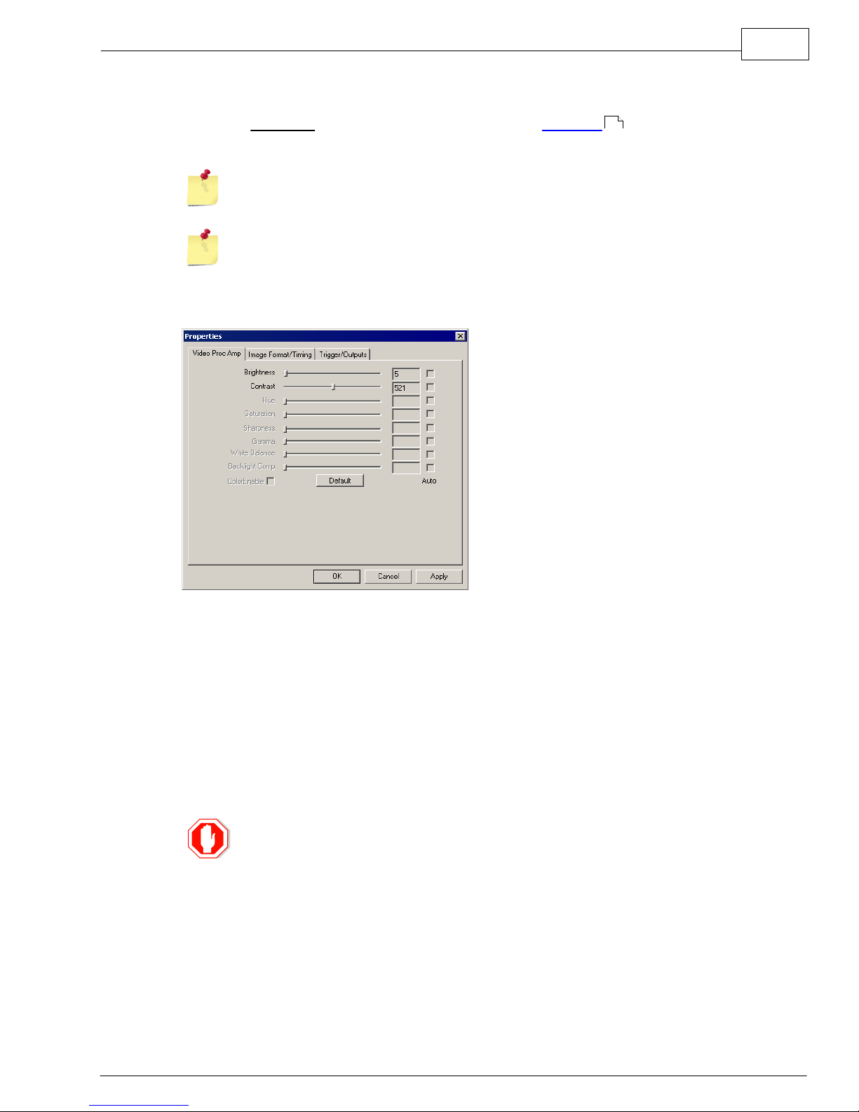
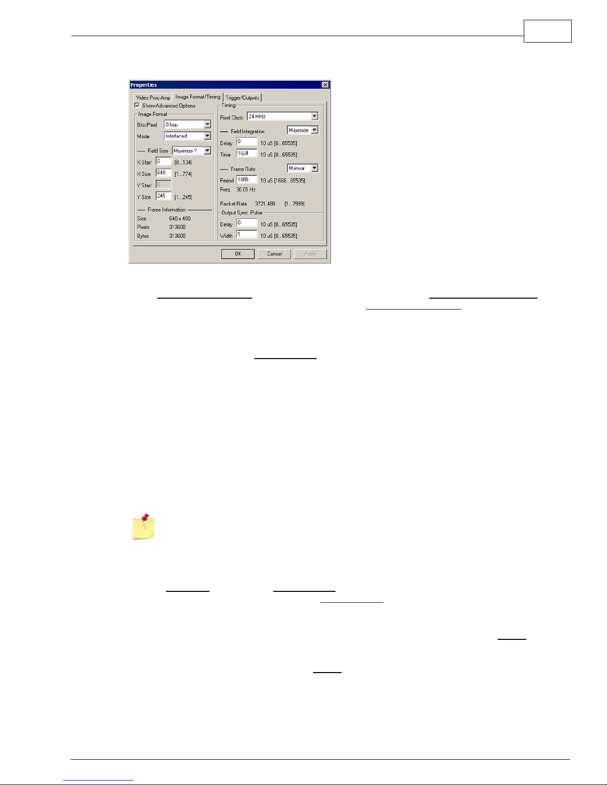
ION Optix MyoCam-S User manual

Hardware Manual
MyoCam-S

All rights reserved. No parts of this work may be reproduced in any form or by any means - graphic, electronic, or
mechanical, including photocopying, recording, taping, or information storage and retrieval systems - without the
written permission of the publisher.
Products that are referred to in this document may be either trademarks and/or registered trademarks of the
respective owners. The publisher and the author make no claim to these trademarks.
While every precaution has been taken in the preparation of this document, the publisher and the author assume no
responsibility for errors or omissions, or for damages resulting from the use of information contained in this document
or from the use of programs and source code that may accompany it. In no event shall the publisher and the author be
liable for any loss of profit or any other commercial damage caused or alleged to have been caused directly or
indirectly by this document.
Document date: July 14, 2008
Printed: July 2008 in Milton, MA USA
MyoCam-S Hardware Manual
Copyright 2008 IonOptix, LLC
IonOptix, LLC
309 Hillside St
Milton, MA 02186
phone: 617-696-7335
web: www.ionoptix.com

Table of Contents i
MyoCam-S Hardware Manual
1Introduction 1
2Connections 2
3Required Programs 3
4Camera Properties 4
5Driver Installation 10
6Technical Specifications 13
Index 14

Introduction:
1
MyoCam-S Hardware Manual
1Introduction
MyoCam-S Camera
MyoCam-S Power Supply
The MyoCam-S™ is an all-digital, variable frame rate camera that utilizes the USB 2.0 standard to
remove the restrictions of analog video formats and frame grabbers. Its maximum pixel clock rate has
been increased 70% above the original video-based MyoCam so that our “standard” ¼ height frame rate
jumped from 240Hz to 380Hz; sufficient to capture/characterize the fastest cardiac myocyte contractile
transient. The MyoCam-S gives you complete control over all aspects of video acquisition to deliver the
optimum combination of temporal and spatial resolution needed for your experimental requirements. All
analog processing and digitization is done inside the camera to minimize image noise. The digital data
are then transferred to the computer using a standard high-speed USB 2.0 port, eliminating the cost of a
frame grabber.
Features
• CCD sensor: 774 pixels wide by 245 lines (progressive) or 490 lines (interlaced)
• Variable frame rates (lines): 97Hz (245 lines), 250Hz (87 lines), 500Hz (36 lines), 1000Hz (10 lines)
• Complete control of camera acquisition window (start pixel & width and height)
• Selectable pixel clocks: standard, 2x high-speed, and low-noise
• 12-bit A/D converter with 8-bit or 12 bit readout
• Programmable CCD image gain and offset
• Programmable integration time to capture fast movement or increase camera sensitivity
• Programmable frame interval and external trigger to synchronize with other recording devices
• Synchronization of multiple cameras
• Compatible driver for use with any standard Windows video application
• Single cable to camera Power Supply
Manual Convention
The following conventions are used in IonOptix manuals:
·Underlined text refers to the names of interface elements shown in the illustrations included in most
sections.
·Italicized text refers to names given to specific parts of the IonWizard interface. These names can be
either IonOptix names, for example trace bar or names of Windows controls, like scroll bar and are
described in various sections of the manual.
·Bold text refers to mouse buttons or keystrokes that must be used in order to operate some function.
·The symbol § indicates the following name is a section in the manual.
A note icon indicates an important point that you should know.
An idea icon shows some ideas on how you can use a device or function.
A stop icon indicates a potential for personal injury, equipment damage or data
loss.

Connections:
MyoCam-S Hardware Manual
2
2Connections
Three electrical connections and one optical connection are required to operate the MyoCam-S: AC to the
Power Supply, Power Supply to the camera, camera to the computer and and camera to the optical image
source. There are also optional Auxiliary input and outputs and Synchronization connections.
Power
The AC power entry and associated fuse holder are accessible on the
back panel of the MyoCam-S power supply. It is a NEMA standard
power entry that can be used with any compatible power cord.
Note - The Power Supply will automatically adjust to any main voltage
between 100 and 240 volts AC.
Power entry
Camera Connections
The following connections are made to the camera:
1. The "CONTROLLER" plug connects to the the Power Supply using the
supplied DVI-I dual-link cable.
2. The "USB2" plug connects to the computer using a standard USB 2.0
cable.
3. A standard c-mount microscope adapter connects the camera to the
microscope.
Camera connections
Auxiliary Connections
The following optional connections are available on the front of the
MyoCam-S Power Supply:
CLK OUT 50% duty cycle programmable TTL clock output for
providing a common time base to other devices.
The specific frequency of this clock is set in the
Trigger/Outputs Properties page of the Camera
Properties dialog.
Auxillary connections
REP OUT 1µs positive-going TTL pulse that indicates start of each image frame.
PRE OUT Programmable duration, positive-going TTL pulse that occurs a
programmable time after the the start of image acquisition. The width and
delay are set in the Output Sync Pulse section of the Image Format/Timing
Properties - Advanced tab of the Camera Properties dialog.
TRIG IN (FUTURE USE - CURRENTLY DISABLED)
TTL Input that synchronizes start of image frame acquisition to the rising
edge of the input signal. The trigger input must be enabled in the Trigger
section of the Image Format/Timing Properties - Advanced tab of the
Camera Properties dialog.
Sync Connections
To synchronize multiple MyoCam-S cameras in a master/slave relationship,
you need to connect the Sync Out (located on the rear of the Power
Supply) for the "Master" camera to the Sync In (located on the rear of the
Power Supply) for the slave camera. In addition to making the physical
connections, you must enter the correct settings in the Trigger/Outputs
Properties page of the Camera Properties dialog.
Sync In&Out
8
4
6 4
6
4
8 4

Required Programs:
3
MyoCam-S Hardware Manual
3 Required Programs
The MyoCam-S is compatible with any Windows program that uses the Microsoft's DirectX 9 camera API
(DirectShow). As there are many available video acquisition programs, including Microsoft's free
MovieMaker, IonOptix does not provide a separate video display and acquisition program with the
MyoCam-S.
Displaying Live Video
My Computer - MyoCam-S
My Computer - Live Display
Windows XP provides a simple built-in mechanism for viewing live images from a DirectX camera in
the Windows Explorer. Simply double click on the the camera name (Aemics VI80U/USB Camera)
and then a live video display will appear.
Camera properties can not be changed from the Windows Explorer. The live display will
use the last parameters set by a program that provides access the MyoCam-S camera
properties, such as MovieMaker.
Accessing Camera Properties in Microsoft MovieMaker
All of the MyoCam-S video settings are set in software
using the standard Windows DirectShow camera
properties function. The location and instructions for
accessing the camera properties vary depending upon
the program that you are using. However, once they are
open, they generally operate the same way.
For example, if you are using Windows Movie Maker,
you access the MyoCam-S properties pages by clicking
on the "Capture from video devices" link. Then, select
"Aemics VIO80U USB Camera", click the "Configure..."
button (1) and finally click the "Camera Settings" button
(2). The MyoCam-S Properties dialog will appear,
allowing you to adjust the settings.
Windows Moviemaker Camera Properties
4

Camera Properties:
MyoCam-S Hardware Manual
4
4 Camera Properties
The MyoCam-s Properties dialog is accessible through several programs . The dialog is divided into
three separate tabs which control different aspects of the camera.
Camera property settings that are changed using the standard property pages documented
below are automatically stored in the registry and become the starting values for any other
program that uses the MyoCam-S.
IonWizard does not use the standard camera properties pages and does not use or change
the values in the registry. Please refer to the IonWizard documentation for more details on
how it operates with the MyoCam-S.
Video Brightness/Contrast
Video Properties
The "Video Proc Amp" page is used to control normal video parameters.
Brightness Controls the level that is digitized as black. Decreasing the black level
makes the entire image darker. If the black level is too low many dark areas
will be solid black, if its too high "black" areas will appear gray.
Contrast Controls the overall intensity of the video image. If the contrast is too high
bright areas will "wash out" to solid white. If too low the bright areas of the
image will be gray.
Default Sets brightness and contrast to default values. NOTE - do NOT use this
function as the values that it sets are not the correct 'default values'.
The correct default values are Brightness=10 and Contrast=500.
If Brightness and Contrast are set incorrectly it will be hard, if not impossible, to
see the video image. To set to reasonable default values, set Brightness to 10 and
Contrast to 500.
3

Camera Properties:
5
MyoCam-S Hardware Manual
Image Format/Timing Properties - Basic
Basic Image Format/Timing Properties
When Image Format/Timing is selected as the current property AND the Show Advanced Options
check box is NOT CHECKED, the basic version of the image Image Format/Timing controls (shown
above) will be displayed. In basic mode, you enter the desired frame rate and the system will set the
maximum number of lines (y size) and integration time that the camera will support at the given rate.
Values entered in the advanced version of the Format/Timing properties are used in basic
mode. Check Show Advanced Options to see the current values for these 'extra'
parameters.
Frame Information
The Frame Information group displays information about the image. This information is based on
values that can be entered when Show Advanced Options is checked.
Size Number of pixels and number of lines in each image (frame) acquired
Pixels Total number of pixels in each image
Bytes Total number of bytes in each image
Frame Rate
Period Enter the number 10µs clock periods per frame (i.e. frame period in
milliseconds times 100).
Freq. Displays the resulting frame frequency for the entered Period given the
current mode (set when Show Advanced Options is checked).
Packet Rate Displays the USB packet rate. This information is useful for debugging
purposes.
Here are some sample values for Period with resulting Frequencies for progressive mode:
3333=30Hz 1666=60Hz, 1000=100Hz, 500=200Hz, 100=1kHz

Camera Properties:
MyoCam-S Hardware Manual
6
Image Format/Timing Properties - Advanced
Advanced Image Format/Timing Properties
When Image Format/Timing is selected as the current property AND Show Advanced Options check
box IS CHECKED, the advanced version of the image Image Format/Timing controls (shown above)
will be displayed. The advanced controls give you control of all software-adjustable MyoCam-S
parameters.
Image Format
The main controls in the Image Format group determine the major characteristics of the image
that will be acquired:
Bits/Pixel Select number of bits to store for each pixel
8 bpp - 8 bits/pixel, smallest pixel size, needed to achieve maximum
frame-rates and smallest images
12 bpp - 12 bits/pixel, more detail for slower frame-rates, doubles size of
resulting images
Mode Selects camera acquisition mode
Progressive - Only even lines of the CCD are acquired which doubles
the available frame rate and halves the number of lines per frame.
Interlaced - Each image is acquired in two halves, even lines then odd
lines, and then combined into a single image. This results in all
lines being acquired but a decrease in the maximum frame-rate.
When acquiring interlaced images, the odd and even lines are acquired at different points
in time which can result in "comb" effects if the image moves between odd and even
frames. This may make interlaced mode inappropriate in some situations.
Image Format - Field Size
The Field Size section of the Image Format group allows you to specify the dimensions of the
image given the constraints of the main Image Format options entered above:
drop down Control how field size parameters are adjusted when values in OTHER
controls are changed:
Maximize Y - As values are changed in other areas, the Y Size value will
be recalculated to the maximum possible value given other
parameters.
Manual - The Y Size value will not be changed which may limit the
maximum values of other parameters.
X Start First pixel to acquire in line. To center the acquired image on the sensor
chip, enter half of maximum value.

Camera Properties:
7
MyoCam-S Hardware Manual
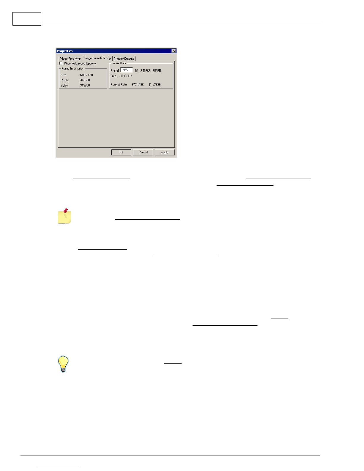
X Size Number of pixels to acquire in a line. The primary reason to decrease X
Size is to reduce the size of the resulting image files which is only
significant if the images are saved.
Y Start Starting line to acquire. The value is fixed at zero for the MyoCam-S.
Y Size Total number of lines to acquire. The maximum value automatically
accounts for Mode selection in Image Format group as well as
requested Frame Rate if Frame Rate is set to "Manual".
Decreasing Y Size will result higher maximum frame rates while changes in X Size do not
have a significant effect in the maximum frame rate.
Image Format - Frame Information
The Frame Information section of the Image Format group displays information about the
resulting image given the values that you have selected.
Size Number of pixels and number of lines in each image (frame) acquired
Pixels Total number of pixels in each image
Bytes Total number of bytes in each image
Timing
The main controls in the Timing group allows you to select the clock used to read the image data
from the CCD sensor.
Pixel Clock Selects the CCD pixel (read-out) clock frequency:
24 MHz - high speed clock which results in the maximum frame rate for
a given y-size.
12 MHz - medium speed clock decreases CCD read-out noise, which
increases image quality, while decreasing the maximum frame rate
for a given y-size by 1/2.
1 MHz - low seed clock provides lowest CCD read-out noise to allow for
the maximum image quality when acquiring images with long
integration times This option dramatically reduces the maximum
frame-rate.
The qualitative difference between read-out clocks may not be noticeable and/or
measurable unless you are in a low light (high gain) situation.
Timing - Field Integration
The Field Integration section of the Timing group allows precise control over when the CCD is
sensitive to light.
drop down Control how field size parameters are adjusted when values in OTHER
controls are changed:
Maximize - As values are changed in other areas, the Time field will be
recalculated to the maximum possible value given other
parameters.
Manual - The Time field value will not be changed which may limit the
maximum values of other parameters.
Delay Number of 10µs clock periods to delay from frame "start" before
"exposing" CCD.
Time Number of 10µs clock periods to "expose" CCD.
Changing the Field Integration Time (either manually or via Maximize) effects the
brightness of the acquired image in the same way that changing the shutter speed does on
a 35mm camera.

Camera Properties:
MyoCam-S Hardware Manual
8
If you set the Field Integration Time to a fixed value (drop down=manual), the overall
brightness of the image will not change as you pick different frame-rates.
If you have enough light, a shorter Field Integration Time can be used to decrease the
amount of motion blur caused by the image moving while the CCD is exposed. Again, this
is similar to using fast shutter settings on a 35mm camera.
Timing - Frame Rate
The Frame Rate section of the Timing group allows you to specify specific camera frame rates.
Period Enter the number of 10µs clock periods per frame (i.e. frame period in
milliseconds times 100).
Freq. Displays the resulting frame frequency for the entered Period.
Packet Rate Displays the USB packet rate. This information is useful for debugging
purposes.
Here are some sample values for Period with resulting frequencies for progressive mode:
3333=30Hz 1666=60Hz, 1000=100Hz, 500=200Hz, 100=1kHz
Output Sync Pulse
The Output Sync Pulse group allows control of the timing of the TTL output pulse that is output
on the PRE OUT BNC on the front panel of the Power Supply . The output sync pulse
occurs for every frame acquired.
Delay Number of 10µs clock periods from frame "start" to setting output pulse
to active.
Width Number of 10µs clock periods before pulse is set to inactive. Set to zero
to disable.
Delay happens BEFORE the CCD is sampled and increases the amount of time required to
sample each frame which decreases the maximum frame-rate
Here are some sample values for Delay/Width and the resulting delays:
1=10µs, 25=250µs, 100=1ms, 500=5ms, 1000=10ms
Trigger/Outputs Properties
MyoCam-S Trigger/Output Properties
When Trigger/Outputs tab is selected, the following controls will be displayed:
2 1

Camera Properties:
9
MyoCam-S Hardware Manual
Triggering
The Triggering group allows you to configure multiple MyoCam-S cameras to operate in a
master/slave relationship so that images acquired between the two cameras are phase-locked.
Master Camera generates all timing and clocks required for operation.
Ext. Trigger - If selected the MyoCam-S outputs signals needed to
provide timing and clock signals to a 2nd, slave, MyoCam-S
Slave Camera uses timing and clock signals from first, master, MyoCam-S.
Master/Slave and Ext Trigger options do not currently work, Contact IonOptix for
more information.
General Purpose Clock
The General Purpose Clock group allows a synchronization clock signal to be output on the CLK
OUT BNC on the front panel of the Power Supply .
Counter Divisor value from the 24MHz crystal
Rate Resulting output clock frequency for the entered Counter value
Version Information
Firmware MyoCam-S firmware version
FPGA MyoCam-S programmable logic code version
Board MyoCam-S board version
Camera ID Unique camera ID value
Debug Output
Dumps a raw image for debugging purposes.
2 1

Driver Installation:
MyoCam-S Hardware Manual
10
5Driver Installation
The MyoCam-S drivers are distributed as a zip file named "MyoCam-S ddmmmyy.zip" where ddmmmyy is
the day, month and year the driver was released as in "03jul08". Contact IonOptix for instructions on
receiving the latest version of the MyoCam-S driver file.
Once you have the MyoCam-S driver zip file you will need to unzip the driver files to your computer then
select them in the Add Hardware Wizard that runs when the MyoCam-S is attached for the first time.
Copy and unzip driver files
The first step in installing the MyoCam-S drivers is to copy them onto your computer.
Copy the MyoCam-S driver zip file to any directory on your
computer's hard drive. For this example we will copy it to
the file "MyoCam-S 03jul08.zip" to "C:\temp"
Using Windows explorer (My Computer), locate the file that
you just copied and extract the zip file contents by right
clicking on the zip file and picking "Extract All..."
Click "Next >" to skip the opening screen (not shown).
On the select destination page, edit the directory name so
that the name of the base file is no longer included (i.e., If
you are extracting "MyoCamS-03jul08.zip" in the "C:\Temp"
directory, the default value destination will be
"C:\Temp\MyoCamS-03jul08". Delete the
"MyoCamS-03jul08" so that it reads "C:\Temp".). Then, click
"Next >".
On the extraction completed page, uncheck "Show
Extracted Files" then click "Finish" to complete extracting
the zip file contents.
When you are done, you should see the zip file and a
normal directory named "MyoCamS".
Attach MyoCam-S and Select Drivers
After the driver files have been copied and unzipped to your computer, you can attach the
MyoCam-S USB connection and turn on the power. When Windows sees the new USB device, it
will automatically start the "Found New Hardware" process and let you select the driver.

Driver Installation:
11
MyoCam-S Hardware Manual
The MyoCam-S actually has two drivers. The first is a "loader" that is responsible for initializing the
loading the MyoCam-S program into the camera and the second is the MyoCam-S driver itself. The
loader is found first, immediately followed by the camera driver.
Windows displays the following bubble in the system
tray when it detects new hardware.
Select “no” you don’t want to search windows
update and click “Next >".
Select “Install from a list or specific location
(Adanced)” and click "Next >".
- Select “search for the best…”,
- uncheck “search removable media…”,
- check “include this location…”
- enter or browse to the MyoCamS directory that you
unzipped in the steps above (in our example,
c:\temp\MyoCamS).
Click "Next >".

Driver Installation:
MyoCam-S Hardware Manual
12
Windows will start to install the driver then display
this warning. Click “Continue Anyway”.
When completed, you will see this message. Click
"Finish".
Immediately after you click “Finish”, a second “Found New Hardware” popup will be displayed and
the "Found New Hardware Wizard" will start again to load the driver for the camera itself. Repeat the
process above to load the camera driver.

Technical Specifications:
13
MyoCam-S Hardware Manual
6Technical Specifications
Here are the specifications for the various parts of the MyoCam-S
Power Supply
Input Power 100-240VAC, 50-60Hz, 1.5A fuse
Power Entry NEMA standard for removable power cord
Auxiliary In/Out Phase-locked programmable output clock, Frame start and programmable
frame delay output pulses, Trigger input
Synchronization Frame-level synchronization between master/slave cameras using Sync In/
Sync Out
Camera connector Female DVI-I dual-link connector
Camera
CCD Sensor 774 pixels wide by 245 lines (progressive) or 490 lines (interlaced)
USB connector USB "B" connector
Power supply conn. Female DVI-I dual-link connector
Acquisition Options
Sampling modes Progressive or Interlaced
Sample resolution 12-bit A/D converter with 8-bit or 12-bit readout
Integration time Programmable, 10us - 0.6s
Pixel clock High-speed (24Mhz), medium (12Mhz) and low-noise (1MHz)
Frame Rates (8-bit) 97Hz (245 lines), 250Hz (87 lines), 500Hz (36 lines), 1000Hz (10 lines)
Gain/offset Programmable, analog
Software Compatibility
General Windows DirectShow compatible drivers
Supported versions Windows XP, Windows 32-Bit Vista only
Cables (supplied)
Camera to Power sup Six foot DVI-D dual-link cable
USB Six foot USB 2.0 cable
Power Cord Six foot NEMA to U.S. or European plug

Index
MyoCam-S Hardware Manual
14
Index
Accessing MyoCam-S properties 3
Connections
Auxilliary 2
Camera 2
Power 2
Sync 2
Driver
Obtaining 10
Unpacking 10
Drivers
Installation 10
Selecting 10
Features 1
Image Format/Timing Properties
Advanced 6
Basic 5
Manual Conventions 1
Microsoft MovieMaker
Accessing MyoCam-S properties 3
Technical Specifications 13
Trigger/Output Properties 8
Video Brightness/Contrast Properties 4
Windows XP
Displaying Live Video 3
Table of contents