1.1.2 IO-Flasher PRO– STM8
IO-FLASHER PRO is the advance version of IO-FLASHER having LCD DISPLAY. It has all the
features of IO-FLASHER – STM8 with below features in addition.
Features of IO-Flasher PRO - STM8
Standard Programming Connector: -
Standard 4-Pin SWIM
connector compatible with STMicroelectronics STM8 Eval board
programming connectors.
Offline Mode: -
Stand-alone SWIM programmer (Once set up,
Flasher can be controlled without the use of PC program).
Programming starts with simply button press.
Online Mode: -
Programming can be done directly from IO-
FLASHER GUI.
Limit Counter: - Limit counter can set to stop offline
programming after counter reached.
Serial Number Programming: - Any serial number can be
programmed to target MCU with automatic incrementing.
Password protection: - You can protect you programmer with
a password to protect it from erase or rewriting. This will also
prevent the Limit counter status.
LCD Display: - IO-Flasher PRO– STM8 has interactive OLED LCD Display
Program Menu: - It stores all project settings from GUI to work independently without GUI.
This Menu shows all settings done from GUI.
Interactive programming: - LCD display Programming status, Number of chips
programmed. Error codes and meaning on that error code.
Dual Mode: - While IO-FLASHER is configured as offline mode. Its can be still used in
online mode for same or different firmware code.
Programmable Power Output: - No power supply required, Powered through USB. Target
board can be power from IO-FLATHER. Output voltage can be adjusted from 0 Volt to
~5Volt depending on selected target device (up to 200mA to target with overload
protection).
Target Power Sensing: - If target is self-powered or powered from IO-FLASHER, then it
can be measured by the IO-FLASHER.
In-built Protection: - All external port protected with ESD, Short circuit and over current.
Isolation is available in Isolated version of IO-FLASHER (e.g. IO-FLASHER -STM8/ISOL)
Programming Options: - Have many programming options to program Flash, EEPROM,
Option memory with auto lock feature.
Supported devices: - Support for all STM8 devices
STM8S, STM8L, STM8AF, STM8AL
IO-FLASHER GUI: - Highly professional GUI with simple and user-friendly interface.
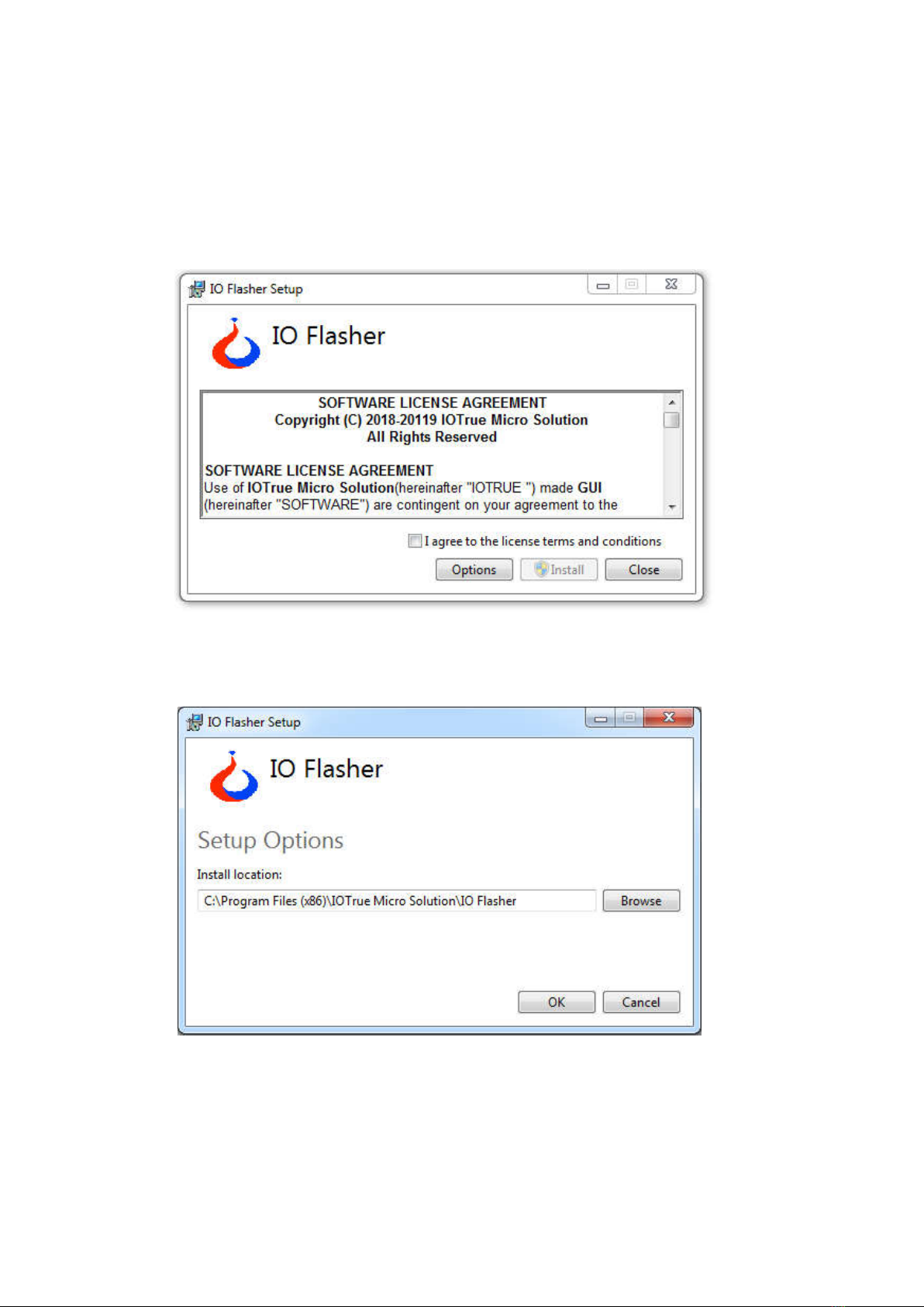
Figure 2