iQe CP318 User manual

CP318
INSTALLATION INSTRUCTIONS
The CP318 combined wireless room stat and timeswitch allows a
combi boiler system to have a room thermostat added without the
need for any additional wiring.
Replacing the existing timeswitch with the CP318 will allow the
room thermostat to be connected wirelessly producing immediate
energy savings in houses where no previous room thermostat
has been fitted.
The device is intended to upgrade existing combi boiler systems
that do not have an existing room thermostat. It is not intended for
new installations where it will be necessary to install two heating
zones in order to comply with current Building Regulations.
Combined Time Control and Room Thermostat
1

Installation and connection should only be carried out by a
suitably qualified person and in accordance with the current
edition of the IEE wiring regulations.
WARNING: Isolate mains supply before commencing installation.
An example circuit diagram for a typical combi boiler installation is
shown below. This diagram is schematic and should be used for
guidance only.
For the installer
2
CP318 Timeswitch

Fitting the backplate
Once the backplate has
been removed from the
p a c k a g i n g p l e a s e
ensure the timeswitch is
re-sealed to prevent
damage from dust and
debris.
The backplate should
be fitted with the wiring
terminals located at the top and in a position that allows a total
clearance at last 50mm around the unit.
Direct wall mounting
Offer the backplate to the wall in the position where the
timeswitch is to be mounted, remembering that the backplate fits
to the left hand end of the control. Mark the fixing positions
through the slots on the backplate (fixing centres of 60.3mm), drill
and plug the wall, then secure the backplate in position. The slots
in the backplate will compensate for any misalignments of the
fixings.
Wiring box mounting
The backplate may be fitted directly onto a single gang steel flush
wiring box complying with BS4662, using two M3.5 screws. The
CP318 is suitable for mounting on a flat surface only; they must
not be positioned on a surface mounted wall box or on unearthed
metal surfaces.
N L 1 2 3 4
100mm
50mm
50mm
50mm
3

Electrical connections
All necessary electrical connections should now be made. Flush
wiring can enter from the rear through the aperture in the
backplate. Surface wiring can only enter from beneath the
timeswitch and must be securely clamped. The mains supply
terminals are intended to be connected to the supply by means of
fixed wiring. Recommended cable sizes are 1.00 or 1.5mm2
The CP318 is double insulated and does not require an earth
connection but an earth connection is provided on the backplate
for terminating cable earth connectors. Earth continuity must be
maintained and all bare earth connectors must be sleeved.
Ensure no earth conductors are left protruding outside the central
space enclosed by the backplate.
Internal diagram - CP318 Timeswitch
The CP318 has voltage
free contacts.
A link L - 2 is required
for mains voltage
applications
NL1234
230V 50Hz OFF ON
COMM
1
2
3
4
+
PULL TO REMOVE
Rear view of timeswitch
1. RATINGS LABEL
2. BATTERY
3. CONNECTOR PINS
4. PRODUCTION DATE LABEL
4

Battery reserve
The battery must be commissioned prior to fitting the timeswitch
to the backplate. This is achieved by the means of a
commissioning strip situated in the back of the unit. Pull out the
battery commissioning strip at the back of the timeswitch and re
insert the battery; the reserve is now activated. When the
timeswitch is running the battery reserve clock display will
disappear. This is to prolong the life of the battery.
Fitting the timeswitch
If surface wiring has been used, remove the knockout/insert from
the bottom of the timeswitch to accommodate it.
Loosen the two ‘captive’ retaining screws
on the bottom of the backplate. Now fit
the timeswitch to the backplate, ensuring
the lugs on the backplate engage with the
switch.
Swing the bottom of the timeswitch into
position ensuring that the connection
pins on the back of the unit locate into the
terminal slots in the backplate.
Tighten the two captive retaining screws
to fix the unit securely.
Then switch on the mains supply.
On completion of the installation please reset the timeswitch as
detailed next;
End view of CP318
timer
5

Resetting the timeswitch
On the CP318 press the SET and SELECT buttons together.
Then release the buttons and the timeswitch will return to
preset factory settings.
The preset factory settings are
illustrated on page 12 of the
USER GUIDE.
The unit is now ready to be signed on to its room thermostat,
to suit the user’s requirements
General Information
BATTERY
The timeswitch is fitted with a non-rechargeable, long life battery,
which will maintain the programmed time settings for a minimum
of ten months with the supply disconnected.
THIS SHOULD BE SUFFICIENT TO COVER POWER
INTERRUPTIONS DURING THE LIFE OF THE UNIT.
During power interruptions the display will be blank, after 3 days
the current time of day will be lost. These measures are to prolong
the battery life.
SERVICE AND REPAIR
This timeswitch is NOT user serviceable. Please do not
dismantle the unit. In the unlikely event of a fault developing
please refer to the RESETTING THE timeswitch section of this
user guide shown above. If this fails to resolve the problem
please contact your installer, a local heating engineer or a
qualified electrician.
SET
SELECT
6

Room Thermostat
Installation and pairing instructions
The wireless electronic battery powered
room thermostat uses interoperable two-
way RF mesh networking technology to
provide optimum comfort with close control
of the energy used to heat the home
without the need for additional wiring or
unsightly cable runs.
The thermostat will only operate when 2 x AAA batteries have
been fitted and the thermostat is installed and communicating
with the timer/receiver unit.
INSTALLATION AND CONNECTION SHOULD ONLY BE
CARRIED OUT BY A SUITABLY QUALIFIED PERSON.
Instructions for pairing the room thermostat with the
timeswitch
These devices use the latest Z-Wave wireless communication
technology to give a reliable wireless link that should not suffer
from interference from other nearby devices. The device
comprises a thermostat and its receiver. Pairing the devices on
site ensures reliable communication.
Follow these steps to ensure that the thermostat will
communicate satisfactorily with its receiver. This is best carried
out with the thermostat held nearby the (powered) timeswitch.
7

Stage 1
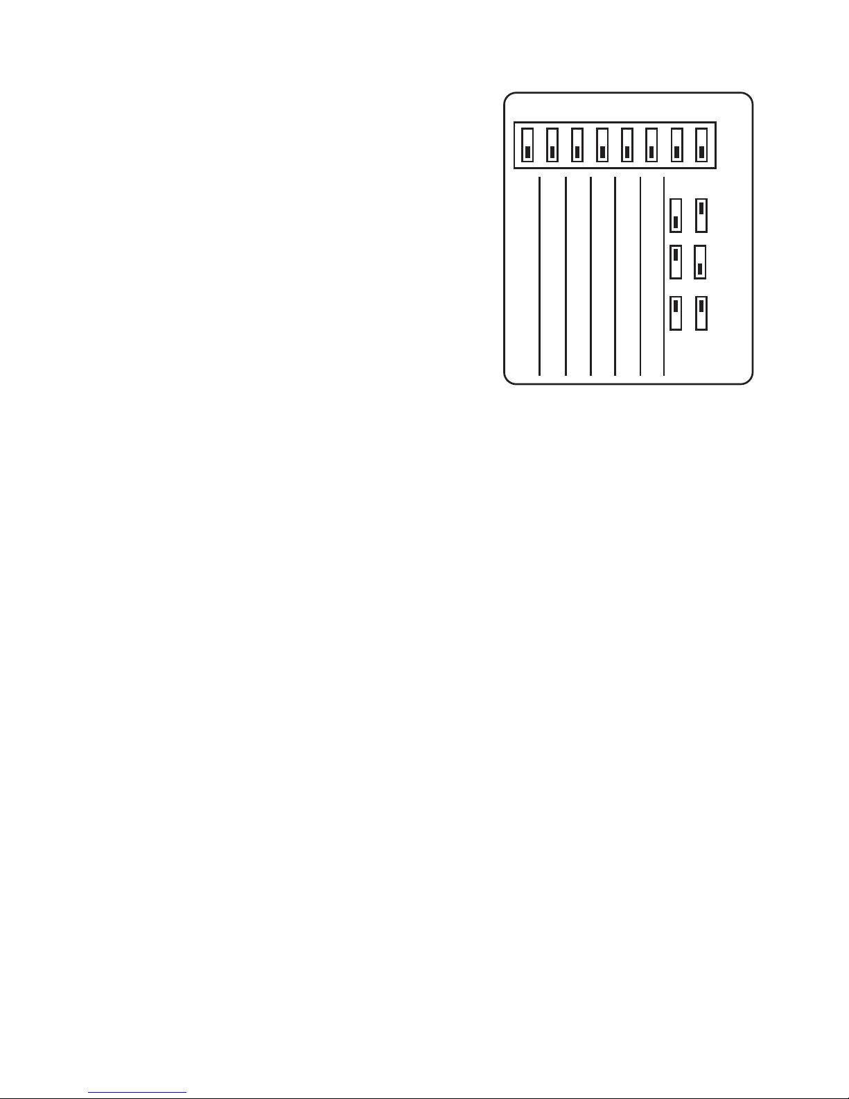
1) Set the number 1 DIL switch on the
back of the thermostat to the On (Up)
position and the display will change to
show the letter ‘I’. If the letter ‘L’ appears,
carry out stage 1A opposite.
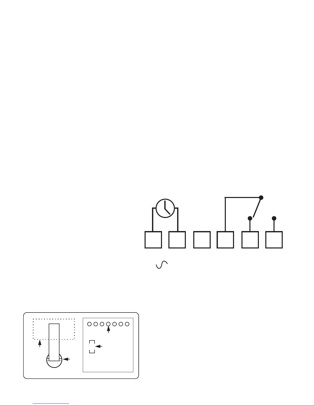
2) Power up the CP318 timeswitch.
3) Press the dial on the front of the
thermostat once so that the ‘I’ in the
display flashes.
4) Press and hold the ‘Boost’ and
‘Enter’ buttons on the front of the
Timeswitch until an indicator appears
in its display against the radio aerial
symbol.
5) After a few seconds the radio mast
symbol will appear in the display along with the letters IP.
6) Reset the number 1 DIL switch on the back of the
thermostat to the Off position and the temperature will appear
in the display.
7) Now check the CP318 time control is receiving signals
from the thermostat by turning the time switch to an ‘On’
setting with the red indicator light lit and turning the
thermostat up and down to make the boiler switch on and off.
N.B. There is a half second delay in switching On and Off on
receipt of the commands. There is no ‘click’ from the
thermostat which is silent in operation but there will be an
audible ‘click’ from the CP318 when it is ‘On’ and the
thermostat switches On and Off.
8) When the thermostat is calling for heat a flame symbol will
appear in its display.
9) Z Wave communication is now successfully established.
ON
OFF
1 INSTALLER MODE
2 NOT USED
3 NOT USED
4 NOT USED
5 NOT USED
6 NOT USED
TPI
3
TPI
6
TPI
12
SWITCH CONFIGURATION CP318
7
8
Switch positions for
different TPI settings.
Press and hold ‘BOOST’ and
‘ENTER’ buttons to ‘SIGN ON’
or ‘PAIR’ the thermostat
8

Stage 1A – Only used if ‘L’ is displayed instead of ‘I’
1) Turn the dial of the thermostat until the letter P appears in
the display.
2) Press the dial twice and PP should appear in the display.
3) Turn the dial until the letter ‘I’ appears in the display and
return to the main instruction.
Under normal circumstances the thermostat and
timeswitch will be ‘paired’ easily by following the
procedure shown under Stage 1 of the pairing
instructions
Only use Stage 2 if a radio link cannot be successfully
established between the two devices.
Stage 2 – Only used if the above procedure does not
establish a successful communication link
1) Turn the dial of the thermostat until the letter P appears in
the display.
2) Press the dial twice and PP
should appear in the display.
3) Now turn the dial until letter E
appears in the display.
4) Press the dial once and the
display should flash ‘E’.
5) Press and hold the ‘Boost’
and ‘Enter’ buttons on the
timeswitch.
6) Turn the thermostat dial until
‘I’ appears in the display and
return to the main instruction.
Press and hold ‘BOOST’ and
‘ENTER’ buttons to ‘SIGN ON’
or ‘PAIR’ the thermostat
9

DIL switch settings – TPI temperature control software
Thermostats using TPI (Time
Proportional Integral) control
algorithms will reduce the
temperature swing that normally
occurs when using traditional
bellows or thermally operated
thermostats. As a consequence, a
TPI regulating thermostat will
maintain the comfort level far more
efficiently than any traditional
thermostat.
When used with a condensing boiler, the TPI thermostat will help
to save energy as the control algorithm allows the boiler to
operate in condensing mode more consistently compared to older
types of thermostat.
• DIL switch numbers 7 and 8 should be set as diagram
opposite.
• For Gas boilers set the TPI setting to 6 cycles per hour.
(Default setting)
• For Oil boilers set the TPI setting to 3 cycles per hour.
• For Electric heating set the TPI setting to 12 cycles per hour.
ON
OFF
1 INSTALLER MODE
2 NOT USED
3 NOT USED
4 NOT USED
5 NOT USED
6 NOT USED
TPI
3
TPI
6
TPI
12
SWITCH CONFIGURATION CP318
7
8
Switch positions for
different TPI settings.
10

Fitting the Room Thermostat
Before final installation it is advisable to commission the product
and ensure that the Thermostat and Receiver are
communicating satisfactorily. First install the 2 type AAA batteries
provided making sure that they are fitted correctly as indicated by
the markings in the battery compartment.
Once the thermostat and
receiver are successfully
‘paired’ the thermostat can
be installed in its correct
location. Please see Z-
Wave pairing instructions
on page 8.
Avoid installing the thermostat against or behind any large metal
surfaces which could interfere with the radio signals to and from
the CP318 timer with combined receiver. The thermostat should
be mounted on an internal wall approximately 1.5 metres from
floor level using the wall plate provided and should be in a
position away from draughts, direct heat and sunlight. Ensure
that there will be enough pace to allow easy access to the two
retaining screws located at the base of the wall plate.
11

Before fixing the wall plate in position check to see that the
thermostat and boiler are still able to communicate satisfactorily
by turning the thermostat temperature up and down to switch the
boiler on and off.
Offer the plate to the wall in the position where the thermostat is to
be mounted and mark the fixing positions through the slots in the
wall plate. Drill and plug the wall, then secure the plate into
position. The slots in the wall plate will compensate for any
misalignment of the fixings.
Complete the installation by swinging the room thermostat into
position by engaging with the lugs at the top of the wall plate
before pushing it carefully home
into its plugin terminal block.
Tighten the 2 captive screws on
the underside of the unit.
Now ensure that the heating
system is responding to the
ON/OFF commands from the
Room Thermostat and explain its
operation to the householder
before handing over the User
Instructions.
12

13
Timeswitch specification
Contact Rating 3 (1) Amps 230V AC
Contact Type Micro-disconnection
changeover
Voltage free
Supply 230V AC 50Hz only
Pollution Degree 2
Class A Software Type 1 Control
Operating Temperature Range 0°C to +40°C
Battery Life 10 months continuous
operation (minimum)
Case Material Thermoplastic, flame retardant
Dimensions 84mm x 150mm x 29mm
Display Back lit liquid crystal
Clock 12 hour AM/PM
Auto BST/GMT changeover
Displayed Time adjustments 1 minute steps
Switched Time adjustments 10 minute steps
Operating periods per day 3 per day(Separate
programmes possible for each
day of the week)
Override 1 hour boost, 1 hour extension
to On period, instant advance
Mounting Industry standard 6 terminal
plug in wall plate
Transmitter Frequency 868MHz
Design Standard EN60730-2-7 IP30
EN300-220 R &
TTE Directive EN301-489

Thermostat specification
Power supply 2 x AAA alkaline batteries
Temperature accuracy +/- 0.5°C
Transmitter frequency 868MHz
Dimensions 86mm x 86mm x36.25mm
Pollution control Degree2
Design standard EN60730 - 2-9
Temperature range 5°C – 30°C
Enclosure protection IP30
Operating temperature range 0-40°C
Case material Thermoplastic flame retardant
Leaflet number P85496 Issue 1
www.iQE.co.uk
Trade House BA22 8RT
14
Other manuals for CP318
1
Table of contents
Other iQe Thermostat manuals
Popular Thermostat manuals by other brands

Mars
Mars 70812 Installation and operating instructions

TPS
TPS PTR5100-5500W instructions

AKO
AKO 226.0120 Series Mounting and Servicing Instructions

Buderus
Buderus ModuLink 250 RF installation instructions

Elnur Gabarron
Elnur Gabarron CTM20 Installation and use manual

Aube Technologies
Aube Technologies TH140-28 Installation and user guide