iRAYPLE L5082MG170E User manual

Line Scan Camera
User’s Manual
V1.0.0

I
Foreword
General
This manual introduces the functions and operations of the line scan camera (hereinafter referred to
as "the camera").
Model
L5082MG170E, L5082MK170E, L5022MG141E, L5022CG141E, L5042MG141E,
L5042CG141E, L5027MG140E, L5027CG140E, L5047MG140E, L5047CG140E
Safety Instructions
The following signal words might appear in the manual.
Signal Words
Meaning
DANGER
Indicates a high potential hazard which, if not avoided, will result in
death or serious injury.
WARNING
Indicates a medium or low potential hazard which, if not avoided,
could result in slight or moderate injury.
CAUTION
Indicates a potential risk which, if not avoided, could result in property
damage, data loss, reductions in performance, or unpredictable results.
TIPS Provides methods to help you solve a problem or save time.
NOTE Provides additional information as a supplement to the text.
Revision History
Version
Revision Content
Release Time
V1.0.0 First release. July 2021
Privacy Protection Notice
As the device user or data controller, you might collect the personal data of others such as their face,
fingerprints, and car plate number. You need to be in compliance with your local privacy protection
laws and regulations to protect the legitimate rights and interests of other people by implementing
measures which include but are not limited: Providing clear and visible identification to inform
people of the existence of the surveillance area and provide required contact information.
About the Manual
The contents of this manual are for reference only, and timely update cannot be guaranteed.
Slight differences might be found between the manual and the product. If you have any
questions, please contact the technical support of the corresponding area.
We are not liable for losses incurred due to operating the product in ways that are not in
compliance with the manual.
The manual will be updated according to the latest laws and regulations of related jurisdictions.
For detailed information, see the paper user’s manual, use our CD-ROM, scan the QR code or
visit our official website. The manual is for reference only. Slight differences might be found
between the electronic version and the paper version.

II
All designs and software are subject to change without prior written notice. Product updates
might result in some differences appearing between the actual product and the manual. Please
contact customer service for the latest program and supplementary documentation.
There might be errors in the print or deviations in the description of the functions, operations
and technical data. If there is any doubt or dispute, we reserve the right of final explanation.
Upgrade the reader software or try other mainstream reader software if the manual (in PDF
format) cannot be opened.
All trademarks, registered trademarks and company names in the manual are properties of their
respective owners.
Please visit our website, contact the supplier or customer service if any problems occur while
using the device.
If there is any uncertainty or controversy, we reserve the right of final explanation.

III
Important Safeguards and Warnings
This section describes the content covering proper handling of the device, hazard prevention, and
prevention of property damage. Read these contents carefully before using the device, comply with
them when using, and keep the manual well for future reference.
Operation Requirements
Transport, use and store the device under allowed humidity and temperature conditions.
Prevent liquids from splashing or dripping on the device. Make sure that there are no objects
filled with liquids on top to avoid liquids flowing into the device.
Do not disassemble the device.
Only use the device within the rated power range.
Make sure that the power supply of the device works properly before use.
Do not pull out the power cable of the device while it is powered on.
Installation Requirements
Observe all safety procedures and wear required protective equipment provided for your use
while working at height.
Do not expose the device to direct sunlight or heat source.
Do not install the device in humid, dusty or smoky places.
Install the device in a well-ventilated place, and do not block the ventilator of the device.
Strictly abide by local electrical safety standards, and make sure that the voltage in the area is
steady and conforms to power requirements of the device.
Use the power adapter or case power supply provided by the device manufacturer.
Connect the device with the adapter before power on.
Do not connect the device to more than one power supply. Otherwise, the device might be
damaged.
The power supply must conform to the requirements of ES1 in IEC 62368-1 standard and no
higher than PS2. Note that power supply requirements are subject to the device label.
Connect the class I electrical appliance to a power socket with protective earthing.

IV
Table of Contents
Foreword............................................................................................................................................................ I
Important Safeguards and Warnings............................................................................................................. III
1 Product Information...................................................................................................................................... 1
Product Overview ...................................................................................................................................................................... 11.1
Product Features ........................................................................................................................................................................ 21.2
1.2.1 CameraLink Line Scan Camera................................................................................................................................. 2
1.2.2 GigE Line Scan Camera............................................................................................................................................... 2
Typical Networking.................................................................................................................................................................... 21.3
Application Environment........................................................................................................................................................ 31.4
Status Indicator Lights ............................................................................................................................................................. 31.5
2 MV Viewer Installation and Camera Connection......................................................................................... 4
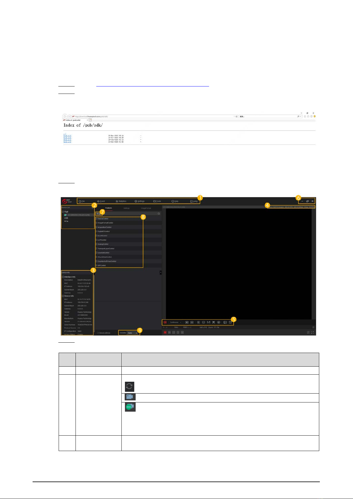
Downloading and Installing MV Viewer ............................................................................................................................ 42.1
Connecting Camera .................................................................................................................................................................. 42.2
3 Function Parameters ..................................................................................................................................... 7
Line Scan Rate ............................................................................................................................................................................. 73.1
3.1.1 Factors............................................................................................................................................................................... 7
3.1.2 Configuring Line Scan Rate....................................................................................................................................... 7
Frame Timeout ............................................................................................................................................................................ 93.2
Acquisition Mode....................................................................................................................................................................... 93.3
Trigger Mode..............................................................................................................................................................................103.4
3.4.1 Trigger Type...................................................................................................................................................................10
3.4.2 Trigger Source ..............................................................................................................................................................12
Trigger Delay..............................................................................................................................................................................163.5
I/O Control ..................................................................................................................................................................................163.6
3.6.1 Non-isolated Differential Signal ............................................................................................................................17
3.6.2 Non-isolated Single-ended Signal........................................................................................................................17
3.6.3 Isolated Single-ended Signal..................................................................................................................................19
3.6.4 Configuring I/O Output Signal...............................................................................................................................19
I/O Filtering.................................................................................................................................................................................193.7
FPN Correction..........................................................................................................................................................................203.8
Black Level ..................................................................................................................................................................................213.9
Gain.............................................................................................................................................................................................213.10
3.10.1 Analog Gain................................................................................................................................................................21
3.10.2 Digital Gain .................................................................................................................................................................21
White Balance..........................................................................................................................................................................223.11
Gamma ......................................................................................................................................................................................233.12
Transmission Layer Management (TAP Settings).......................................................................................................243.13
3.13.1 CameraLink Line Scan Camera Transmission Layer.....................................................................................24
3.13.2 GigE Line Scan Camera Transmission Layer....................................................................................................25
Testimage (Test Mode).........................................................................................................................................................293.14
Rotary Encoder FAQ ................................................................................................................... 30Appendix 1
External Input Interfaces of Line Scan Camera ........................................................................ 34Appendix 2
Line Scan Camera Models.......................................................................................................... 36Appendix 3
Cybersecurity Recommendations ............................................................................................. 37Appendix 4

1
1Product Information
Product Overview1.1
The line scan camera is a highly reliable and cost-effective camera for industrial use. It can be divided
into CameraLink line scan camera and GigE line scan camera according to the interface.
The CameraLink line scan camera uses a high-performance photosensitive chip and transmits
image data through the CameraLink data interface. It can be compatible with any application
development tools that meet the CameraLink protocol and GenICam standards. The maximum
theoretical transmission rate can reach 6.8 GB/s, meeting the transmissions rate requirements in
most industrial applications. It can work stably in various harsh environments, highly reliable
and cost-effective.
The GigE line scan camera uses high-performance photosensitive chip, and it supports real-time
transmission of image data through Gigabit Ethernet. It is compatible with any application
development tools that comply with GigE Vision and GenICam standards. The maximum
transmission rate can reach 1000 Mbps, meeting the needs of most industrial applications. It can
work stably in various harsh environments.
The line scan camera is typically applied to detect materials that can continuously move, such as
metals, plastics, paper, and fibers. The objects that can be detected usually move at a constant or
variable speed, and one or more cameras can be used to scan the object line by line to detect its
entire surface evenly.
Appearance (CameraLink)Figure 1-1

2
Appearance (GigE)Figure 1-2
Product Features1.2
1.2.1 CameraLink Line Scan Camera
Simple installation and convenient operation.
Supports Deca, Full, Medium, Base, and theoretically, it can provide up to 6.8 GB/s bandwidth.
Multiple trigger modes such as external trigger, free-run, multi-frame trigger, and more.
Supports multiple image data formats.
Compatible with CameraLink or GigE protocol, and GenICam standard.
12–24 VDC wide voltage power supply.
Conform to CE, FCC, UL, and RoHS.
1.2.2 GigE Line Scan Camera
Simple installation and convenient operation.
Maximum transmission distance of 100 m.
Multiple trigger modes such as external trigger, free-run, multi-frame trigger, and more.
Supports multiple image data formats.
Compatible with CameraLink or GigE protocol, and GenICam standard.
12–24 VDC wide voltage power supply.
Conform to CE, FCC, UL, and RoHS.
Typical Networking1.3
The most typical networking method for industrial cameras is point-to-point connection. One host
can also connect multiple industrial cameras through multiple network ports or switches. After
connection, it can be configured and used for detection through MV Viewer.
Networking of CameraLink line scan camera: Install a capture card on the host, and connect the
host to the camera through a CameraLink cable. After connection, the MV Viewer and capture
card driver installed on the host can detect online industrial cameras and allow you to configure
these cameras. After configuration, the cameras can work normally.
Networking of GigE line scan camera: Connect the host and the industrial camera through a
network cable.

3
NetworkingFigure 1-3
Application Environment1.4
Temperature and humidity.
The ambient temperature cannot exceed 50 °C, and it is best to for the camera to work in an
air-conditioned environment.
Ambient temperature when the camera is working: –30 °C to +50 °C.
Ambient humidity when the camera is working: 20%–80%, non-condensing.
Storage temperature: –30 °C to +80 °C.
Storage humidity: 20%–80%, non-condensing.
Install the device indoors and stably, and leave enough space for heat dissipation at four sides of
the device.
Certain air flow is required.
Status Indicator Lights1.5
Table 1-1 Description of status indicator lights
Status Indicator Status Description
Normal
Red
Flashes quickly
Device starting.
Blue
Dim
The address has been allocated, and the
application software API is not connected to the
device.
Bright
The application software API is connected to the
device, free-run mode, no image transmission.
Flashes quickly
The application software API is connected to the
device, free-run mode, image transmission is
detected.
Flashes slowly
Trigger mode.
Red Blue
Flashes
alternately
Firmware upgrading.
Abnormal Red Solid
The device is abnormal, such as no bit stream,
firmware upgrade failure.
Flashes slowly
Network disconnected.

4
2MV Viewer Installation and Camera Connection
Downloading and Installing MV Viewer2.1
Go to http://download.huaraytech.com/pub/sdk/.Step 1 Select version, and then select operating system. Download the package, and then installStep 2
the package on your PC.
Select versionFigure 2-1
Connecting Camera2.2
After installation, open MV Viewer.Step 1
MV Viewer main interfaceFigure 2-2
Click Features, and then configure the camera.Step 2
Table 2-1 Description of MV Viewer parameters
No. Parameter Description
1
Menu
See Table 2-2 for details.
2 Device list
Includes GigE, USB, CameraLink, and PCLe.
: Refresh online devices.
: Device to be connected.
: Device is connected. Multiple cameras can be connected and
operated by using MV Viewer. But for CameraLink cameras, you need to
connect the number of capture cards equivalent to the number of
cameras that you want to connect and operate.
3
Device
information Interface and device information of the selected device.

5
No. Parameter Description
4 Image settings
Includes video stream, image stream, display stream, image position,
grayscale, RGB color value, and more.
5 Tool bar
/: Play/pause. You can click on the right side to select
from continuous, single-frame, and multi-frame modes.
You can switch play modes only when play is paused.
: Save one or multiple pictures.
/: Zoom in/out the screen.
/: Displays the video image 1:1 or by window size.
When the image is zoomed in or out, click to display the video image
according to the actual window size.
/: Mirror the video image horizontally or vertically.
6
Window
operation
menu
/ / : Maximize/restore/minimize the window.
: Close MV Viewer.
7
Parameters
/: Collapse/expand all parameters.
8
Function
parameters
Select and configure specific function parameters.
9 Operation level : Click , and then select Beginner,Expert or Guru from the
drop-down list. Parameters relating to each level might be different.
Table 2-2 Description of menu parameters
Menu Description
File
Open file Select File > Open File, select a file in the pop-up window, and
click Open.
Open recent file
Select
File > Recent
, and then the software displays 10 files that
you have recently opened in MV Viewer. Click the name of a file to
open it directly.
Save
Save changes to the current file.
Save as
Save the current file with another name to another path.
Event
Event
notification
Includes notifications related to events such as device parameter
update, channel, and more.
Statistics Statistics
Make statistics of capture frame rate, bandwidth, number of
accepted images, frame loss rate, and number of error images.
Settings
General settings Camera operation level and basic parameters on the client.
Image saving Image save path, image format, and more.
Video recording Video storage path, video format, and more.
Cache Caching parameters of video stream.
Transmission
control
Includes parameters such as command response timeout,
heartbeat interval, and streaming data packet timeout.
Tool
Camera tool
The tool can be used to update the camera, configure camera IP
address, make corrections, and more.
Driver
management
tool
The tool can be used to install or uninstall the MV Viewer basic
driver on you PC.
Network adapter
configuration
tool
The tool can be used to switch network adapters and configure
parameters of network adapters.
Help Help You can view the software version information.

6
Menu Description
Language Language Chinese and English are available.

7
3Function Parameters
This chapter mainly introduces the functional parameters related to industrial cameras.
Industrial cameras support three user levels: Beginner, Expert, and Guru. Parameters relating to
each level are slightly different.
Parameters in black shade can be changed or edited, and parameters in gray shade cannot be
changed or edited.
Line Scan Rate3.1
3.1.1 Factors
Exposure: The shorter the exposure time, the higher the line scan rate.
Pixel format: In the same conditions, the more bytes the pixel format occupies, the lower the line
scan rate.
Bandwidth: The larger the bandwidth of the camera, the more data can be transmitted per
second, and the higher the line scan rate.
Image transmission mode: When the camera works with the optimum SDK, the image data is
transmitted to your PC in different image transmission modes, and the PC analyzes the original
image data through our SDK. This can further improve the line scan rate, such as the lossless
compression function.
The image lossless compression functions supported by different cameras are different.
3.1.2 Configuring Line Scan Rate
By setting AcquisitionLineRateEnable, you can give priority to line scan rate, thereby adjusting the
aspect ratio of the detected object.
Configure line scan rateFigure 3-1

8
Connect the camera through MV Viewer, and then select Features > AcquisitionControl.Step 1 Select AcquisitionLineRate, and then you can view the maximum and minimum line scanStep 2
rate, and also adjust the rate.
If the maximum line scan rate of the camera is lower than the defined rate, the camera
captures images at the actual rate.
If the maximum line scan rate of the camera is greater than the defined rate, the
camera captures images at the defined rate.
Capture frequencyFigure 3-2
You can view the real-time streaming frequency of the camera throughStep 3
ResultingLineRateAbs.
View the streaming frequencyFigure 3-3
(Optional) You can view the real-time frame rate of the line scan camera at the upper-rightStep 4
corner.
View real-time frame rateFigure 3-4

9
Frame Timeout3.2
In the frame + line mode, when the number of line signals has not reached the defined line height,
the image will be displayed only after the subsequent line signals reach the defined line height.
In special circumstances, if the line signal does not reach the defined line height, the camera will wait
for the subsequent line signal. At this time, the frame signal will be filtered out and frame loss will
occur. After turning on frame timeout, set the duration of one frame. If there are no enough line
signals within this time, the camera will blacken the remaining lines and output a frame of image.
Select AcquisitionControl, and then configure time of FrameTimeout.
Frame timeoutFigure 3-5
This function needs to enable frame + line trigger at the same time.
Acquisition Mode3.3
Three acquisition modes are available: Continuous acquisition, single frame acquisition, and
multi-frame acquisition.
Click Acquisition Mode to select the corresponding mode.Step 1
Select MultiFrame, that is, multi-frame acquisition.
Multi-frame acquisitionFigure 3-6
Select AcquisitionFrameCount, and then configure the parameters.Step 2
Number of acquisition frameFigure 3-7

10
Table 3-1 Description of acquisition frame parameters
Parameter Description
SingleFrame After starting acquisition, the camera only captures one image.
Continuous
After starting acquisition, the camera captures images consecutively.
When the number of acquisition lines reaches the height of the image, one
image will be generated, and then the images will be continuously generated in
this mode.
MultiFrame
Configure the frame rate (1–255) in AcquisitionFrameCount.
After starting acquisition, the camera captures images consecutively.
When the number of acquisition lines reaches the height of the image, one
image will be generated, and then the images will be continuously generated in
this mode, until the generated images reaches the value defined in
AcquisitionFrameCount.
Trigger Mode3.4
A line scan camera is generally triggered by line, frame, and line + frame. The trigger mode is
determined by Trigger Selector and Trigger Mode in Acquisition Control.
3.4.1 Trigger Type
Line trigger (LineStart): Outputs one line after receiving a trigger signal (rising edge or falling
edge), and outputs a frame of image when the received signals meet the defined image height.
Line triggerFigure 3-8
Frame trigger (FrameStart): Outputs a frame of image after receiving a trigger signal (rising
edge or falling edge).
Frame triggerFigure 3-9

11
FrameActive: A high-level (low-level) area captures multiple lines, and an image will be
generated until meeting the defined line height. If the defined line height is not met, the image
will be directly generated according to the captured line height.
FrameActiveFigure 3-10
FrameBurstActive: Multiple images can be outputted within a trigger signal high level (low
level). When the adaptive line height is greater than the defined line height, you can set
TriggerFrameCount to increase the number of frames captured by the camera.
Adaptive line height: The maximum line height that can be continuously captured in a
high-/low-level area of the camera after configuring other camera parameters.
When the adaptive line height is smaller than the defined line height, the height of the
captured image is the adaptive line height. In this case, FrameBurstActive is the same as
FrameActive.
When the adaptive line height is greater than the defined line height, the height of the
captured image is the defined line height, and multiple frames can be output at the same
time. If the line height of the last frame is less than the set line height, the image will be
displayed according to the actual last frame line height.
FrameBurstActiveFigure 3-11

12
FrameBurstStart: Multi-frame mode of frame trigger mode. Outputs multiple images according
to the define line height after receiving a trigger signal rising edge (falling edge). The number of
images depends on the value defined in TriggerFrameCount.
FrameBurstStartFigure 3-12
Line + frame trigger: When there are multiple trigger signals, you can enable frame trigger and
line trigger at the same time, so that the images fit the application environment and the law of
object motion.
3.4.2 Trigger Source
Software trigger: Select Trigger Software from AcquisitionControl > TriggerSoftware to send
trigger signals manually through the software.
I/O trigger: The trigger signal enters the camera from external devices through the I/O interface.
For the specific wiring of the camera I/O interface, see the electrical specifications of the camera.
As shown in the figure below, set TriggerSelector to FrameBurstActive, TriggerMode to On,
TriggerSource to Line2, and TriggerActivation to LevelHigh. After completing the
configuration, wire line 2 according to the cable specifications. After that, images can be
generated after receiving signals.
Line scan camera trigger sourceFigure 3-13

13
Capture card trigger: A unique trigger mode of CameraLink line scan cameras. External signals
enter the camera through the capture card, and the capture card sends the signals to the
camera through the CameraLink cable for triggering detection.
Capture card triggerFigure 3-14
1. Trigger signal includes RisingEdge and FallingEdge.
2. After selecting the trigger signal source, select the trigger signal from RisingEdge (rising
edge) and FallingEdge (falling edge).
3. When setting the trigger, you also need to configure corresponding parameters on the
software of the capture card that the camera actually connects.
Select trigger signalFigure 3-15
Encoder trigger: The encoder can convert electrical signals by angular displacement or linear
displacement of the object, and then the camera can be triggered by these signals, and finally
acquire stream and output images.
1. Select signal source from RotaryEncoderLineSource.
Select rotary encoder line input source. For PhaseA and PhaseB, you need to select
different input sources. The input source is Line1–6.

14
For example, if Line1 is used as the input source of direction A, then connect A+ to the red
line (Line1+), connect A- to the black line (Line1-). If Line2 is used as the input source of
direction B, then connect B+ to the blue line (Line2+), and connect B- to the orange line
(Line2-).
2. Click RotaryEncoderSelector to select an encoder.
3. Click RotaryEncoderLineSelector to select the encoder phase.
Select line of rotary encoder. You can select from PhaseA and PhaseB. This parameter
influences the forward and reverse direction of the movement platform.
4. Click RotaryEncoderMode to set the encoder direction.
ForwardOnly and AnyDirection are available. When the trigger signal reaches the defined
line height, a frame of image will be triggered.
ForwardOnly: Images will be generated when the encoder rotates forward. When it
rotates in reverse, the number of reverse signals will be displayed in
RotaryEncoderReverseCounter. When it rotates forward continuously, the reverse
count will decrease, and an image will be generated when the count reduces to zero,
eliminating dithering.
The value of RotaryEncoderReverseCounterMax must be greater than the maximum
of actual reverse signals; otherwise, the dithering will fail.
AnyDirection: Images will be generated when the encoder rotates in any direction.
Encoder trigger modeFigure 3-16
Advantages of encoder trigger:
The output signal frequency of the encoder is proportional to the speed of the object, ensuring
that the signal frequency is synchronized with the speed of the object's movement.
The output pulse is used as the trigger signal of the line scan camera to synchronize the
acquisition frequency of the camera with the movement speed of object.
Images can be captured normally in the scene of non-uniform motion.
When objects jitter in the application environment, set RotaryEncoderMode to ForwardOnly
to eliminate the image impact caused by jitter.

15
3.4.2.2 Frequency Division and Multiplication Control
3.4.2.2.1 Introduction
You can manage the frequency division and multiplication function of the signal source. For signal
sources after frequency division, the frequency will become slow. For signal sources after frequency
multiplication, the frequency will become faster. When external signals trigger the camera to start
working, the image effect might be poor, or the image might be severely stretched or compressed.
The frequency division and multiplication function can be used to adjust signal frequency to
increase or decrease line scan rate.
Frequency division and multiplicationFigure 3-17
3.4.2.2.2 Operation
The image line height is 2048, the theoretical line frequency is 28000, and the frame rate is 0.5 fps.
The image is severely compressed. The line scan rate (2048) of trigger signal is lower than movement
speed of object, and cannot be changed. You can adjust the image by adjusting the frequency
multiplication index.
Image compressionFigure 3-18
Select frequency controller from FrequencyConverterSelector.Step 1 Select signal source from InputSource.Step 2 Set Divider value (frequency division index) and Multiplier value (frequency multiplicationStep 3
index).
Frequency adjustmentFigure 3-19
Set a proper multiplier value (13) to increase the trigger line scan rate 26624 (2048 × 13).Step 4
This manual suits for next models
9
Table of contents