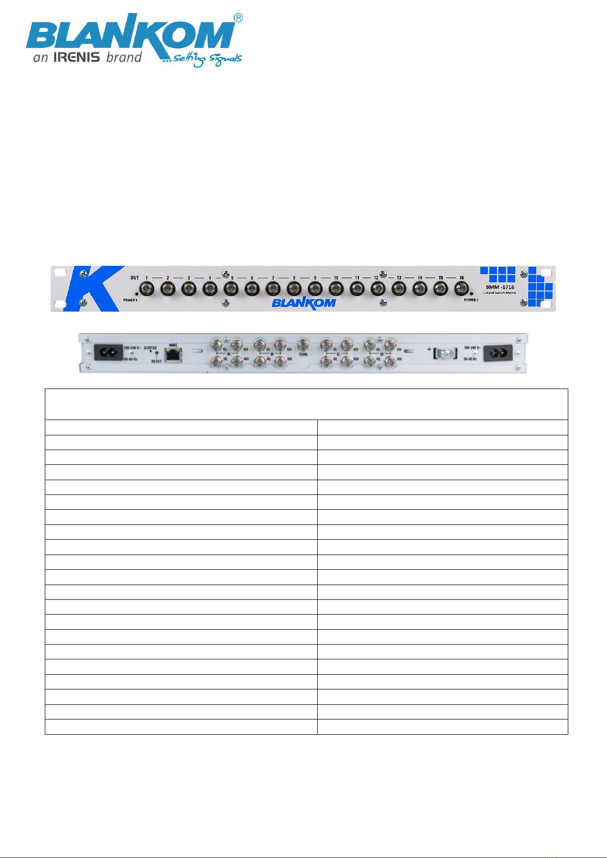
User Manual BMM-1716
All technical values are subject for changes w/o further notifications IRENIS GmbH © 2021
Vorwort
About This Manual
This manual is written for system integrators, IT technicians and knowledgeable end users. It provides information for
the installation and use of the Product described herein and in particular the knowledge and skills Satellite distribution
configurations of RF signals and measurements.
Über dieses Manual
Dieses Handbuch richtet sich an Systemintegratoren, IT-Techniker und sachkundige Endbenutzer. Es enthält Informationen
für die Installation und Verwendung des hier beschriebenen Produkts und insbesondere die Kenntnisse und Fähigkeiten von
Satellitenverteilungen und Ihren Konfigurationen von HF-Signalen und entsprechender Messungen.
Important Notes!
This manual is for use by qualified personnel only. Handling this device or system requires special electronic technical
knowledge. To reduce the risk of electrical shock or damage to the equipment, do not perform any servicing other than
the installation and operating instructions contained in this manual unless you are qualified to do so. This device operates
in the given voltage and frequency range without requiring manual adjustment.
Do not open the top case w/o unplugged power source because serious injury or death may be the result! Inside are
components under risk from electrostatic discharge. To avoid equipment damages do not touch these components or,
observe the respective handling rules! For continued protection against fire, the fuses may only be replaced by identical
fuses with the same electrical specifications which are designed for the corresponding fuse positions.
No part of this publication may be reproduced in any form or by any means or used to make any derivative work (such as
translation, transformation or adaptation) without the written permission from Blankom / IRENIS GmbH.
IRENIS GmbH reserves the right to revise this publication and make changes in its content from time to time, whereby it
shall not be obligatory for IRENIS GmbH to provide notification of such revision or change.
IRENIS GmbH provides this manual without warranty of any kind, neither implied nor expressed, this includes also any
warranties regarding the merchantability and fitness for a particular purpose. IRENIS GmbH may improve this manual or
make changes in the products described herein at any point of time.
Wichtige Anmerkungen!
Dieses Handbuch ist nur für qualifiziertes Personal vorgesehen. Die Handhabung dieses Geräts oder Systems erfordert
besondere elektronische & technische Kenntnisse. Um das Risiko eines elektrischen Schlags oder einer Beschädigung des
Geräts zu verringern, führen Sie keine anderen Wartungsarbeiten als die in diesem Handbuch enthaltenen Installations- und
Betriebsanleitungen durch, es sei denn, Sie sind dafür qualifiziert. Dieses Gerät arbeitet im angegebenen Spannungs- und
Frequenzbereich, ohne daß eine manuelle Einstellung erforderlich ist.
Öffnen Sie nicht das Gehäuse mit angeschlossener Stromquelle, weil schwere Verletzungen oder Tod die Folge sein können!
Im Inneren sind Komponenten, die durch elektrostatische Entladung gefährdet sind. Um Geräteschäden zu vermeiden,
berühren Sie diese Komponenten nicht oder beachten Sie die jeweiligen Handhabungsregeln! Zum weiteren Brandschutz
dürfen die Sicherungen nur durch identische Sicherungen mit den gleichen elektrischen Spezifikationen ersetzt werden, die
für die entsprechenden Sicherungspositionen ausgelegt sind.
Kein Teil dieser Veröffentlichung darf ohne schriftliche Genehmigung der BLANKOM / IRENIS GmbH in irgendeiner Formoder
auf irgendeine Weise reproduziert oder verwendet werden, um abgeleitete Werke (wie Übersetzung, Umwandlung oder
Anpassungen) zu machen.
Die IRENIS GmbH behält sich das Recht vor, diese Veröffentlichung zu überarbeiten und von Zeit zu Zeit inhaltliche
Änderungen vorzunehmen, wobei die IRENIS GmbH nicht verpflichtet ist, eine solche Überarbeitung oder Änderung zu
vermerken.
Die IRENIS GmbH stellt dieses Handbuch ohne jegliche Gewährleistung, weder stillschweigend noch ausdrücklich zur
Verfügung, dies beinhaltet auch Gewährleistungen hinsichtlich der Marktgängigkeit und Eignung für einen bestimmten Zweck.
Die IRENIS GmbH kann dieses Handbuch jederzeit verbessern oder Änderungen an den hier beschriebenen Produkten
vornehmen.