Iron Edison REVOLT4 IE51100RV4 User manual

User’s Guide
IE51100RV4
1

www.ironedison.com
Cover............................................................................................ 1
Table of Contents.....................................................................2
About User Manual......................................................2
Revision History.....................................................2
1.Safety Notices..................................................................... 3
2.Product Introduction........................................................ 4
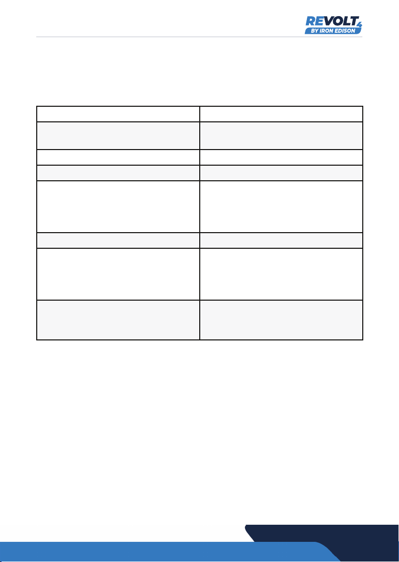
2.1 Product Specifications....................................................5
2.2 Battery Specifications.....................................................5
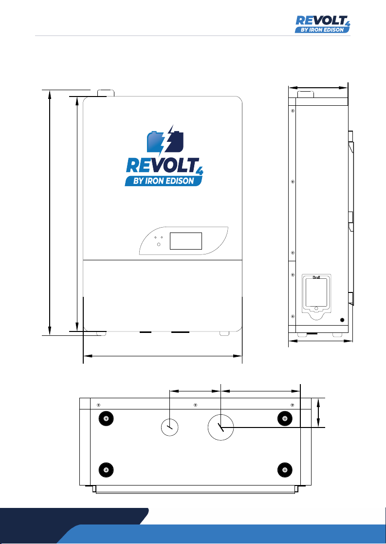
2.3 Structure Size.................................................................6
3.Storage and Transport.................................................... 7
3.1 Storage...........................................................................7
3.2 Transport........................................................................7
4.Installation Preparation.................................................. 7
4.1 Check the packing list.....................................................7
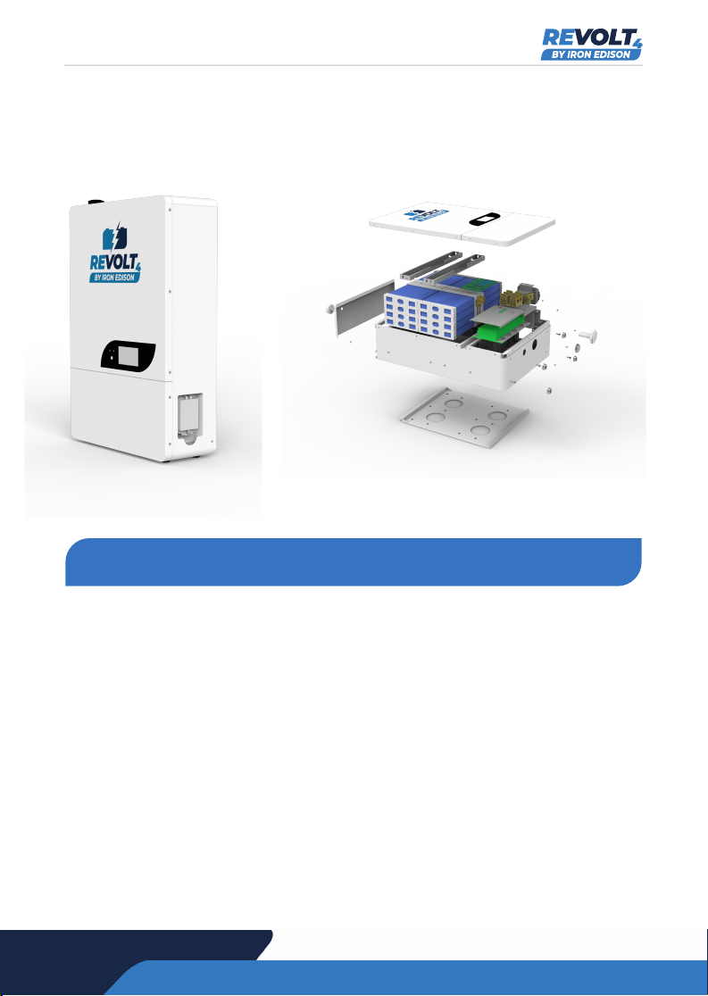
4.2 Product Picture...............................................................8
5.Battery Installation............................................................8
5.1 Installation Location....................................................... 9
5.1.1 Environment Requirement............................................9
5.1.3 Wall Mount Bracket Installation...................................10
5.1.4 Battery Pack Installation............................................. 11
5.2 Cable Connection...........................................................12
5.2.1 Connection Order.........................................................12
5.2.2 Disconnection Order....................................................13
5.2.3 Set the Address of the Dip Switches............................ 14
5.2.4 Wiring Diagram............................................................15
6.Commissioning...................................................................16
6.1 Operation........................................................................17
6.2 Battery Information Display.............................................20
7.Troubleshooting..................................................................22
About User Manual
This manual describes the installation, operation and maintenance of the
ReVolt battery system. This document will be updated periodically for
product revisions. Unless otherwise agreed, this document is to be used
only as a guide. All statements, information and recommendations in
this document do not constitute any express or implied warranty.
Revision History
12/08/2022 v.1.5
Table of Contents
2
b

www.ironedison.com
Any improper operation may lead to electrical shocks, burns and other
personal injury or equipment damage. Please read the important safety
information and strictly abide by all the safety rules of this instruction
manual.
The following is a list of the safety rules to be followed in order to op-
erate this product. Please refer to the warning note in the appropriate
section for the safety instructions in the use and maintenance process.
For maximum battery performance and longevity, we recommend install-
ing the battery in a temperature-controlled environment.
Do not touch the live parts of the equipment without confirming the volt-
age and temperature of the equipment.
Only professional electricians or professionally qualied personnel can
install, operate, overhaul, and maintain the equipment. During the main-
tenance or overhaul, there must be at least two people equipped with ap-
propriate PPE (personal protective equipment) to include: safety shoes,
protective glasses, insulated gloves and electrically insulated tools. The
personnel must also be trained in how to recognize electrical hazards
and how to mitigate them.
Warning: Violation of the following provisions may result in personal
injury or equipment damage.
When moving, transporting and placing equipment, the equipment must
be placed horizontally. This will prevent the battery from tipping over.
The battery should be installed on a re-retardant material. Do not place
ammable materials inside or on top of the battery enclosure.
Do not install the battery on a plywood sheet.
Do not leave cloth, paper, metal shavings, tools or other foreign objects
inside the battery enclosure.
1. Safety Notices
3

www.ironedison.com
In non-emergency cases, do not stop the operation of the monitoring
system by connecting and disconnecting input power cables.
The battery enclosure can be cleaned using a soft cloth.
To ensure proper operation over the life of the battery, use the monitoring
software to check that each battery is operating properly. No regular
maintenance needs to be performed inside the enclosure.
Electrostatic Warning
Any personnel who comes into contact with the circuit boards or internal
components needs to wear a good anti-static grounding bracelet. In the
event of replacing circuit boards, please hold the edge in order to prevent
damage from static electricity. In addition, static electricity can be elimi-
nated by contacting electrically conductive bodies such as metal sheets.
Reminders/Notications
When debugging the battery and solar system, please pay attention to
the messages displayed on the touch screen.
This Lithium Iron Phosphate battery system is integrated with an ad-
vanced Battery Management System (BMS) which includes charge/
discharge management, thermal management, communication man-
agement, balance management, and data management. This system
also allows for remote battery performance monitoring, remote device
management and system maintenance.
The product features a long lasting lithium iron phosphate battery chem-
istry. This high eciency system is compact in size, comparably light
weight, and provides stable long-term performance. The product is safe
and eco-friendly, while also being adaptable and usable in high altitude
environments.
2. Product Introduction
4

www.ironedison.com
2.1 Product Specications
System Model (see nameplate) IE51100RV4
2.2 Battery Specications
Model Code IE
Nominal Voltage 51.2
Nominal Capacity 100 Ah
Battery Type LiFePO4
Model Number REVOLT4
Item Specication
Battery Type LiFePO4
Nominal Voltage 51.2
Nominal Capacity 100Ah
Nominal Energy5.12 kWh
Standard Charge Voltage 55.2 V
Recommended Float Charge Voltage 53.4 V
Maximum Continuous Charge Current 100 A
Maximum Continuous Discharge Current 100 A
Peak Discharge Current (3 seconds) 300 A
Maximum Continuous discharge power 5 kW
Peak Discharge Power (3 seconds) 15 kW
Weight 127 LBS
5

www.ironedison.com
2.3 Structure Size
POWERCOM
454mm (177/8")
670mm (263/8")
698mm (271/2")
57mm (21/4")
101mm (4") 177mm (7")
171mm (63/4")
171mm (63/4")
6

www.ironedison.com
3.1 Storage
The battery should be stored in a dry, clean, shaded and well-ven-
tilated area.
The battery needs to be charged to at least 70% before storing it.
Store the battery modules for no longer than 6 months.
Keep the battery from dropping, turning over and any other seri-
ous impact.
Keep away from children and pets.
3.2 Transport
Lithium-ion batteries are hazardous goods. Therefore the fol-
lowing points must be observed when transporting the battery
modules:
• Observe the general transport regulations based on the
mode of transport as well as all legal regulations for haz-
ardous goods.
• Keep batteries face up and do not allow them to fall over.
Batteries in their boxes should not be stacked more than
three tall.
• Check the battery immediately after transport.
•If the user nds shell deformation on the battery pack, do
not use it and immediately contact Iron Edison.
3. Storage and Transport
4.1 Check the packing list
Item Specication
Communication cable RJ45+RJ45 150mm length 1pcs
Terminal matching resistance 120 ohm RJ45 1pcs
Wall mounting bracket 1pcs
Expanding screw 10pcs
4. Installation Preparation
7

www.ironedison.com
4.2 Product picture
Battery Pack:
Please follow the owchart below to install the battery system.
Start
Read the manual
Site Selection
Install wall mounting bracket
Install the battery pack
Connect the cables
Commission: Set parameters in inverter/charger
Normal Operation
a. Yes - End
b. No - Troubleshooting
5. Battery Installation
Expanded View:
8

www.ironedison.com
5.1 Installation location
5.1.1 Environment Requirement
Application Scenarios Residential Battery
Operating Environment Indoors and out of range from
strong electromagnetic radiation
Operating Temperature 0 to 45 C (32 - 110 F)
IP Grade IP 55
Storage Temperature Short time (<1 month) -20 to 45 C
(-4 to 110 F)
Long time (>1 month) 15 to 35 C
(59 to 95 F)
Operating Humidity 0-85%
Max discharge current vs. Altitude 100 Amps @ < 2000 meters
(<6561ft.) 90 Amps @ 2000
meters - 4000 meters
(6561 ft - 13,123 ft.)
Case Ground Requirement Use at least 2mm2 (#14 AWG)
copper wire with the resistance
of less than 1 ohm
The total weight of the battery is 58kg (127lbs). Please ensure
that the wall or load-bearing wall studs are strong enough to
withstand hanging the battery.
Recommended clearances for the left, right, top and bottom of
the battery are shown below. Clearances are required for
proper ventilation and ease of use.
9

www.ironedison.com
100mm (4in) left
100mm (4in) top
100mm (4in) right
200mm (8in) bottom
Attention
The battery should be installed and ventilated in a cool, dry
place. Ensure the battery is installed away from any heat source
or direct sunlight.
For maximum battery performance and longevity, we highly
recommend installing the battery in a temperature-controlled
environment. (Air conditioned spaces for warm climates and
heated spaces for cold climates)
Failure to follow these instructions may result in the battery
cutting off power output or system failure due to over or under
temperature.
Keep the battery away from any strong electromagnetic elds to
prevent problems with either the battery communication and/or
the internal power supply. Common sources of electromagnetic
interference are inverters, chargers, and transformers.
Keep away from ammable and explosive materials.
5.1.3 Wall mount bracket Installation
a. Mark the hole’s position with a pen.
b. Drill holes with a diameter of 12mm (.47in) with an electric
drill
c. Hammer or screw the M8x60 expansion screws into the
holes.
10

www.ironedison.com
5.1.4 Battery pack installation
a. Loosen the 2 bolts
b. Align the flange on the back of the battery with the bottom
edge of the mounting plate
c. Lower the battery chassis flange onto the mounting plate
d. Secure the bracket at the top of the battery with screws
e. Re-lock the battery pack again with these 2 bolts
11

www.ironedison.com
5.2 Cable Connection
5.2.1 Connection Order
When assembling, please follow the process below.
Process No. Description
1 Set the module communication address using the Dip
Switches
2Connect the Module COM cable (RJ45 connector)
between battery modules
3 Connect Inverter COM Cable between the Master
Module and the inverter.
4 Connect the battery Power Cable to the Bus-bar
5 Connect the Bus-bar to the inverter
6 Close the inverter breaker and each battery pack’s DC
breaker at the combiner
7 Press and hold each module’s power button until the
RUN LED ashes to power on the modules
8 Program and commission system
12

www.ironedison.com
5.2.2 Disconnection Order
Process No. Description
1 Stop Charge or Discharge
2 Press each module’s switch until the RUN LED turns off
on each module
3 Open the inverter circuit breaker and each battery
pack’s DC breaker at the combiner
4 Disconnect the cables from the battery
5 Disconnect the Inverter Module COM cable (RJ45 con-
nector) to the battery module
6 Remove the battery
7 Reconnect the COM cable to the remaining batteries
8 Reset the Dip Switches with the remaining batteries
A short circuit will occur in the event of reversing a battery’s negative
and positive cables. Use extreme caution to not reverse polarity when
connecting the battery cables.
13

www.ironedison.com
5.2.3 Set the Address of the Dip Switches
Module Number #1 #2 #3 #4
Single Module OFF OFF OFF OFF
1st Master Module OFF ON OFF OFF
2nd Slave Module OFF ON OFF OFF
3rd Slave Module ON ON OFF OFF
4th Slave Module OFF OFF ON OFF
5th Slave Module ON OFF ON OFF
6th Slave Module OFF ON ON OFF
7th Slave Module ON ON ON OFF
8th Slave Module OFF OFF OFF ON
9th Slave Module ON OFF OFF ON
10th Slave Module OFF ON OFF ON
11th Slave Module ON ON OFF ON
12th Slave Module OFF OFF ON ON
13th Slave Module ON OFF ON ON
14th Slave Module OFF ON ON ON
Note: When only one battery module is used, set the address as single.
When multiple battery modules are used in parallel, set their address as
1-14. For systems with more than 15 batteries, contact Technical
Support.
14

www.ironedison.com
5.2.4 Wiring Diagram
Notes:
1. Use at least AWG 1/0 cable as the battery output power wire.
2. Each battery should connect to the inverter (or combiner bus-bar)
with identical cable length.
3. Insert the 120 ohm resistor inside the RJ45 connector into the
batteries at either end of the string of batteries. For example, with
with four batteries, insert the resistor into battery #1 and battery
#4. Inserting a resistor in the middle of a string of batteries may
lead to battery communication failure and the system may stop
working.
5.2.5 RJ45 Communication Cable Pin Denition
1” Master
120_RJ11
Module Communication Cable (RJ11 Connector)Inverter Communication Cables
Inverter +
Inverter - Bus-bar
2nd Slave Nnd Slave
Battery
Output
Battery
Output
Battery
Output
15

www.ironedison.com
CAN CAN RS485
Pin No. Denition
1 NC
2 NC
3 CANL
4 CANL
5 CANH
6 CANH
7 NC
8 NC
Pin No. Denition
1 Inverter RS485B
2 Inverter RS485A
3 NC
4 NC
5 NC
6 NC
7 BMS debug RS485A
8 BMS debug RS485B
Both of two CAN port RS485 port
LCD Screen, Power Button, Run and Alarm LEDs 6.1 Operation
6. Commissioning
16

www.ironedison.com
6.1 Operation
• Start-up: Close the inverter’s main DC breaker. Close DC
breaker for batteries. Press the power button until the RUN
LED flashes (at least 2 seconds). Wait 5 seconds for the
pre-charge function to initiate. Press the inverter’s power
button to start the inverter.
• Operating: If the battery is operating without any alarms, the
RUN green LED light will be ON and the battery will maintain
output. In operating mode, the LCD screen will be illuminat-
ed for 1 minute when the user presses the power button
(short press 1 second).
• Alarm: When the battery is in the alarm mode (protected),
the related warning signs on the LCD screen will be ON and
the red ALARM LED light will be ON.
• Turn-Off: Press the power button for 3 seconds until the
LCD screen and SOC LEDbar turns off. Then the battery
output will turn off.
Alarm Specication Parameter
Over charge Overcharge alarm for
each cell
3.55 +/- 0.03V (nodis-
play in LCD or alarm LED)
Over charge Overcharge protection
for each cell
3.75 +/- 0.03V, Delay
time: 1s (not display in
LCD or alarm LED)
Over charge Overcharge release for
each cell 3.45+/- 0.03V
Over charge Over charge alarm for
total voltage 55.8V +/- 0.5V
Over charge Over charge protection
for the total voltage
56.0V +/- 0.5V for 1 +/-
sec
Over charge Over charge release for
total voltage 55.6V +/- 0.5V
Over charge Over charge release
method Under the release voltage
17

www.ironedison.com
Alarm Specication Parameter
Over discharge Over discharge alarm for
each cell 2.9 +/- 0..03V
Over discharge Over discharge protec-
tion for each cell
2.8+/- 0.03V,
Delay time:1s
Over discharge Over discharge release
for each cell 3.0 +/- 0.03V
Over discharge Over discharge alarm for
total voltage 47.2V +/- 0.5V
Over discharge
Over discharge protec-
tion for the total
voltage
46.4V +/- 0.5V for 1 +/-
0.5 sec
Over discharge Over discharge release
for total voltage 48V +/- 0.5V
Over discharge Over discharge release
method Charge to Recovery
Alarm Specication Parameter
Over current Charge over current
alarm 110 +/- 5A
Over current Charge over current
protection 120 +/- 5A for 5 +/- 1sec
Over current Charge over current
release method
After release after 1
minute
Over current Discharge over current
alarm 110 +/- 5 Amps
Over current Discharge over current
protection
120 +/- 10 Amps for 5
+/- 1sec
Over current Over current release
method
Auto release after 1
minute
18

www.ironedison.com
Alarm Specication Parameter
Over temperature Charge over temperature alarm 49 +/- 3 C
Over temperature Charge over temperature protection 51+/- 3 C
Over temperature Charge over temperature release 45 +/- 3 C
Over temperature Discharge over temperature alarm 60 +/- 3 C
Over temperature Discharge over temperature
protection 65 +/- 3 C
Over temperature Discharge over temperature release 55 +/- 3 C
Alarm Specication Parameter
Under temperature Charge over temperature alarm 3 +/- 3 C
Under temperature Charge under temperature
protection 0 +/- 3 C
Under temperature Charge under temperature release 5 +/- 3 C
Under temperature Discharge under temperature
alarm -15 +/- 3 C
Under temperature Discharge under temperature
protection -20 +/- 3 C
Under temperature Discharge under temperature
release -10 +/- 3 C
Alarm Specication Parameter
SOC Low SOC Alarm 10%
19

www.ironedison.com
6.2 Battery Information Display
Press and hold the power button for one second to
activate the LCD screen (there is a delay for the screen to
activate).
Supplementary instructions
Display Indicator Note
Battery voltage
Residual energy
Current power
Negative value indicates
discharging. Positive value
indicates charging.
SOC State of Charge
Cycle Number
Battery temperature
20
Table of contents
Other Iron Edison Camera Accessories manuals
Popular Camera Accessories manuals by other brands

Perun
Perun AL C20 instructions

Sony
Sony FCB-CX45CP Technical manual

GNB
GNB Flooded Classic series Installation & operating instructions

Bioenno Power
Bioenno Power BLF-1206A Instructions for use

EnerSys
EnerSys DataSafe 12HX1000F-FR Installation, operation and maintenance instructions

Motorola
Motorola VERVE CAM user guide