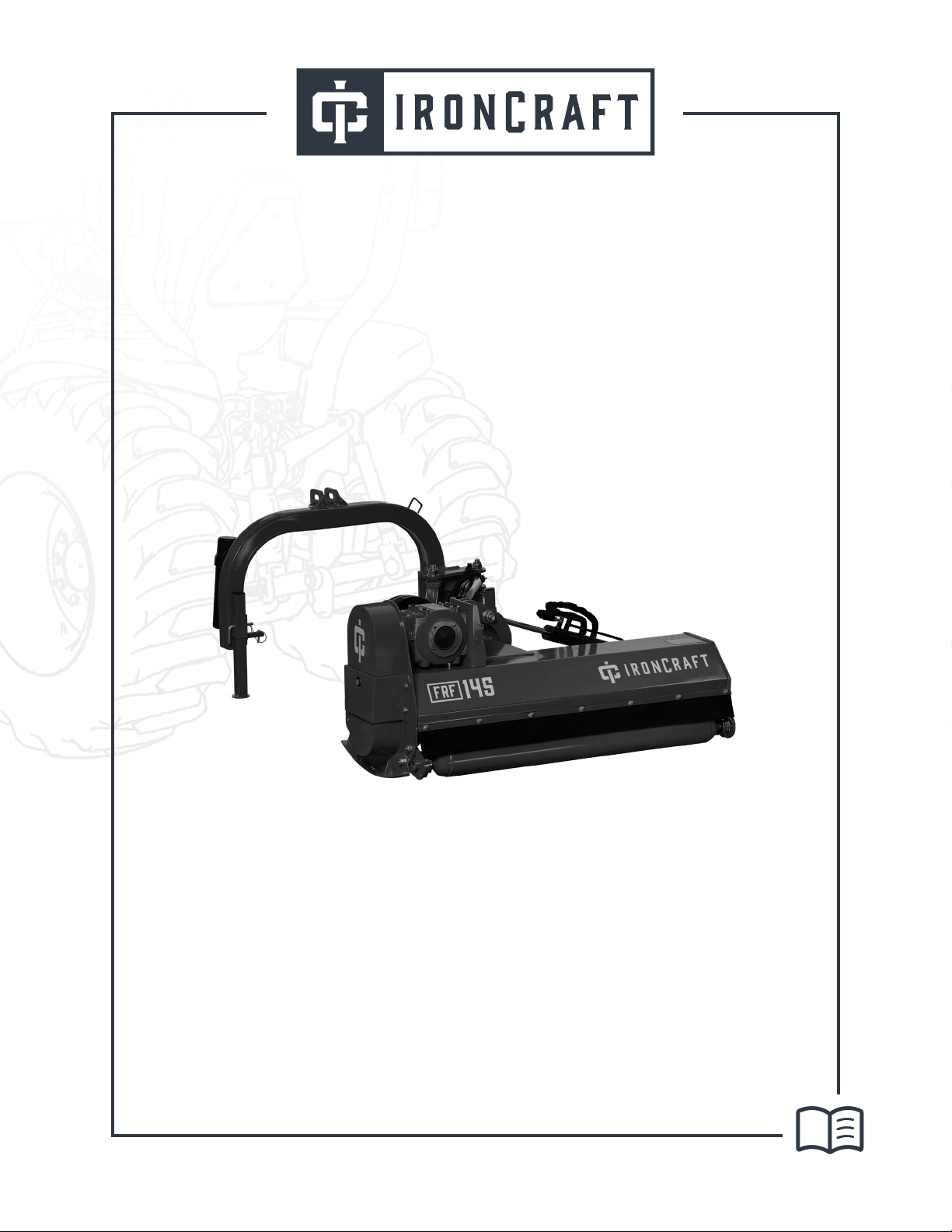
IronCraft FRF Series Application guide

FRF SERIES
OFFSET FLAIL MOWER
OPERATION & PARTS MANUAL
Read and understand the manual. is manual provides information and procedures to
safely operate and maintain the FRF Series Oset Flail Mower.
August 2023

Ironcraftusa.com
English
2
TABLE OF CONTENTS
Start Here. . . . . . . . . . . . . . . . . . . . . . . . . . . . . . . . . . . . . . . . . . . . . . . . . . . . . . . . . . . . . . . . . . . . . 3
Important Safety Information . . . . . . . . . . . . . . . . . . . . . . . . . . . . . . . . . . . . . . . . . . . . . . . . . . . 5
Safety Labels . . . . . . . . . . . . . . . . . . . . . . . . . . . . . . . . . . . . . . . . . . . . . . . . . . . . . . . . . . . . . . . . . . 8
Introduction . . . . . . . . . . . . . . . . . . . . . . . . . . . . . . . . . . . . . . . . . . . . . . . . . . . . . . . . . . . . . . . . . . 9
Section 1: Assembly and Set-up . . . . . . . . . . . . . . . . . . . . . . . . . . . . . . . . . . . . . . . . . . . . . . . . . 10
Section 2: Operating Instructions . . . . . . . . . . . . . . . . . . . . . . . . . . . . . . . . . . . . . . . . . . . . . . . 11
Section 3: Adjustments . . . . . . . . . . . . . . . . . . . . . . . . . . . . . . . . . . . . . . . . . . . . . . . . . . . . . . . . 12
Section 4: Maintenance and Lubrication . . . . . . . . . . . . . . . . . . . . . . . . . . . . . . . . . . . . . . . . . 13
Section 5: Specications & Capacities . . . . . . . . . . . . . . . . . . . . . . . . . . . . . . . . . . . . . . . . . . . 15
Section 6: Troubleshooting . . . . . . . . . . . . . . . . . . . . . . . . . . . . . . . . . . . . . . . . . . . . . . . . . . . . . 17
Section 7: Appendix . . . . . . . . . . . . . . . . . . . . . . . . . . . . . . . . . . . . . . . . . . . . . . . . . . . . . . . . . . . 18
Section 8: Parts illustration . . . . . . . . . . . . . . . . . . . . . . . . . . . . . . . . . . . . . . . . . . . . . . . . . . . . . 20
Table of COntents

Ironcraftusa.comStart Here 3
English
START HERE
Never carry out maintenance or cleaning work unless the PTO has been disengaged,
the engine switched off, the hand brake engaged, and the tractors wheels chocked
in position by a block or stone under the wheels.
Congratulations! You’ve just added an IronCra attachment to your arsenal. If you
have any questions about how to use your new oset ail mower - don’t hesitate to reach
out to your local IronCra dealer!
Tractor Check
Before starting the machine, check that your tractor matches the
required horsepower to run properly. You’ll be glad you did.
Register Your warranty
Help us help you in case of a manufacturing defect or meteor strike* using
the information on page #4. * = meteor strike not covered by warranty.
After the rst 2 operating hours,
check that all screws and bolts are correctly torqued.
Check the condition of the machine
Check all parts (cardan shaft, hammers, knives, belts) to make sure they
haven’t been damaged during transport and that the accessories are
complete and in good condition.
01
02
03
05
Check the greasing points and oil levels
Refer to gure #1 (page #5) for grease points, oil type, and greasing
frequency.
Enjoy!
You’re now ready to make the toughest terrain bow to your will.
04
06

Ironcraftusa.com
English
Important Safety Information 4
In addition to design and conguration of equipment, hazard control and accident prevention are
dependent upon the awareness, concern, prudence and proper training of personnel involved in the
operation, transport, maintenance and storage of equipment.
IMPORTANT SAFETY INFORMATION
SAFETY ALERTS
Do not allow anyone to operate this equipment who has not fully read and
comprehended this manual and who has not been properly trained in the safe
operation of the equipment.
The SAFETY ALERT SYMBOL indicates there is a potential hazard to personal safety
involved and extra safety precaution must be taken. When you see this symbol, be alert
and carefully read the message that follows it.
1. Operator should be familiar with all functions of the unit.
2. Operate implement from the driver’s seat only.
3. Make sure all guards and shields are in place and secured before operating the implement.
4. Do not leave tractor or implement unattended with engine running.
5. Dismounting from a moving tractor could cause serious injury or death.
6. Do not stand between tractor and implement during hitching.
7. Keep hands, feet, and clothing away from power-driven parts.
8. Wear snug tting clothing to avoid entanglement with moving parts.
9. Watch out for wires, trees, etc., when raising implement. Make sure all persons are clear of
working area.
10. Turning tractor too tight may cause implement to ride up on wheels. This could result in injury
or equipment damage.
Thoroughly read and understand the instructions given in this manual before operation.
Refer to the “Safety Decal”, read all instructions noted on them.
DANGER
WARNING
CAUTION

Ironcraftusa.comImportant Safety Information 5
English
SHUTDOWN AND STORAGE
USE SAFETY LIGHTS AND DEVICES
• Lower machine to ground, put tractor in park, turn o engine, and remove the ignition key.
• Detach and store implements in a area where children normally do not play. Secure implement
by using blocks and supports.
• Slow moving tractors, self-propelled equipment, and towed implements can create a hazard
when driven on public roads. They are dicult to see, especially at night.
• Flashing warning lights and turn signals are recommended whenever driving on public roads.
Use lights and devices provided with implement.
BE AWARE OF SIGNAL WORDS
A signal word designates a degree or level of hazard seriousness. The signal words are:
Indicates an imminently hazardous situation which, if not
avoids, will result in death or serious injury. This signal
word is limited to the most extreme situations, typically
for machine components that, for functional purpose,
cannot be guarded.
Indicates a potentially hazardous situation which, if
not avoided, could result in death or serious injury, and
includes hazards that are exposed when guards are
removed. It may also be used to alert against unsafe
practices.
Indicates a potentially hazardous situation which, if not
avoided, may result in minor or moderate injury. It may
also be used to alert against unsafe practices.
DANGER
WARNING
CAUTION
For your protection Thoroughly read and understand the “safety label” section,
read all instructions noted on them.

Ironcraftusa.com
English
Important Safety Information 6
TRANSPORT MACHINERY SAFELY
• Comply with state and local laws.
• Maximum transport speed for implement is 20 mph. Do not exceed. Never travel at a speed
which does not allow adequate control of steering and stopping. Some rough terrain require a
slower speed.
• Sudden braking can cause a towed load to swerve and upset. Reduce speed if towed load
is not equipped with brakes.
• Use the following maximum speed - tow load weight ratios as a guideline:
20 mph when weight is less than or equal to the weight of tractor.
10 mph when weight is double the weight of tractor.
• IMPORTANT: Do not tow a load that is more than double the weight of tractor.
TRANSPORT MACHINERY SAFELY
• Riders obstruct of operator’s view, they could be struck by foreign objects or thrown from the
machine.
• Never allow children to operate equipment.
PRACTICE SAFE MAINTENANCE
• Understand procedure before doing work. Use proper tools and equipment. refer to
Operator’s Manual for additional information.
• Work in a clean dry area.
• Lower the implement to the ground, put tractor in park, turn o engine, and remove key
before performing maintenance.
• Allow implement to cool completely.
• Do not grease or oil implement while it is operation.
• Inspect all parts. Make sure parts are in good condition and installed properly.
• Remove buildup of grease, oil or debris.
• Remove all tools and unused parts from implement before operation.
PREPARE FOR EMERGENCIES
• Be prepared if a re starts.
• Keep a st aid kit and re extinguisher handy.
• Keep emergency numbers for doctor, ambulance, hospital and re department near phone.
WEAR PROTECTIVE EQUIPMENT
• Protective clothing and equipment should be worn.
• Wear clothing and equipment appropriate for the job. Avoid loose tting clothing.
• Prolonged exposure to loud noise can cause hearing impairment or hearing loss. Wear
suitable hearing protection such as earmus or earplugs.
• Operating equipment safely requires the full attention of the operator. Avoid wearing
radio headphones while operating machinery.

Ironcraftusa.comSafety Labels 7
English
AVOID HIGH PRESSURE FLUIDS HAZARD
• Escaping uid under pressure can penetrate the skin causing serious injury.
• Avoid the hazard by relieving pressure before disconnecting hydraulic lines.
• Use a piece of paper or cardboard, not body parts, to check for suspected leaks. Wear
protective gloves and safety glasses or goggles when working with hydraulic systems.
• If an accident occurs, see a doctor immediately. Any uid injected into the skin must be
treated within a few hours or gangrene may result.
SAFETY LABELS
Your Flail Mower comes equipped with all safety labels in place. They were designed to help you
safely operate your implement. Read and follow their directions.
1. Keep all safety labels clean and legible.
2. Replace all damaged or missing labels. To order new labels go to your nearest Ironcraft dealer or
visit our dealer locator at IroncraftUSA.com.
3. Some new equipment installed during repair requires safety labels to be axed to the replaced
component as specied by Cosmo. When ordering new components make sure the correct safety
labels are included in the request.
4. Refer to this section for proper label placement. To install new labels:

Ironcraftusa.com
English
Introduction 8
INTRODUCTION
IronCraft welcomes you to the growing family of new product owners. This implement has been
designed with care and built by skilled workers using quality materials. Proper assembly, maintenance,
and safe operating practices will help you get years of satisfactory use from the machine.
APPLICATION
The Flail Mowers are designed for Category 1 - three point hitch or Quick-Hitch System mounting.
These Fixed Bar Flail Mowers are ideal for ripping, leveling, nish grading, and backlling applications
at feedlots, outdoor arenas, building sites, and maintenance operations on farm and ranch lanes or
roadways.
USING THIS MANUAL
• This Operator’s Manual is designed to help familiarize you with safety, assembly, operation,
adjustments, troubleshooting, and maintenance. Read this manual and follow the
recommendations to help ensure safe and ecient operation.
• The information contained within this manual was current at the time of printing. Some parts
may change slightly to assure you of the best performance.
• To order a new Operator’s or Parts Manual contact your authorized dealer. Manuals can also be
printed from the Cosmo Service & Support Center by your dealer.
TERMINOLOGY
“Right” or “Left” as used in this manual is determined by facing the direction the machine will
operate while in use unless otherwise stated.
DEFINITIONS
“Note:” A special point of information that the operator must be aware of before continuing.
“Important:” A special point of information related to its preceding topic. The intention is that this
information should be read and noted before continuing.
OWNER ASSISTANCE
The Warranty Registration card should be lled out by the dealer at the time of purchase. This
information is necessary to provide you with quality customer service. If customer service or repair
parts are required contact a dealer. A dealer has trained personnel, repair parts and equipment
needed to service the machine.
The parts on your machine have been specially designed and should only be replaced with genuine
parts.
SERIAL NUMBER PLATE
For prompt service always use the serial number and model number when ordering parts from your
dealer. Be sure to include your serial and model numbers in correspondence also.

Ironcraftusa.comSection 1: Assembly and Set-up 9
English
SECTION 1: ASSEMBLY AND SET-UP
TRACTOR REQUIREMENTS
This mower is designed with a 3-Point category I hitch. Tractor horse power rating should not exceed
80 PTO horse power.
ASSEMBLY
Refer to the parts illustration.
TRACTOR HOOK-UP
• Be certain that tractor draw bar will not interfere. Move draw bar ahead or remove if
required. Draw bar should also be checked for clearance when unit is being raised for the
rst time.
• Align lower link arms of tractor to hitch clevises on mower. Insert lower hitch pins into
lower ball swivels and attach linch pins.
• Attach tractor top link to upper oating hitch on mower with pin supplied. Secure with
lock pin.
• Adjust tractor top link in or out to place upper hitch pin vertically above or slightly behind
lower hitch pins to allow mower otation. The mower should be run with the back 15
degrees lower than the front.
DRIVELINE INSTALLATION
• Slide driveline end with extended safety cone over splined shaft of gearbox and secure
with attaching device.
• Slide driveline over tractor’s splined PTO shaft and secure with locking device of driveline.
• Driveline should now be moved back and forth to insure that it is secure on the PTO shaft
of the tractor and mower gearbox.
• Attach chain from the driveline shield to one of the upper hitch braces to ensure that the
shield does not rotate.
• Should driveline require shortening:
• Hold the half-shafts next to each other in the shortest working position and mark them.
• Shorten inner and outer guard tubes equally.
• Shorten inner and outer sliding proles by the same length as the guard tubes.
• Proper overlap is a minimum of one-half the length of each tube, with both tubes being
of equal length.
• Round o all sharp edges and remove burrs. Grease sliding proles.
Tractor PTO shield and all mower guards must be
in place at all times during operation!
CAUTION

Ironcraftusa.com
English
Section 2: Operating Instructions 10
SECTION 2: OPERATING INSTRUCTIONS
TRANSPORTING
NOTE: Always disengage PTO before raising mower to transport position.
• When raising the mower to transport position, be sure that driveline does not contact
tractor or mower. Adjust and set the tractor’s 3-point hitch lift height so that the driveline
does not contact mower deck in the fully raised position.
• Be sure to reduce tractor ground speed when turning, leaving enough clearance so that the
mower does not contact obstacles such as buildings, trees or fences.
• Select a safe ground travel speed when transporting from one area to another. When
traveling on roadways, transport in such a way that faster moving vehicles may pass safely.
• When traveling over rough or hilly terrain, shift tractor to a lower gear.
When traveling on public roads, whether at
night or during the day, use accessory lights and
devices for adequate warning to operators of
other vehicles. Comply with all Federal, State,
and local laws.
CAUTION
MOWING INSTRUCTIONS
• Clear area to be mowed of objects and debris that might be picked up and thrown by the
mower blades.
• Grass is best cut when it is dry. Mowing wet grass can cause plugging resulting in grass
clumps behind the mower.
• Grass should be mowed frequently as shorter clippings deteriorate faster.
• If mowing extremely tall grass, it is best to raise cutting height and mow the area, then
lower cutting height and mow a second time at the desired height.
OPERATING INSTRUCTIONS
Proper servicing and adjustments are the key to the long life of any machine. With careful and
systematic inspection of the mower, costly maintenance, time and repair can be avoided.
Before beginning to mow, the following inspection should be performed:
• Check oil level in gearbox.
• Check that all plugs in gearbox have been replaced and tightened properly.
• Be sure all mower knives, bolts and nuts are tight.
• Be certain all guards and shields are in place and secure.
• Grease driveline shaft and all other grease ttings.
• Clear area to be mowed of rocks, branches and other foreign objects.
• Lower mower to ground. Set tractor throttle at approximately 1/4 open. Engage PTO to

Ironcraftusa.comSection 2: Operating Instructions 11
English
start blades rotating.
• Operate with 540 rpm PTO tractor.
• At rst begin mowing at a slow forward speed and shift up until the desired speed is
achieved - maintaining 540 PTO rpm.
• Mower knives will cut better at a faster blade speed than at reduced throttle.
• After mowing the rst 50 feet, stop and check to see that the mower is adjusted properly.
• Do not make sharp turns or attempt to back up while mower is on the ground.
• Do not engage PTO with mower in the fully raised position. Do not engage PTO at full
throttle.
SECTION 3: ADJUSTMENTS
LEVELING THE MOWER
NOTE: Tractor and mower should be on level ground.
Leveling can be adjusted at the tractor’s 3-point arms and center link.
CUTTING HEIGHT ADJUSTMENT
The machines cutting height depends upon the position of the rear roller.
• Remove the bolts that x the roller on both sides.
• Lift or lower both sides of roller in equal measurements.
• Replace bolts and re-tighten.
3-POINT HITCH ADJUSTMENTS
The 3-point hitch system on this mower has been designed for front to back otation when mowing
on uneven terrain. Adjust tractor’s top center link to place the upper hitch pin vertically above or
slightly behind the lower hitch pins. The mower should be run with the back 15 degrees lower than
the front.
• The hitch can also be adjusted from side to side by turning the adjustment handle. Turn
handle until you have achieved your desired location.
Engage parking brake, shut off tractor, remove
key and disengage PTO before making any height
adjustments!
CAUTION

Ironcraftusa.com
English
Section 3: Adjustments 12
The Belt tension should be checked after the rst 20 hours of use. And then every 40 hours of use.
• Tension on the belt can be adjusted with the belt tension bolt. Turn the bolt until desired
tension is achieved. When the belt has the correct tension the gearbox should be adjusted
so that the gearbox extension is running straight (parallel) with the ail mower. Loosen
bolts at the bottom of the gearbox and move gearbox until gearbox extension is running
straight.
• Excessive tension on the belt may lead to premature failure of belt and drive components.
Belt drive system under spring tension; use care
to avoid bodily harm!
CAUTION
BELT TENSION
SECTION 4: MAINTENANCE AND LUBRICATION
Excessive tension on the belt may lead to
premature failure of belt and drive components.
Excessive tension on the belt may also lead to a
safety hazard to the operator or bystanders.
CAUTION
For safety reasons, each maintenance operation
must be performed with tractor PTO disengaged,
mower lowered completely to ground and tractor
engine shut off with ignition key removed.
CAUTION
MAINTENANCE
Proper servicing and adjustment is the key to the long life of any farm implement. With careful and
systematic inspection, you can avoid costly maintenance, time and repair.
• After using the mower for several hours, check all bolts to be sure they are tight and check
drive belt tension.
• Replace any worn, damaged or illegible safety decals by obtaining new decals from dealer.

Ironcraftusa.comSection 4: Maintenance and Lubrication 13
English
1. Remove belt guard fender and belt cover.
2. Disengage belt tension by loosening belt tension bolt until belt can be removed.
3. With tension relieved from belt remove old belt from pulleys.
4. Tighten belt tension bolt.
5. Reinstall belt guard and belt guard fender.
STORAGE
At the end of the working season or when the mower will not be used for a long period, it is good
practice to clean o any dirt or grease that may have accumulated on the mower and any of moving
parts.
1. Clean as necessary.
2. Check knives for wear and replace if necessary.
3. Inspect mower for loose, damaged or worn parts and adjust or replace as needed.
4. Store unit inside if possible for longer life.
5. Repaint parts where paint is worn or scratched to prevent rust.
6. Replace all damaged or missing decals.
LUBRICATION
Driveline Shaft U-Joints
Type of Lubrication: Multi-purpose Grease
Roller Bearing (Both Ends)
Type of Lubrication: Multi-purpose Grease
KNIFE REPLACEMENT
IMPORTANT: Make sure that the knife is the same length as the others on the mower. This will keep
the rotor rotation balanced.
1. Remove bolt and nut.
2. Remove old knife.
3. Install new knife and existing bolt.
4. Secure with nut.
V-BELT INSTALLATION
Belt drive system under spring tension; use care
to avoid bodily harm!
CAUTION

Ironcraftusa.com
English
Section 5: Specifications & Capacities 14
Cutter Rotor Bearing (Both Ends)
Type of Lubrication: Multi-purpose Grease
Gearbox
Type of Lubrication: SAE 90W Gear Lube
Check oil level in gearbox by removing the plug
located on the right hand side. Oil should be level
with bottom of plug hole. Add oil if necessary by
removing top ll plug and side plug. Add oil until
it ows from side plug hole.
Do not overll!
IMPORTANT: Mower should be level when
checking oil in gearbox!
Driveline Proles
Type of Lubrication: Multi-purpose Grease
SECTION 5: SPECIFICATIONS & CAPACITIES
FRF125 FRF145 FRF165
TRACTOR HP 20-40 HP 30-45 HP 40-50 HP
WEIGHT 630 lb 672 lb 703 lb
Cutting WIDTH 47 in 55 in 63 in
# of Hammer Blades 20 24 28
HAMMER DIMENSIONS 3.4 in x 1.7 in
SIDE TRANSMISSION 3 BELTS 3 BELTS 4 BELTS
ROTOR DIAMETER 4.2 in
ROLLER DIAMETER 4.7 in
PTO SHAFT SERIES 4

Ironcraftusa.comSection 5: Specifications & Capacities 15
English
a b-1 b-2 c d
FRF125 1250mm 1254mm 1507mm 689mm 1747mm
FRF145 1450mm 1254mm 1507mm 689mm 1947mm
FRF165 1650mm 1254mm 1507mm 689mm 2147mm

Ironcraftusa.com
English
Section 6: Troubleshooting 16
SECTION 6: TROUBLESHOOTING
Do not try to clean rear discharge area when
mower is running. Bodily harm may occur!
CAUTION
PROBLEM SOLUTION
Belt slipping
Unplug and clean mower deck.
Remove belt guard shields and clean sheaves.
Replace belt.
Patches of uncut grass
Mow at full throttle (540 PTO rpm), check PTO speed and tractor engine.
Shift transmission to a lower gear.
Tighten belts.
Replace missing knives.
Excessive vibration
Replace knives.
Replace drive belt.
Replace pulleys or align.
Remove belt guard shields & clean debris from belt area & sheaves.
Gearbox noisy Check lubricant level.
Knives scalping grass
Raise cutting height by adjusting roller.
Change mowing pattern.
Reduce speed turns.
Uneven cut
Shift to a lower gear.
Level mower.
Replace missing knives.
Tractor loaded down by
mower
Mow at full throttle (540 PTO rpm).
Shift to a lower gear.
Clean mower.

Ironcraftusa.comSection 7: Appendix 17
English
SECTION 7: APPENDIX
BOLT TORQUE
The tables shown below give correct torque values for various bolts and cap screws. Tighten all
bolts to the torques specied unless otherwise noted. Check tightness of bolts periodically, using bolt
torque chart as a guide. Replace hardware with the same trength bolt.
ENGLISH TORQUE SPECIFICATIONS
Bolt Diameter
Bolt torque
8.8
N.m lb-ft 10.9
N.m lb-ft
M3 0.5 0.4 1.8 1.3
M4 32.2 4.5 3.3
M5 6 4 9 7
M6 10 715 11
M8 25 18 35 26
M10 50 37 70 52
M12 90 66 125 92
M14 140 103 200 148
Bolt Diameter
Bolt torque
SAE 2
N.m lb-ft SAE 5
N.m lb-ft SAE 8
N.m lb-ft
1/4” 8612 917 12
5/16” 13 10 25 19 36 27
3/8” 27 20 45 33 63 45
7/16” 41 30 72 53 100 75
1/2” 61 45 110 80 155 115
9/16” 95 60 155 115 200 165
5/8” 128 95 215 160 305 220
3/4” 225 165 390 290 540 400
7/8” 230 170 570 420 880 650

Ironcraftusa.com
English
Section 7: Appendix 18
Torque gures indicated above are valid for non-greased or non-oiled threads and heads otherwise
specied. Therefore, do not grease or oil bolts or cap screws unless otherwise specied in this manual.
When using locking elements, increase torque values by 5%.
WARRANTY
IronCraft warrants, only to the original Purchaser, this equipment will be free from defects in
material and workmanship, under normal use and service, for one (1) year from the date of purchase
providing this equipment is purchased for individual use only.
Commercial use of this equipment is not covered under any warranty. This warranty does not apply to
any equipment which has been damaged or which has been subjected to change, misuse, negligence,
abnormal wear and tear, alterations, tampering, or failure to follow operating instructions. This
warranty does not cover any product or parts not manufactured by IronCraft.
Our obligation under this Limited Warranty shall be solely limited to repairing or replacing any part
(see non-covered items) free of charge that, according to our judgment, show evidence of a defect in
quality of workmanship or materials for the stated (12) month warranty period. All defective parts
will be routed at IronCraft’s discretion with freight or delivery charges to be prepaid. This Limited
Warranty shall not be interpreted to render IronCraft liable for any injury or damage to persons,
business or property of any kind nor expenses or losses incurred for labor, supplies, substitute
machinery rental, or for any other reason.
Repair or replacement parts are subject to the supply conditions at the time of repair or replacements,
which may directly aect our ability to obtain material and/or replacements parts. IronCraft reserves
the right to make improvements in design or changes in specications at any time without incurring
any obligations to owners of previously purchased units. No one other than IronCraft is allowed to
alter, modify or enlarge this warranty nor the exclusions, limitation and reservation at any time.
Purchaser’s exclusive remedy for breach of warranty, other defect, or conduct giving arise to liability
shall be the repair or replacement of the product sold, and the manufacturer under no circumstances
shall be liable for economic loss or incidental or consequential damages. The manufacturer disclaims
all implied warranties, including the warranty of merchantability and tness for purpose. Warranties
begin after the initial purchase and are non-transferable. Warranties can only be claimed by the
original Purchaser: IronCraft may require proof of purchase during the warranty claim process.
M16 225 166 310 229
M20 435 321 610 450
M24 750 553 1050 744
M30 1495 1103 2100 1550
M36 2600 1917 3675 2710

Ironcraftusa.comSection 8: Parts Illustration 19
English
SECTION 8: PARTS ILLUSTRATION
FRF FLAIL MOWER ASSEMBLY

Ironcraftusa.com
English
Section 8: Parts Illustration 20
No. Code Description Qty Remark
1
FRF1001J
Rubber Plate
1FRF125
FR1001 1FRF145
FRF1002 1FRF165
2FRF1003 Locking Nut M8
7FRF125
8FRF145
9FRF165
3FRF1004 Spring Washer 8
12 FRF125
13 FRF145
14 FRF165
4FRF1005 Plain Washer 8
12 FRF125
13 FRF145
14 FRF165
5FRF101J6 Bolt M8*25
12 FRF125
13 FRF145
14 FRF165
6FRF1007 New Supporting for roller (Right) 1
7
FRFl000
Rear Roller (New by 121mm diameter)
1FRF125
FRFl009 1FRF145
FRF1010 1FRF165
8FRF1011 Bearing seat with bearing UC205 2Roller
9FRF1012 Bolt M12*30 22
10 FRF1013 New Supporting for roller (Left) 1
11 FRF1014 Grease nipple M8*1 8
12 FRF1015 Hex.head bolt M8X25 8
13
FRF1016
Mower Deck
1FRF125
FRF1017 1FRF145
FRF1018 1FRF165
14 FRF1019 Spring washer 12 12
15 FR.F1020 Bigger washer 12 10
16 FRF1021 Adjusting frame for the gear box 1
17 FRF1022 Gear box assembly 1
18 FRF1023 Guard shade 1
19 FRF1024 Bolt M10*20 4
20 FRF1025 Spring Washer 10 4
Table of contents
Other IronCraft Lawn Mower manuals