IRT Eurocard MEM-4550 User manual

4550-mem.ib.rev0.doc Page 1 of 13 27/07/2006
IRT Eurocard
Type MEM-4550
Ethernet to ASI
Network Interface Adapter
Designed and manufactured in Australia
IRT can be found on the Internet at:
http://www.irtelectronics.com
I R T Electronics Pty Ltd A.B.N. 35 000 832 575
26 Hotham Parade, ARTARMON N.S.W. 2064 AUSTRALIA
National: Phone: (02) 9439 3744 Fax: (02) 9439 7439
International: +61 2 9439 3744 +61 2 9439 7439
Email: sales@irtelectronics.com
Web: www.irtelectronics.com

4550-mem.ib.rev0.doc Page 2 of 13 27/07/2006
IRT Eurocard
Type MEM-4550
Ethernet to ASI
Network Interface Adapter
Instruction Book
Table of Contents
Section Page
Operational Safety 2
General Description 3
Technical Specifications 4
Configuration 5
Switch Settings 5
Installation 6
Ethernet Connection 6
ASI Connections 6
Alarm Output Connections 6
SMU-4000 Installation 7
Figure 1: SMU-4000 module 7
Front and rear layouts 8
Operation 9
SNMP 10
MEM-4550 SNMP Functions 12
Maintenance & Storage 13
Warranty & Service 13
Equipment return 13
This instruction book applies to units later than S/N 0411001.
Operational Safety:
WARNING
Operation of electronic equipment involves the use of voltages and currents that may
be dangerous to human life. Note that under certain conditions dangerous potentials
may exist in some circuits when power controls are in the OFF position.
Maintenance personnel should observe all safety regulations.
Do not make any adjustments inside equipment with power ON unless proper
precautions are observed. All internal adjustments should only be made by suitably
qualified personnel. All operational adjustments are available externally without the
need for removing covers or use of extender cards.

4550-mem.ib.rev0.doc Page 3 of 13 27/07/2006
IRT Eurocard
Type MEM-4550
Ethernet to ASI
Network Interface Adapter
General Description
The MEM-4550 acts as a gateway between an Ethernet network and an ASI environment.
The MEM-4550 generates a compliant DVB ASI transport stream, with a settable Program Number identifier, at
either 10.8 Mb/s or 108 Mb/s. When Ethernet data is available to send it is encapsulated into ASI packets. When
there is no Ethernet data available, NULL packets are used to stuff the ASI stream to the selected rate.
On the receive side packets containing Ethernet data are extracted from the ASI stream by reference to the assigned
Program Number.
The MEM-4550 acts as an Ethernet bridge. A dynamic MAC address table is formed over time, which allows
filtering of the Ethernet packets being forwarded through the ASI link.
On board switch settings allow the Ethernet port to be set up for automatic/10/100 (Mb/s) and half/full duplex data
modes. The ASI port is switch selectable to operate at a payload data rate of either 10.8 Mb/s or 108 Mb/s.
The Ethernet port has automatic MDI/MDI-X detection. This detects whether the Ethernet interconnect cable is a
straight through or cross over type and automatically switches itself to accommodate.
The output ASI stream is suitable for transfer by any ASI type of signal path, such as IRT’s ASI single and MUX
fibre link cards. For full duplex action a return link is required.
An optional SNMP (Simple Network Management Protocol) plug in module is available for remote monitoring and
control when used in conjunction with IRT’s 4000 series frame fitted with SNMP capability.
Standard features:
• Ethernet to ASI / ASI to Ethernet conversion
• Ethernet port settable for Auto/10/100/Half/Full operation
• Automatic MDI/MDI-X port
• ASI rates of 10.8 Mb/s or 108 Mb/s
• Optional plug-in SNMP monitoring and control module
Application Diagram:
Bi-directional
Ethernet
Port 1
MEM-4550
ASI O/P
ASI I/P
MEM-4550
ASI I/P
ASI O/P
Bi-directional
Ethernet
Port 2
Fibre or
G
.7
03
Fibre or
G.703
ASI Network
Interface Adapters

4550-mem.ib.rev0.doc Page 4 of 13 27/07/2006
Technical Specifications
IRT Eurocard module
Type MEM-4550
Ethernet Input/Output
Type Bi-directional Automatic/100/10 Mb/s, half/full duplex
(set by on board switch settings)
ASI Output
Type 1 x ASI-C 75Ω, 800 mVp-p, BNC connector
Payload Rate 10.8 Mb/s or 108 Mb/s (set by on board switch setting)
Signal level 800 mV ± 10%
Impedance 75 Ohm.
Return loss >20 dB 5 MHz to 270 MHz.
ASI Input
Type 1 x ASI-C 75Ω, BNC connector.
Payload Rate 10.8 Mb/s or 108 Mb/s (set by on board switch setting)
Return Loss >20 dB 5 MHz to 270 MHz.
Equalisation <300 metres at 270 Mb/s for Belden 8281 or equivalent cable.
Alarms
Minor Open circuit on detection of errors in ASI.
Major Open circuit on loss of ASI input or Ethernet link.
Switch Settings
Ethernet: SW 1-1 Automatic Negotiation \ Manual Setting
SW 1-2 100baseT \ 10baseT interface
SW 1-3 Full Duplex \ Half Duplex
ASI: SW 1-4 Program Number 4550 \ Program Number 4551
SW 1-5 ASI Payload Rate 108 Mb/s \ 10.8Mb/s
SW 1-8 Enable SNMP (if fitted)
Front Panel Indicators
Ethernet: LINK Ethernet link connected – Green
10/100 Rate - 10 Mb/s Orange, 100 Mb/s Green
FDX Full Duplex Mode - Green
ACT LAN Activity - Green
ASI: LINK Ethernet link connected - Green
10/100 Rate - 10.8 Mb/s Orange, 108 Mb/s Green
ERR Error in ASI input – Red
188 Input ASI 188 byte – Green
Power Requirements 28 Vac CT (14-0-14) or ±16 Vdc
Power consumption <5 VA.
Other
Temperature range 0 - 50° C ambient
Mechanical Suitable for mounting in IRT 19" rack chassis with input, output and power
connections on the rear panel
Finish Front panel Grey, silk-screened black lettering & red IRT logo
Rear assembly Detachable silk-screened PCB with direct mount connectors to Eurocard and
external signals
Dimensions 6 HP x 3 U x 220 mm IRT Eurocard
Optional accessories SMU-4000 plug in SNMP Management Information Base (MIB) module.
Due to our policy of continuing development, these specifications are subject to change without notice.

4550-mem.ib.rev0.doc Page 5 of 13 27/07/2006
Configuration
Switch Settings:
Switches SW1 is an 8 way Dual-In-Line (DIL) switch used for selecting the Ethernet Parameters, Program Number
of the ASI output/input stream, the ASI output/input payload rate, and whether SNMP control is enabled or not.
Ethernet Parameters:
SW1-1 OFF Manual Setting.
ON Automatic Negotiation.
SW1-2*OFF 10 Base-T.
ON 100 Base -T.
SW1-3*OFF Half Duplex Operation.
ON Full Duplex Operation.
Note: * SW1-2 and SW1-3 switch settings only work with SW1-1 set to off position.
ASI Parameters:
SW1-4 OFF ASI Program Number set to 4551.
ON ASI Program Number set to 4550.
SW1-5 OFF ASI output/input rate set to 10.8 Mb/s.
ON ASI output/input rate set to 108 Mb/s.
Miscellaneous:
SW1-6 Not Used.
SW1-7** OFF Normal Operation (Leave in this position only).
ON Reset (Do not use).
SNMP Control:
SW1-8 OFF SNMP control disabled.
ON SNMP control enabled (if fitted).
Note: ** Leave SW1-7 switch in OFF position only.
SW1
O 1
F 2
F 3
4
5
6
7
8

4550-mem.ib.rev0.doc Page 6 of 13 27/07/2006
Installation
Pre-installation:
Handling:
This equipment may contain or be connected to static sensitive devices and proper static free handling precautions
should be observed.
Where individual circuit cards are stored, they should be placed in antistatic bags. Proper antistatic procedures
should be followed when inserting or removing cards from these bags.
Power:
AC mains supply: Ensure that operating voltage of unit and local supply voltage match and that correct rating fuse
is installed for local supply.
DC supply: Ensure that the correct polarity is observed and that DC supply voltage is maintained within the
operating range specified.
Earthing:
The earth path is dependent on the type of frame selected. In every case particular care should be taken to ensure that
the frame is connected to earth for safety reasons. See frame manual for details.
Signal earth: For safety reasons a connection is made between signal earth and chassis earth. No attempt should be
made to break this connection.
Installation in frame or chassis:
See details in separate manual for selected frame type.
Ethernet Connection:
The Ethernet port on the rear assembly is for a standard non-crossover Ethernet cable fitted with an RJ-45 connector.
This port connects directly to an Ethernet link, or via an Ethernet router or Ethernet switch.
ASI Connections:
Both ASI input and output is a 75 ΩBNC type for connection with high quality 75 Ωcoaxial cable.
Alarm Output Connections:
Two opto-coupled alarm outputs, major and minor, are via a 4 pole Phoenix style screw terminal block on the rear
connector assembly. Pin 2 switches from ground when a minor alarm status has been raised. Pin 3 switches from
ground when a major alarm status has been raised. Pins 1 and 4 are grounds. In other words, pins 1 and 2 become
open circuit in the event of a minor alarm; pins 3 and 4 become open circuit in the event of a major alarm.
A minor alarm occurs on errors in the ASI input, or loss of power.
A major alarm occurs on the loss of ASI input or the Ethernet link, or loss of power.

4550-mem.ib.rev0.doc Page 7 of 13 27/07/2006
SMU-4000 Installation
The SMU-4000 plug-in SNMP management controller module can only be fitted to IRT’s 4000 series modules that
are capable of being SNMP upgradeable. To determine whether a module is SNMP upgradeable, a square section on
the main PCB is silk screened and fitted with three multipin sockets – as shown below:
This is where the SMU-4000 plug-in SNMP management controller module is fitted. The three sets of multipins on
the underside of the SMU-4000 line up with the three sets of multipin sockets on the main PCB module. Align all
pins and then gently press the SMU-4000 all the way down into place.
If the SMU-4000 is not already programmed with the correct firmware to match the module that it is being plugged
into, it then needs to be programmed via the pins on the topside of the SMU-4000.
Note that installation will generally be done by IRT Electronics at the time of ordering.
Note also that an SMU-4000 will only be functionally operational when the main module that it is plugged into is
fitted into an IRT 4000 series frame fitted with a CDM-4000 SNMP agent and being interrogated by a suitable
Network Management System.
1J2
1J1 1J3
Figure 1: SMU-4000 module

4550-mem.ib.rev0.doc Page 8 of 13 27/07/2006
ASI
INPUT
1–GND
2–MINOR
3–MAJOR
4–GND
ASI
OUTPUT 1
2
3
4
Front & rear panel connector diagrams
The following front panel and rear assembly drawings are not to scale and are intended to show connection order and
approximate layout only.
DC
MEM-4550
N140
ASI
ETHERNET
LINK
ACT
ERR
INPUT 10/100
188
10/100
FDX

4550-mem.ib.rev0.doc Page 9 of 13 27/07/2006
Operation
The MEM-4550 is designed to operate as a pair with a second MEM-4550. Each unit does the Ethernet to ASI
conversion and the reciprocal ASI to Ethernet conversion. Both units must be configured the same with the same
program number setting, ASI and Ethernet settings, otherwise the unit that is acting as the decoding unit will not
recognize the incoming ASI signal and hence not convert it back to the existing Ethernet stream. See the
Configuration section of this manual for Ethernet and ASI settings.
Front Panel LEDs give an indication of Ethernet and ASI settings and attributes, as described below:
Ethernet: LINK Ethernet link connected – Green
10/100 Rate - 10 Mb/s Orange, 100 Mb/s Green
FDX Full Duplex Mode - Green
ACT LAN Activity - Green
ASI: LINK Ethernet link connected - Green
10/100 Rate - 10.8 Mb/s Orange, 108 Mb/s Green
ERR Error in ASI input – Red
188 Input ASI 188 byte – Green
Each MEM-4550 is able to act concurrently as an encoder and decoder. For bi-directional Ethernet traffic a
bi-directional ASI path is needed, that is a separate forward and reverse ASI path, to allow data to flow both ways.
The ASI path can be a direct ASI path, such as is the case with an ASI to fibre link, or the ASI signal could be
converted to another format such as G.703 for transmission on a Telco G.703 link. The ASI signal can even be
included within a multiplexed ASI stream to make use of existing spare capacity within an ASI link.
Application Diagram:
Bi-directional
Ethernet
Port 1
MEM-4550
ASI O/P
ASI I/P
MEM-4550
ASI I/P
ASI O/P
Bi-directional
Ethernet
Port 2
Fibre or
G
.7
03
Fibre or
G.703
ASI Network
Interface Adapters

4550-mem.ib.rev0.doc Page 10 of 13 27/07/2006
SNMP
What Is It?
SNMP stands for Simple Network Management Protocol. It is an application layer protocol for managing IP
(Internet Protocol) based systems. SNMP enables system administrators to manage system performance, and to find
and solve system problems. SNMP runs over UDP (User Datagram Protocol), which in turn runs over IP.
Three types of SNMP exist: SNMP version 1 (SNMPv1), SNMP version 2 (SNMPv2) and SNMP version 3
(SNMPv3). It is not the intention here to discuss the differences between various versions, only to bring attention to
the fact that IRT Electronics modules, fitted with SNMP capability, use SNMPv1.
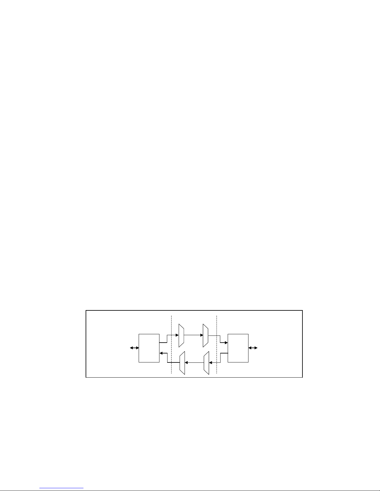
An SNMP managed network consists of three key components: Network Management Systems (NMS), agents, and
managed devices.
An NMS is the console through which the network administrator performs network management functions, such as
monitoring status (e.g. alarm states) and remote controlling, of a set of managed devices. One or more NMSs must
exist on any managed network. Generally the NMS is a computer running third party SNMP control software. There
are a number of third party SNMP software applications currently available on the market.
An NMS polls, or communicates with, an agent. An agent is a network management software module that resides in
a managed device. An agent has local knowledge of management information and translates that information into a
form compatible with SNMP. The agent, therefore, acts as an interface between the NMS and the managed devices.
The NMS sends a request message, and control commands for the managed devices, to the agent, which in turn sends
a response message, containing information about the managed devices, back to the NMS.
A managed device contains an SNMP agent and resides on a managed network. Managed devices collect and store
management information and make this information available to NMSs using SNMP.
Managed device agent variables are organised in a tree structure known as a Management Information Base (MIB).
Within the MIB are parameters pertaining to the managed device. An Object Identifier (OID) number within the MIB
defines the managed device type. This is a unique number specific to the model of managed device. Other
information relating to the device is also stored, information such as alarm states, controllable settings, etc. The MIB
tree is organised in such a way that there will be no two MIB files with conflicting placements.
Normally an NMS polls an agent for information relating to the MIB in a managed device to be sent back to the
NMS. When certain conditions are met within the MIB, such as major alarm conditions, for example, the agent
automatically sends what is known as a trap to the NMS without any prompting from the NMS. This allows automatic
notification of a predetermined event.
NMS
NMS
IP
Network
MIB
SNMP Agent
Protocol Engine SNMP Agent
MIB
SNMP Agent
Protocol Engine SNMP Agent
MIB
SNMP Agent
Protocol Engine SNMP Agent
SNMP Block Diagram

4550-mem.ib.rev0.doc Page 11 of 13 27/07/2006
SNMP with IRT Products:
IRT Electronics currently employs SNMPv1 with its 4000 series frame. The frame acts as an agent when fitted with
a CDM-4000 module. This module has its own designated slot next to the power supply so as to not affect the
number of modules that the frame will take. Communication between the NMS, the frame and its loaded modules are
via this CDM-4000 module. Note that the NMS software is third party and not supplied by IRT Electronics.
Ethernet connection for SNMP operation is via an RJ45 connector on the rear of the frame, below the mains inlet.
Ethernet rate runs at either 10 baseT or 100 baseT.
Frame parameters, such as Name, Address and Location, are set via an RS232 interface, a D9 connector on the rear
of the frame below the mains inlet. A software terminal emulator, such as Tera Term or HyperTerminal, is used for
setting and reading the parameters of the frame.
IRT modules that are SNMP compatible need a plug-in SMU-4000 module with a program relevant to the module
that it is plugged into. Depending on the module, besides the module identification, parameters such as alarm states,
inputs and controls etc. are communicated to the CDM-4000 agent via a data bus on the rear of the frame. Thus the
CDM-4000 collects information on what is loaded within the frame, what positions they occupy, and their current
status for communication to the NMS when the NMS sends a request for information.
In the event of a major alarm from any of the SNMP compatible modules, or power supplies, a trap is automatically
sent by the CDM-4000 agent to the NMS without any prompting by the NMS. This alerts the operator to any fault
conditions that may exist that need immediate attention.
FRU-4000
FRAME
110/240 V 50/60 Hz
0.7 A (max.)
FUSES
110/120 Vac
1A S.B.
220/240 Vac
500 mA S.B.
AS3260 approval no.: CS6346N
Ass. no.: 804692
+-
48Vdc
Alarm
RS232
Ethernet
IRT SNMP Connections
IRT modules fitted
with SMU-4000 PSU’s
CDM-4000
IRT 4000 Series
IRT 4000 Series
IRT modules fitted
with SMU-4000 PSU’s
CDM-4000
Network Ethernet Cable
Ethernet Cable
Ethernet Cable
NMS
IRT 4000 Series SNMP Setu
p

4550-mem.ib.rev0.doc Page 12 of 13 27/07/2006
MEM-4550 SNMP Functions:
With the MEM-4550 installed in an IRT 4000 series frame with SNMP capability, the MEM-4550 can be
interrogated by an SNMP Network Management System (NMS).
The following SNMP functions are capable of being monitored by an NMS:
An indication of the current state of the Major and Minor Alarms;
An indication that the ASI signal is present;
An indication of the ASI data rate received on the ASI input;
An indication if there is an error within the ASI input;
An indication of the size of the ASI packets being received on the ASI input;
An indication that a link has been established on the Ethernet port;
An indication of which of the two available speeds that the Ethernet port is operating, 10 or 100;
An indication if the Ethernet port is in full or half duplex operation;
An indication of activity on the Ethernet port;
An indication if remote setting by SNMP is allowed for the operating parameters;
An indication of the Program Number that is being used for the ASI streams;
An indication of what the ASI payload rate has been set to;
An indication that the Ethernet port has been configured for Auto, 10Mb/100Mb or half/full rate;
An indication of the firmware version of the FPGA;
Trap automatically sent, if enabled, when an Urgent Alarm occurs or is cleared;
Unit reset control.

4550-mem.ib.rev0.doc Page 13 of 13 27/07/2006
Maintenance & storage
Maintenance:
No regular maintenance is required.
Care however should be taken to ensure that all connectors are kept clean and free from contamination of any kind.
This is especially important in fibre optic equipment where cleanliness of optical connections is critical to
performance.
Storage:
If the equipment is not to be used for an extended period, it is recommended the whole unit be placed in a sealed
plastic bag to prevent dust contamination. In areas of high humidity a suitably sized bag of silica gel should be
included to deter corrosion.
Where individual circuit cards are stored, they should be placed in antistatic bags. Proper antistatic procedures
should be followed when inserting or removing cards from these bags.
Warranty & Service
Equipment is covered by a limited warranty period of three years from date of first delivery unless contrary
conditions apply under a particular contract of supply. For situations when “No Fault Found” for repairs, a
minimum charge of 1 hour’s labour, at IRT’s current labour charge rate, will apply, whether the equipment is within
the warranty period or not.
Equipment warranty is limited to faults attributable to defects in original design or manufacture. Warranty on
components shall be extended by IRT only to the extent obtainable from the component supplier.
Equipment return:
Before arranging service, ensure that the fault is in the unit to be serviced and not in associated equipment. If
possible, confirm this by substitution.
Before returning equipment contact should be made with IRT or your local agent to determine whether the
equipment can be serviced in the field or should be returned for repair.
The equipment should be properly packed for return observing antistatic procedures.
The following information should accompany the unit to be returned:
1. A fault report should be included indicating the nature of the fault
2. The operating conditions under which the fault initially occurred.
3. Any additional information, which may be of assistance in fault location and remedy.
4. A contact name and telephone and fax numbers.
5. Details of payment method for items not covered by warranty.
6. Full return address.
7. For situations when “No Fault Found” for repairs, a minimum charge of 1 hour’s labour will apply,
whether the equipment is within the warranty period or not. Contact IRT for current hourly rate.
Please note that all freight charges are the responsibility of the customer.
The equipment should be returned to the agent who originally supplied the equipment or, where this is not
possible, to IRT direct as follows.
Equipment Service
IRT Electronics Pty Ltd
26 Hotham Parade
ARTARMON
N.S.W. 2064
AUSTRALIA
Phone: 61 2 9439 3744 Fax: 61 2 9439 7439
Table of contents
Other IRT Adapter manuals