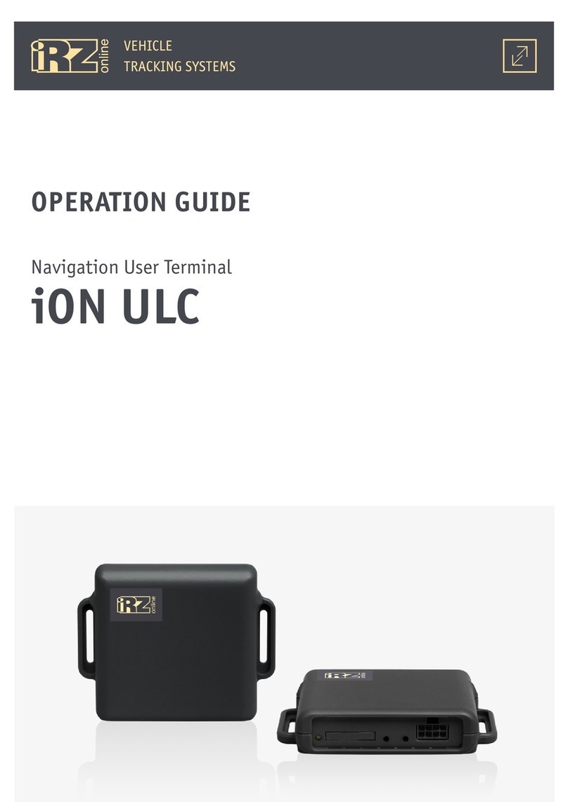
iRZ ion fm User manual

Navigation User Terminals
iON FM, iON Connect
CONFIGURAION COMMANDS
REFERENCE GUIDE

22
Table of Contents
1. INTRODUCTION ................................................................................................................... 5
2. WORKING WITH COMMANDS .................................................................................................. 6
2.1. Command format ............................................................................................................... 6
2.2. Entering password when sending commands ........................................................................... 7
2.3. Methods of command sending .............................................................................................. 7
3. LIST OF COMMANDS ............................................................................................................ 10
3.1. Access by security password ................................................................................................10
PASS — Security password input
CPWD — Changing security password
3.2. Operating modes...............................................................................................................12
PW#MODE — Operating mode selection
PW#TW1 — Setting timeout for switching to mode 1
PW#TW2 — Setting timeout for switching to mode 2
PW#TS1 — Setting timeout for waking up in mode 1
PW#TS2 — Setting timeout for waking up in mode 2
PW#EN1 — Allowing or denying mode 1
PW#EN2 — Allowing or denying mode 2
3.3. GSM connection ................................................................................................................15
GSM#D — Reading diagnostic data from GSM module
GSM#1#LOCK — Allowing and denying PIN code entering
GSM#1#PIN — Configuring PIN code
GSM#1#ROAM — Denying and allowing roaming
GSM#1#SCID — Reading of SIM card’s SCID
GSM#IMEI — Reading of IMEI number
3.4. GPRS internet ...................................................................................................................18
APN#1#MODE — Selecting SIM card’s operating mode
APN#1#NAME — Configuring SIM card’s APN address
APN#1#USER — Configuring SIM card’s APN user
APN#1#PSW — Configuring SIM card’s APN password

33
3.5. GPS coordinates ................................................................................................................20
GPS#D — Reading diagnostic data from GPS module
GPS#F1 — Exceeding steering angle
GPS#F2 — Exceeding distance
GPS#F3 — Filter track points by “movement sensor“
GPS#F4 — Track point filter by “Speed”
GPS#T1 — Track point save period
RT#T1 — Real-time point transmission period
LOCATION — Obtaining GPS coordinates via SMS
3.6. Web monitoring server .......................................................................................................25
SRV#1 — Configuration of IP/DNS address of processing server
DGROUP — Data grouping mode
3.7. Movement Sensor ..............................................................................................................26
MOVE#ST — Reading current status of movement sensor
MOVE#F1 — Configuring passivity of motion sensor
MOVE#F2 — Configuring sensitivity of motion sensor
3.8. Inputs ............................................................................................................................30
IN#1#TP, ... — Selecting multipurpose input
IN#T — Configuration of period of data reading from multipurpose inputs
IN#1#PULL, ... — Configuration of resistor pull-up on multipurpose input
IN#1#HI, ... — Configuration of logic 1 level on multipurpose input
IN#1#LO, ... — Configuration of logic 0 level on multipurpose input
IN#1#CLR, ... — Resetting pulse counter
IN#IMP — Reading data at pulse input
IN#AVER — Reading data at analog input
IN#FREQ — Reading data at frequency input
IN#LOG — Reading data at logic input
IN#F1 — Track point filter from inputs “by value change”
3.9. Outputs ...........................................................................................................................33
OUT#5, ... — Switching status at control outputs
3.10. RS485 interface ..............................................................................................................34
485#1#TP, ... — Allowing and denying data reading from liquid level sensors
485#1#A, ... — Configuration of network address for liquid level sensors
485#SPEED — Configuration of data rate with liquid level sensors
485#T — Configuring period of data reading from liquid level sensors

4
485#1#D, ... — Reading of measurements from liquid level sensors
485#1#M — Setting operating mode for RS485
3.11. CAN-LOG ........................................................................................................................38
CAN-L — Rebooting CAN-LOG
CAN-L#DA — Reading of current software version for CAN-LOG
CAN-L#PROG — Setting CAN-LOG program number
3.12. Driving style ...................................................................................................................39
DS#BRAKE — Warning of breaking overload
DS#TURN — Warning of overload at turn entry
DS#G_SHAKE — Warning of overload at impacts
DS#W_SHAKE — Warning of overload during shaking
DS#ACC — Warning of acceleration overload
DS#INIT — Resetting user driving style warning settings
3.13. Buzzer ...........................................................................................................................41
BUZ#MODE — Buzzer operating mode
SPD#LVL — Setting speed threshold for buzzer signal
DS#BUZ — Buzzer signal on driving style violations
3.14. Vehicle safety .................................................................................................................42
EMRG#MODE — Operation mode of alerts of vehicle safety
TEL#EVAC — Telephone number for alerts of vehicle evacuation
TEL#EMRG — Telephone number for alerts of road accident
MOVE#TO — Configuration of parking event registration time
VIGN — Configuration of voltage ignition “ON”
3.14. Device operation information ............................................................................................45
VER — Read software version information
VIN — Read current value of external voltage
VBAT — Read current value of battery’s voltage
TMP#1#T — Read temperature value
3.15. System commands ...........................................................................................................47
RESET — Reset operating system
CFG#RESET — Reset to factory settings
ETRACK — Clear black box memory
ALPHABETIC LIST OF COMMANDS ............................................................................................. 48

5
1. Introduction
This document contains a list of commands for configuration of iON FM, iON Connect user terminals.
Version Date Prepared by: Revisions
1.0 22.06.2016 D. N. Konev, V. N.
Golovin
Main document
1.0.1 01.08.2016 V. N. Golovin Changed description: SRV#1
1.0.3 01.09.2016 V. N. Golovin Changes: RT#T1 (3.5), 2.2
1.1 12.09.2016 V. N. Golovin Changes: deleted unsupported command GSM#1#TEL, edited SRV#1
1.1.1 26.09.2016 V. N. Golovin Changes: IN#1#TP
1.2 01.11.2016 V. N. Golovin Changes: added new commands — GPS#F4, DGROUP, IN#F1, EMRG#MODE,
TEL#EVAC, TEL#EMRG, MOVE#TO, VIGN, edited commands — GPS#F3,
BUZ#MODE, SPD#LVL, DS#BUZ
1.2.1 03.11.2016 V. N. Golovin Changes: edited parameters of MOVE#TO command
1.2.2 20.12.2016 V. N. Golovin Changes: edited parameters of DS#BRAKE, DS#TURN, DS#G_SHAKE,
DS#W_SHAKE, DS#ACC commands
1.2.3 06.04.2017 V. N. Golovin Changes: added parameters of DGROUP
1.2.4 05.07.2017 V. N. Golovin Changes: iON Connect CAN support removed
1.3 10.07.2017 V. N. Golovin Changes: descriptions of PW#TS1, PW#TS2

6
2. Working with commands
2.1. Command format
The format is similar to AT modem’s commands syntax.
Requesting current parameter value.
To receive current parameter value, enter the command and “?” after “=” in the following format:
COMMAND=?
Example:
GSM#1#LOCK=?
Reply example:
GSM#1#LOCK=?
GSM#1#LOCK=0
OK
Changing parameter value.
To save parameter value, enter the command and the new value after “=” in the following format:
COMMAND=Х , where Х — is a numeric or a text value.
Example:
OUT#6=1
Reply example:
OUT#6=1
OK
Deleting parameter value.
To delete string parameter value, enter the command, followed by the word NULL after “=”:
COMMAND=NULL
Example:
APN#1#NAME=NULL
Reply example:
APN#1#NAME=NULL
OK

7
There are 3 types of commands:
1 only display parameter value or debug data only one parameter: ?
2 change parameter value set of parameters (including ?)
3 launch a function in the device with no set parameters
Command ends with a special symbol. Command end symbol depends on the interface receiving it.
For SMS commands it is separator “;”.
Web server and COM port commands use newline character [Enter] as a separator: 0x0d 0x0A.
Commands can be contained in one message, provided they are separated with command end symbol.
The device processes commands consecutively, one after another.
2.2. Entering password when sending commands
Access to device settings requires a password. By default, it is set to: 123456.
When entering password on a terminal during USB connection, it will be valid throughout the entire ses-
sion.
When changing settings via SMS, the password is required for each message. The password must be in the
beginning of the message, before the command or a group of commands.
SMS password must be entered in the following format: PASS=<password>;<command>=<parameter>;
An example of sending command via SMS:
PASS=123456;OUT#6=1;
2.3. Methods of command sending
Web interface.
In iRZ Online interface select “Settings” ►, “List of vehicles”, and select vehicle to which the device is
linked to from the list. Go to “ Edit” ► “Devices”.

8
Click “ Send command”, to open command dialog:
Enter the command;
Click “Send command”;
Response to the command will be displayed in the table.
Configuration tool.
Connect the device to a PC and launch Conf_iRZ configuration tool. Go to “Service” tab and open
access to the device (if required) by pressing “Unlock” button and entering security password (123456 by
default).
To send the command:
Enter the command;
Click “Send”;
Response will be displayed in a new window.

9
SMS message.
Format PASS=<password>;<command>=<parameter>; is supported when sending commands via SMS,
where:
●<password> is a security password for device configuration (123456 by default);
●<command> is a command to be executed;
●<parameter> is the command’s parameter (text and/or numerical value).
To send the command:
Enter phone number of the device’s SIM card;
Enter a command;
Send SMS message;
Response will come in SMS message, containing results of the command’s execution.

10
3. List of Commands
3.1. Access by security password
Command Description Possible values
PASS Entering security password
PASS command is designated for changing current security pass-
word for gaining full access to the device. Both of the connection
types (USB cable and GSM/SMS connection) require the password.
If the password was not entered, access to the device is not com-
plete and configuration changing is unavailable. However, current
values of the settings can always be read, for example: MOVE#ST=?
Entering the password gives access to device configuration com-
mands, which allow changing the existing values and specifying
new ones. The device cannot be reconfigured without the password.
Examples:
●Command for entering current security password:
PASS=123456 .
Recommendations:
●the devices are implemented with sessional mechanism of
password access, which means that it is required to enter secu-
rity password only once. After that, all of the commands may be
used without repeatedly entering the password. However, in the
case of reading and managing data via SMS, the password must
be entered in each of the messages;
●If the device is disconnected from the virtual COM port, (USB
cable) - physically or virtually - the session ends automatically.
It will be required to enter a password again during the next
connection of the device, if it is required to change current set-
tings as opposed to just reading them.
English characters and/or numbers
(123456 – default value).

11
Command Description Possible values
CPWD Changing the access password
CPWD command is designated for changing current security pass-
word, giving access to complete access to the device. The password
can be changed only via USB.
New password must contain from 4 to 11 characters. Admissible
characters: only English characters and/or numbers. Upper an lower
case letters are distinguished and are not considered identical.
Examples:
●command for setting new password: CPWD=123456,7777 ,
where 7777 is a new password, and 123456 is an old (current)
one.
Recommendations:
●security password is set to 123456 by default. There is no
way to reset the password. Thus, it is imperative that the user
does not loose the password once it was changed.
This command is not executed if received by SMS.
English characters and/or numbers

12
3.2. Operating modes
Command Description Possible values
PW#MODE Terminal operating modes selection
PW#MODE command is designated for reading the current value and
setting new value for the parameter responsible for selecting the
device’s current operation mode; determines power consumption
and power saving.
Examples:
●command for reading current value: PW#MODE=?;
●example of command for setting new value, the device will
be switched to “Main mode”: PW#MODE=0;
●command for setting new value, the device will be switched
to “Active mode”: PW#MODE=1.
? – reading of current value;
0 – “Main mode” (default value);
1 – “Active mode”;
2 – “Power saving mode” (Mode 1);
3 – “Sleep mode” (Mode 2).
PW#TW1 Setting timeout for switching to mode 1
PW#TW1 command is designated for reading the current value and
setting new value for timeout. After it expires, the device in quies-
cent state (vehicle not moving) will automatically switch to “Power
saving mode” (LPWR1). The value is measured in minutes (min.)
Maximal value is 1440 (min), i.e. 24 (h).
Examples:
●example of command for reading of current time value:
PW#TW1=?;
●example of the command for setting new time value of 1440
minutes: PW#TW1=1440.
Recommendations:
●it is imperative that PW#TW1 value is less than PW#TW2
value. Otherwise, it will not be accepted and error message will
be received.
? – reading of current value;
5 … 1440 minutes (60 by default for
iON FM).
PW#TW2 Setting timeout for switching to mode 2
PW#TW2 command is designated for reading the current value and
setting new value for timeout. After it expires, the device in quies-
cent state (vehicle not moving) will automatically switch to “Hi-
bernation mode” (LPWR2). The value is measured in minutes (min.)
Maximal possible value 1440 (min), i.e. 24 (h).
Examples:
●example of command for reading of current time value:
PW#TW2=?;
●example of the command for setting new time value of 1440
minutes: PW#TW2=1440;
Recommendations:
●it is imperative that PW#TW1 value is less than PW#TW2
value. Otherwise, it will not be accepted
? – reading of current value;
10 … 1440 minutes (720 by default
for iON FM).

13
Command Description Possible values
PW#TS1 Setting timeout for waking up in mode 1
PW#TS1 command is designated for reading the current value and
setting new value for timeout for waking. The device in “Power-
saving mode (Mode 1) will wake up at the set interval to send cur-
rent GPS/GLONASS (if positioning is available) or LBS coordinates,
and diagnostic data from the black box. The value is set in minutes
(min.) The default value is 60 minutes, maximal possible is 2880
(min), i.e. 48 (h).
Examples:
●example of command for reading of current time value:
PW#TS1=?;
●example of the command for setting new time value of 2880
minutes: PW#TS1=2880.
? – reading of current value;
5 ... 2880 – interval, min (60 – by
default for iON FM).
PW#TS2 Setting timeout for waking up in mode 2
PW#TS2 command is designated for reading the current value and
setting new value for timeout for waking. The device in “Deep Sleep
mode (Mode 2) will wake up at the set interval to determine and
instantly send current GPS/GLONASS (if positioning is available) or
LBS coordinates; no other data is transmitted. The value is mea-
sured in minutes (min.)
Maximal value is 5760 (min), i.e. 4 days.
Examples:
●example of command for reading of current time value:
PW#TS2=?;
●example of the command for setting new time value of 5760
minutes: PW#TS2=5760.
? – reading of current value;
10 ... 5760 – nterval, min (1440 –
by default for iON FM).
PW#EN1 Allowing and denying mode 1
PW#EN1 command is designated for reading the current value and
setting new value of the parameter responsible for allowing/deny-
ing the device to switch to “Power saving mode” (Mode 1).
Examples:
●example of command for reading current value: PW#EN1=?;
●command for allowing Mode 1: PW#EN1=1;
●command for denying Mode 1: PW#EN1=0.
Recommendations:
●please note, that denying automatic switching to Mode 1 or
2, the remaining mode will continue to perform according to its
settings.
? – reading of current value;
0 – mode denied;
1 – mode allowed (default setting).

14
Command Description Possible values
PW#EN2 Allowing and denying mode 2
PW#EN2 command is designated for reading the current value and
setting new value of the parameter responsible for allowing/deny-
ing the device to switch to “Sleep mode” (Mode 2).
Examples:
●example of command for reading current value: PW#EN2=?;
●command for allowing Mode 2: PW#EN2=1;
●command for denying Mode 2: PW#EN2=0.
Recommendations:
●please note, that denying automatic switching to Mode 1 or
2, the remaining mode will continue to perform according to its
settings.
? – reading of current value;
0 – mode denied;
1 – mode allowed (default setting).

15
3.3. GSM connection
Command Description Possible values
GSM#D Reading diagnostic data from GPS module
GSM#D command is designated for reading of current diagnostic
data from the device’s GSM module.
Examples:
●command for reading current value: GSM#D=?;
●possible response:
SIM=ok
ANT=ext
CSQ=23
REG=ok
OPS=25001
GPRS=down
SRV1=up
LPM=0
where:
SIM – SIM card status (1 – SIM1, 2 – SIM2):
●down – no data;
●ok – no errors detected;
●error,NONE – SIM card missing;
●error,ACCESS – PIN code required;
●error,PIN – SIM card does not accept PIN code;
●error,PUK – PUK code required;
ANT – antenna:
●ext – external;
●int – internal;
CSQ – signal level (0 to 31);
REG – network registration flag:
●ok – registered in home network;
●roaming – registered in roaming;
●error – registration failed;
●search – searching for network;
●disable – registration denied;
●down – module has not registered in the network;
OPS – network operator code;
GPRS – GPRS status:
●up – operational;
●down – not operational;
SRV1 – connection status:
●up – operational;
●down – not operational;
LPM – value of device’s current operation mode.
? – reading of current value

16
Command Description Possible values
GSM#1#LOCK Allowing and denying PIN code input
GSM#1#LOCK command is designated for reading the current value
and for setting new value for parameter which determines the ne-
cessity to enter PIN code. If set to obligatory PIN entry, then PIN
code must be set by command GSM#1#PIN in advance.
Examples:
●example of command for reading current value:
GSM#1#LOCK=?;
●example of command for setting new value: GSM#1#LOCK=1,
In this case the terminal will always attempt to enter PIN code
upon activation.
Recommendations:
●terminals are implemented with SIM lock protection mecha-
nism, so there is no chance for user to accidentally lock a SIM
card by entering an incorrect code. The device will not attempt
entering PIN code more than once. If SIM card informs the
device that wrong PIN number has been already entered 1 or 2
times, then the device will not attempt entering even a cor-
rect PIN code, until PIN attempt counter is reset. To reset the
counter, insert SIM card into mobile phone and manually enter
the correct PIN code;
●if required, check SIM card’s accessibility to the terminal by
accessing diagnostic data via GSM#D=? command.
? – reading of current value;
0 – PIN input disabled (default);
1 – PIN input enabled.
GSM#1#PIN PIN code configuration
GSM#1#PIN command is designated for reading the current value
and for setting new value for PIN code used by the device to access
a SIM card.
Examples:
●command for reading current value: GSM#1#PIN=?;
●example of command for setting new value:
GSM#1#PIN=1234.
Recommendations:
●if SIM card already has a set PIN code, then it is required to
give this code to the terminal beforehand via GSM#1#PIN com-
mand. Otherwise, it will attempt to use the default PIN setting:
0000;
●reading SIM card’s PIN by GSM#1#PIN=? command is impos-
sible. It only reads the value that was set by user to be used by
the terminal;
●GSM#1#PIN command must be used in conjunction with
command GSM#1#LOCK.
? – reading of current value;
0000 ... 9999 – PIN code (0000 by
default).

17
Command Description Possible values
GSM#1#ROAM Allowing and denying roaming
GSM#1#ROAM command is designated for reading the current value
and for setting new value for parameter responsible for allowing/
denying transmission of GPRS/GSM data in roaming.
Examples:
●command for reading current value: GSM#1#ROAM=?;
●example of command for setting new value: GSM#1#ROAM=1.
Recommendations:
●if a vehicle (terminal) enters roaming, then (in case roam-
ing operation is denied) the data will stop being transmitted
to monitoring server. This will decrease expense of a SIM card’s
funds;
●to transmit data in roaming, make sure the function is al-
lowed (it is disabled by default).
? – reading of current value;
0 – denied (default);
1 – allowed.
GSM#1#SCID Reading SIM card’s SCID
GSM#1#SCID command is designated for reading SCID value of the
device’s SIM card.
Examples:
●command for reading current value: GSM#1#SCID=?.
Recommendations:
●the command is used to restore information about SIM card,
installed in the device. SCID and phone number of SIM card are
provided by the mobile operator and can be found in documen-
tation and on the card itself.
? – reading of current value
GSM#IMEI Reading of IMEI number
GSM#IMEI command is designated fore reading IMEI of the termi-
nal’s GSM module.
Examples:
●command for reading current value: GSM#IMEI=?.
Recommendations:
●IMEI number can be used when connecting the terminal to
an alternative monitoring server or when contacting iRZ Online
technical support.
? – reading of current value

18
3.4. GPRS Internet
Command Description Possible values
APN#1#MODE SIM card operating mode selection
APN#1#MODE command is designated for reading the current value
and for setting new value for a parameter determining SIM card’s
APN mode.
Examples:
●example of command for reading of current value of APN
mode: APN#1#MODE=?;
●example of command for setting new APN mode value:
APN#1#MODE=1 . The command instructs the terminal to use
SIM card configuration, set by a user.
Recommendations:
●if the terminal does not establish internet connection to
the monitoring server, it can be caused by GSM module failing
to receive automatic GPRS settings from the mobile operator.
In this case, it must be configured manually via APN#1#USER,
APN#1#PSW, APN#1#NAME commands. Activate them by
APN#1#MODE=1 command.
? – reading of current value;
0 – “Automatic mode”, i.e. automatic
SIM configuration (default);
1 – “User mode” i.e. using custom
SIM settings.
APN#1#NAME Configuring SIM card’s APN address
APN#1#NAME command is designated for reading the current value
and for setting new value for SIM card’s APN address. The value may
vary depending on the GSM mobile operator.
Examples:
●example of command for reading of current value of APN ad-
dress: APN#1#NAME=?;
●example of command for setting new APN address value:
APN#1#NAME=internet.mts.ru.
Recommendations:
●the device contains stored values for 3 most popular Russian
mobile network operators (Beeline, MTS, Megafon) respectively:
internet.beeline.ru, internet.mts.ru, internet;
●please note, that this setting will be used only if the corre-
sponding mode has been activated by command APN#1#MODE.
? – reading of current value;
english letters and/or numbers
(NULL by default).

19
Command Description Possible values
APN#1#USER Configuring SIM card’s APN user
APN#1#USER command is designated for reading the current value
and for setting new value (name) for the SIM card’s APN user. The
value may vary depending on the GSM mobile operator.
Examples:
●example of command for reading of current value of APN
user: APN#1#USER=?;
●example of command for setting new APN user value:
APN#1#USER=mts;
Recommendations:
●the device contains stored values for 3 most popular Russian
mobile network operators (Beeline, MTS, Megafon) respectively:
beeline, mts, gdata;
●please note, that this setting will be used only if the corre-
sponding mode has been activated by command APN#1#MODE.
? – reading of current value;
english letters and/or numbers
(NULL by default).
APN#1#PSW Configuring SIM card’s APN password
APN#1#PSW command is designated for reading the current value
and for setting new value for SIM card’s APN password. The value
may vary depending on the GSM mobile operator.
Examples:
●example of command for reading of current value of APN
password: APN#1#PSW=?;
●example of command for setting new APN password value:
APN#1#PSW=mts.
Recommendations:
●the device contains stored values for 3 most popular Russian
mobile network operators (Beeline, MTS, Megafon) respectively:
beeline, mts, gdata;
●please note, that this setting will be used only if the corre-
sponding mode has been activated by command APN#1#MODE.
? – reading of current value;
english letters and/or numbers
(NULL by default).

20
3.5. GPS coordinates
Command Description Possible values
GPS#D Reading diagnostic data from GPS module
GPS#D command is designated for reading of current diagnostic
data from the device’s GPS module.
Examples:
●example of command for reading of current value of diagnos-
tic data: GPS#D=?;
●a possible response for iON FM terminal:
ANT=ext
VAL=1
HDOP=0.8
TIME=20/10/2015 09:00:59
LAT=60.031624,S
LON=030.403304,W
CURS=130.26
SPEED=0.42
SAT=9
LPM=0
MODE=’00h’
where:
ANT – antenna:
●ext – external;
●int – internal;
VAL – values:
●1 – reliable;
●0 – unreliable;
HDOP – signal quality;
TIME – date and time;
LAT – latitude (N/S);
LON – longitude (E/W);
CURS – course in degrees;
SPEED – speed in knots;
SAT – number of detected satellites;
LPM – value of device’s current operation mode.
? – reading of current value
Other manuals for ion fm
1
This manual suits for next models
1
Table of contents
Other iRZ Car Navigation System manuals
Popular Car Navigation System manuals by other brands

Subaru
Subaru 2014 BRZ Quick reference guide

Hyundai
Hyundai TUSON owner's manual

VAG-Navisystems
VAG-Navisystems Navegador Multimedia NaviTOUCH Installation and configuration manual

Volvo
Volvo SENSUS NAVIGATION WEB EDITION manual

Magellan
Magellan RoadMate 9600-LM user manual

TomTom
TomTom BRIDGE reference guide

Rand McNally
Rand McNally Intelliroute TND-710 quick start guide

Pioneer
Pioneer AVIC-EVO1-DT2-C-GR installation manual

Peterbilt
Peterbilt PACCAR Operator's manual

Navman
Navman iCN 630 brochure

BrandMotionotion
BrandMotionotion ADAS+ Manual guide

Sanyo
Sanyo NV-E7000 - Portable GPS And Mobile DVD Entertainment... Service manual