ISIC PCM4-H77 User manual

PCM4 manual
H77 version

Disclaimer
ISIC A/S makes no representation or warranties with respect to the contents or use of this
manual, and specifically disclaims any express or implied warranties of merchantability or
fitness for any particular purpose. Further, ISIC A/S reserves the right to revise this
publication and to make changes to its content at any time, without obligation to notify any
person or entity of such revisions or changes.
FCC Warning
Computing devices and peripherals generate, use, and can radiate radio frequency energy, and
if not installed and used in accordance with the instructions advised by ISIC A/S, may cause
interference to radio communication.
The PCM4 series of PC’s, manufactured by ISIC A/S, is designed to comply with the emerging
generic EEC standards, that cover applications in maritime environment.
Classification
The PC is classified as Environmental condition “protected” acc. to EN60945 ed. 4
Approvals
Approval according to EN60945 ed. 4; Maritime navigation and radio communication
equipment and systems – General requirements.
ISIC A/S is complying with the WEEE directive within the European Union, stating that
electronic and electric products must be collected separately.
Products are marked according to the directive
Copyright 2013 ISIC A/S
ISIC P/N: 05902-000 Rev A
ISIC A/S
Edwin Rahrs Vej 54
DK-8220 Brabrand
Denmark
Phone: +45 70 20 70 77
Fax: +45 70 20 79 76
Web: http://www.isic-systems.com
User Reference Manual, P/N:05902-000 Rev A Page 2

ISIC PCM4 User Manual
Congratulations on your purchase of ISIC PCM4. This short form manual is designed to get you
started working with your new PCM4. It is not meant to cover all possible options or situations.
For a more detailed description of the PCM4 motherboard, please read the fully comprehensive
Main Board Manual obtainable on the CDROM.
Package contents:
1 PCM4
1 CDROM containing PCM4 Manual and Main Board Manual (optional)
1 Power cable (optional)
If any of these items are not present, please contact ISIC.
User Reference Manual, P/N:05902-000 Rev A Page 3

Table of Contents
1GENERAL CONSIDERATIONS ON INSTALLATION AND OPERATION ............................................................5
2GETTING STARTED ...................................................................................................................................................5
3PCM4 H77 OVERVIEW............................................................................................................................................6
4MOTHERBOARD CONNECTION OVERVIEW......................................................................................................7
5INSTALLING ADDITIONAL EXPANSION CARDS ................................................................................................8
6TECHNICAL SPECIFICATIONS...............................................................................................................................9
7MECHANICAL DIMENSIONS...............................................................................................................................10
8MOUNTING POSITIONS........................................................................................................................................12
9PCM4 SYSTEM INDICATORS................................................................................................................................12
10TROUBLESHOOTING..........................................................................................................................................13
11SERVICING THE UNIT ........................................................................................................................................13
12GENERAL NOTES ON USB................................................................................................................................13
13ISIC INFO / SUPPORT........................................................................................................................................14
14REVISION HISTORY............................................................................................................................................15
User Reference Manual, P/N:05902-000 Rev A Page 4

1General considerations on Installation and
Operation
The PCM4-H77 is designed to work at conditions according to IEC 60945. However, keeping the
temperature and vibration level at a minimum will extend the life time of the product. ISIC
recommend operating this product at normal room temperature (20-25 °C), with the lowest level of
vibration and humidity.
Installation of the PCM4-H77
When designing the cabinet/console for the PCM4-H77, please ensure that air can flow freely
around the cabinet, in order to avoid any unnecessary rise in temperature. If it is not possible to
have an adequate natural airflow, use a fan to force the airflow to be higher.
2Getting started
Please refer to the PCM4 overview for location of connectors specified in this section.
Connect Keyboard/Mouse to the connector specified in PCM4 overview or connect to the USB
connectors.
Connect the monitor to the DVI, HDMI or DisplayPort connector.
Connect all other needed connectors ending with the Power outlet.
Press the ON/OFF button to “I” position.
To power up the PCM4, you need to press the power button (dependant on BIOS setting). Use
a pencil or similar for that purpose. If the temperature is very cold (below approx. 1.5°C) and
the PCM4 has the special ISIC HPC option (Heater Power Controller) the PCM4 will
automatically begin warming the components inside. That process can take up to 30 minutes.
During that process, the power LED will flash red to indicate the warming process. When the
PCM4 has reached the sufficient temperature, it will automatically start to boot.
Please refer to PCM4 system indicators on page 11 for an in-depth description.
The PCM4 will be in standby mode when you power down. To restart the PCM4 again, use a
pencil on the power button.
User Reference Manual, P/N:05902-000 Rev A Page 5

3PCM4 H77 overview
Front view PCM4-H77
Rear view PCM4-H77
Power ac See Motherboard Connection Overview
(next page)
Power DC:
+ : 24V DC
- : 0V
: Chassis
User Reference Manual, P/N:05902-000 Rev A Page 6

4Motherboard connection overview
Below is an overview of motherboard connections and pin-out of the same.
User Reference Manual, P/N:05902-000 Rev A Page 7

5Installing additional expansion cards
Always disconnect the Power outlet before removing the top cover.
Remove the 9 overhead screws and top cover.
Remove the slot screw and remove the blind bracket. Install the add-on card in the slot and
then replace the slot screw. Replace the top cover and the 9 overhead screws.
PCM4-H77 motherboard
Blind bracket
PCIe x 16 PCIe x 1
PCIe x 1 3 times PCI
Slot screw
ATTENTION - This marine computer is covered by ISIC warranty, and any alterations
may render marine certificate and warranty invalid
User Reference Manual, P/N:05902-000 Rev A Page 8

6Technical specifications
PCM4-H77 - General
CPU: Core™ i3-3220 (2 Cores, 4 Threads)
Optional Core™ i7-3770 (4C/8T)
Chipset: Intel® H77 Express
64Bits, Hyper-Threading and Virtualization Technology with Enhanced
SpeedStep® and Turbo Boost Technology
5GT/s Direct Media Interface
Memory: 1 GB DDR3 RAM 1066 MHz (Standard)
Optional Upgrades
4 DIMM sockets supporting up to a total of 16GB DDR3 1066/1333/1600 RAM
Video: On-CPU Intel HD Graphics 2500 (Core i3) / 4000 (Core i7)
The maximum supported resolution is 1900 x 1200 (WUXGA)
DirectX 10.1 and OpenGL 3.0 compliant
DirectX 11.0 CS4.0 only / Shader model 4.0
Dual independent display support
Optional PCIe x16 graphics card
Audio: 10-channel (7.1 + 2) Intel High Definition Audio (Realtek ALC892 audio
Codec)
Ethernet: 10/100/1000 Mbit/sec Ethernet (RJ45) – onboard
Hard Disk Drive: 100+GB 2.5”, SATA (Standard)
Optional Upgrades
Sizes up till 500GB, 24/7 rated disk, 2.5” SATA
Solid State Disc 32,64,128 GB
5¼” drive bay: DVD-R/W Drive (SATA interface)
Optional Combined Removable Solid State disk drive and Slide-in DVD drive
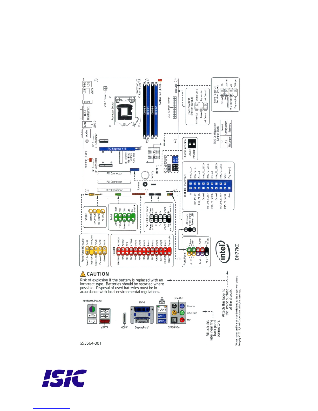
PCM4-H77 - Ports
Video: HDMI+DVI-I + DisplayPort video out
Audio: 5x 3.5mm jack socket, Optical S/PDIF out
Ethernet: 1x RJ45
Serial: Optional 1 x RS232 un-isolated. Routed to back from Motherboard header.
USB: 4x USB 3.0 ports (2 on back and 2 on internal header)
10x USB 2.0 ports (4 on back, 2 on internal header, 2 via Mini PCIe and 2
accessible from front)
SATA: RAID 0,1,5,10 supported by onboard Intel Rapid Storage Technology
2x 6.0Gb/s, 3x 3.0Gb/s (1 port shared with mSATA on Mini PCIe)
eSATA: 1x eSATA 3.0Gb/s (on back)
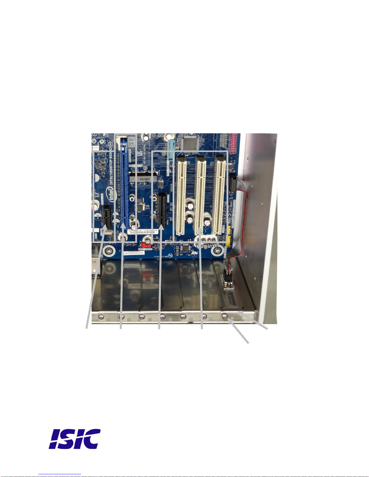
Expansion Slots: 1x PCI Express x16, 1x PCI Express x4, 1x PCI Express x1, 3x PCI
1x PCI Express Full-/Half-Mini Card slot with support for mSATA
PCM4-H77 – power
Standard: 90-264 VAC, 50-60 Hz, 300 Watt
Automotive: 18-36 VDC
PCM4-H77 – Environmental
Operating Temperature: -15 to 55 °C
Storage Temperature: -25 to 70 °C
Relative Humidity: 8 to 90 %
PCM4-H77 - Approvals
CE Mark: EN61000-6-2 & EN61000-6-4
Marine:
Type Approvals: IACS E10 rev. 5 & IEC 60945 Ed. 4
For latest marine class approvals – see www.isic-systems.com
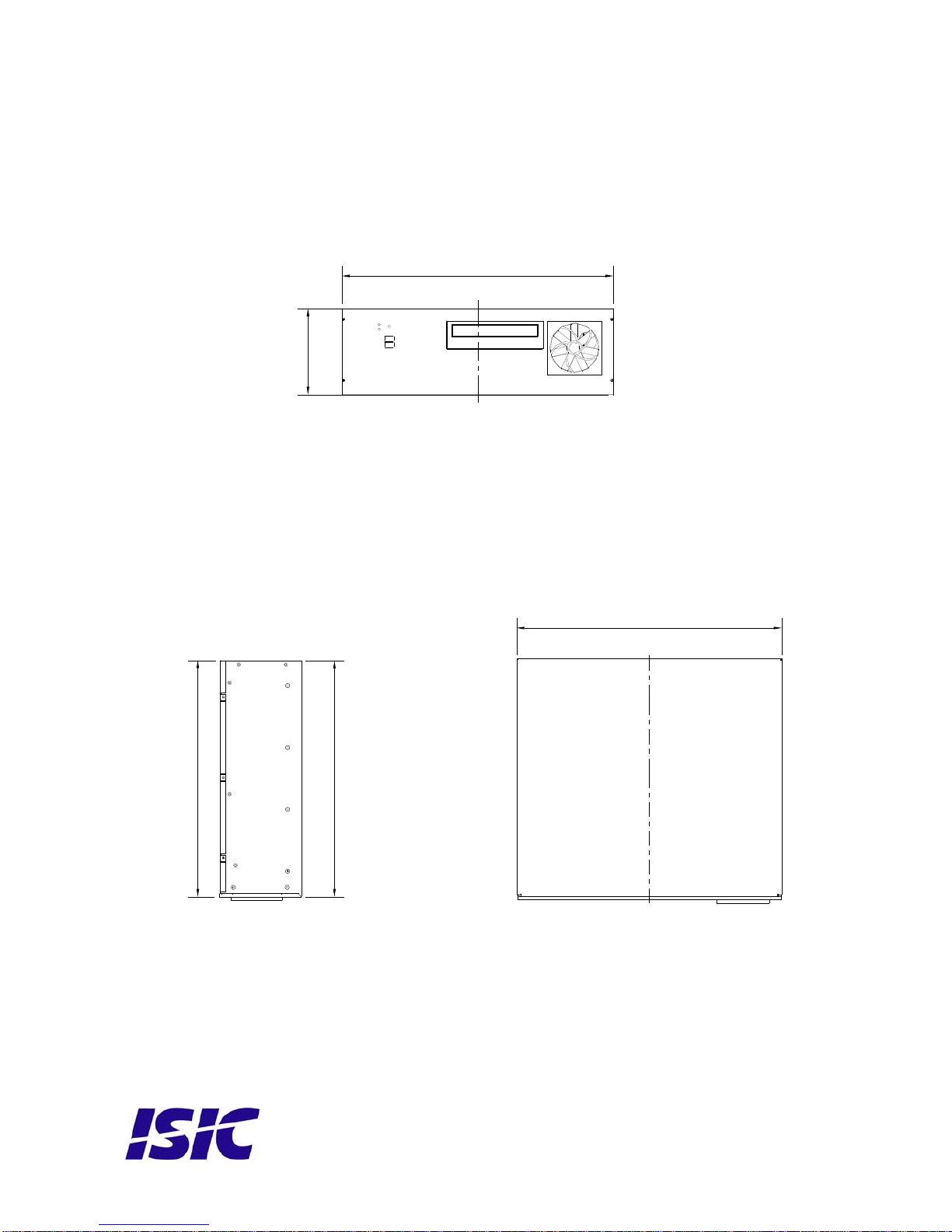
PCM4-H77 - Dimensions
Basic Version: 420 x 132 (3U) x 380 mm
Brackets: Mounting-angles - Optional 19” brackets for 19” rack-mount (on shelf)
Weight: 11 Kg
User Reference Manual, P/N:05902-000 Rev A Page 9

User Reference Manual, P/N:05902-000 Rev A Page 10
7Mechanical dimensions
132,5
418
381
Cover = 381,8
Cover = 420,5

User Reference Manual, P/N:05902-000 Rev A Page 11
Cabinet with 19” brackets and rails.
462,5 3,53,5
37,7 57,2
482,6 = 19''
6,8
132,5
32031
420,5
478
458
66 250
4 piece ø8
381

User Reference Manual, P/N:05902-000 Rev A Page 12
8Mounting positions
The PCM4 can be mounted in horizontal and vertical positions, but NOT upside down.
If needed, it
9
The PCM4 is
Having a versio LED is used to
simply indicate if sk activity.
In a PCM4 to provide an
indication of th isk activity;
the upper LE
ED Indication Description
is also possible to mount the PCM4 with the DVD drive facing downwards.
PCM4 System Indicators
equipped with two LED’s, located on the case front.
n without the ISIC HPC option (Heater Power Control), the upper
the system is on or off, while the lower LED indicated Hard Di
having the ISIC HPC option the display capability has been extended
e current PCM4 system state. The lower LED still indicates Hard D
D has been reconfigured as described in the following table:
L
Off Power is removed from the system.
Red
Flashing Boot sequen
Drive is heat
1.25 Hz :
2.5 Hz :
5 Hz :
ce is delayed up to 30 minutes while the Hard Disk
ed.
HDD Temperature is below -5°C
HDD Temperature is between -5°C and +5°C
HDD Temperature is above +5°C
Green
Flashing The sy
State”
stem is monitored for 10 seconds to ensure valid boot-up.
If the motherboard shuts down as a consequence of BIOS “Last
settings, it will be forced to reboot.
Green System is on.
Red System is in standby mode.

User Reference Manual, P/N:05902-000 Rev A Page 13
10 Troubleshooting
Problem Cause Solutions
The PCM4 won’t start - There is no power - Connect the power cord
connected
- The ON/OFF button at th
rear side is in the ‘O’ posit
(ac version only)
e
ion - Push the ON/OFF button to
the ‘I’ position
- The power button on the
front has not been pressed - Use a
bu pencil on the power
tton
- USB power overload - Read paragraph “General
notes on USB”
The PCM4 starts, but there is - The display cable is not - Connect the display cable
no picture on the screen connected, or have fallen out
- The Power LED is flashing
green (HPC option only) - The temperature is low and
the PCM4 is warming up. This
process can take up to 30
minutes.
- Your brightness/contrast on
the monitor is either at max
or min level. to the correct levels.
- Turn the brightness/contrast
Servi
In case that the unit st the unit to ISIC for repair. There
ser serviceab
12 General notes on USB
In the USB specification a max power consumption of 500mA on each USB port is specified.
If you experience start up problems, start by removing all USB devices, and then try to restart
the PCM4 again.
Faulty USB devices can also cause malfunction of your PCM4.
11 cing the unit
ill fails after following the troubleshooting send
are no u le parts inside.

User Reference Manual, P/N:05902-000 Rev A Page 14
13 ISIC info / Support
In case you have inquiri
get support. es or probl N, you hav
ompany name: ISIC A/S
ead office: Edwin Ra
DK – 8220
Denmark
up
0 B
enmark
Telephone: +45 70 20
Fax: +45 70 20 79 76
ail: mail@isic-
ems with your DuraMO e a number of possibilities to
C
H
hrs Vej 54
Brabrand
Shipping address: Holmstr
DK-822
D
gaardvej 5
rabrand
70 77
Msystems.com
systems.comwww: www.isic-
VAT number: DK 16 70 45 39
IFT: HANDDKKK
AN for DKK: DK53 0892 0001 0159 69
AN for EUR: DK48 0892 0003 0026 19
Bank Name/Address: Handelsbanken A/S
Havneholmen 29
DK – 1561 København V
Denmark
nk Code: 0892Ba
SW
IB
IB
IBAN for USD: DK26 0892 0003 0026 27
ontacts:C
RFQ’s: By fax to +45 70 20 79 76
rders:O By fax to +45 70 20 79 76
Support: Via homepage www.isic-systems.com under aftersales
Service: Before shipment for service Request Return Material Authorisation number
at homepage www.isic-systems.com
During office-hours (Mo-Fr: CET 0800
under RMA

User Reference Manual, P/N:05902-000 Rev A Page 15
14 Revision history
Rev A Jan 2013 Release

Edwin Rahrs Vej 54
DK-8220 Brabrand
com
Email: service@isic-systems.com
Denmark
Web: http://www.isic-systems.
User Reference Manual, P/N:05902-000 Rev A Page 16
Table of contents