ITALIAN STAGE 2MIX3UB User manual

2MIX3UB
USB Interface Mixer
USER MANUAL
MANUALE D'USO
REV. 00/18


3
INDICE
INTRODUZIONE 4
PRECAUZIONI 5
PANNELLO DI CONTROLLO 7
CONNESSIONI 9
CONFIGURAZIONI 10
SPECIFICHE TECNICHE 17
CONFORMITÀ 18
INDEX
INTRODUCTION 4
PRECAUTIONS 11
CONTROL PANEL 13
CONNECTIONS 15
CONFIGURATIONS 16
TECHNICAL SPECIFICATIONS 17
CONFORMITY 18

4
INTRODUZIONE
Grazie per aver scelto il mixer ITALIAN STAGE 2MIX3UB.
Vi auguriamo grandi soddisfazioni nell'utilizzo dei mixer ITALIAN STAGE.
Si prega di leggere attentamente questo manuale prima dell'uso, in modo da poter sfruttare a pie-
no le caratteristiche di 2MIX3UB e mantenere i massimi livelli di sicurezza e performance negli anni
a venire.
Conservate questo manuale in un luogo sicuro ed asciutto, per potervi facilmente accedere.
INTRODUCTION
Thank you for your purchase of the ITALIAN STAGE 2MIX3UB.
We hope that you will enjoy the use of the ITALIAN STAGE mixer.
Please read carefully through this manual before beginning to use, so that you will be able to take
full advantage of the 2MIX3UB features and enjoy trouble-free operation for years to come.
Please keep this manual at a safe and dry place where you easily can access it.
I
T
A
L
I
A
N
O
ATTENZIONE
Prima di accendere il dispositivo leggere attentamente le istruzioni di sicurezza per
evitare incidenti o danneggiamenti del prodotto.
Manuale utente (italiano) -> a partire da pagina 5
E
N
G
L
I
S
H
CAUTION
Before switching on the instrument or device read carefully the safety instructions to
avoid serious injuries or damage of the product.
Operators manual (english) -> start from page 11

5
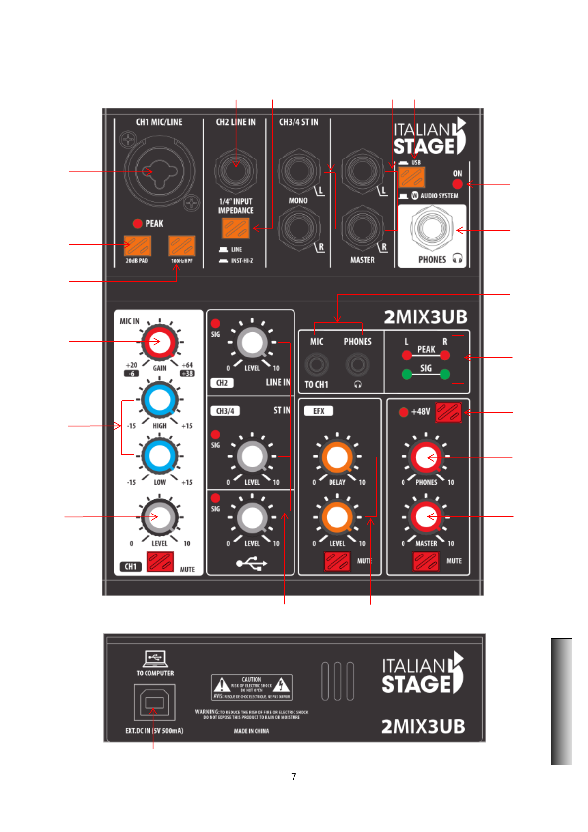
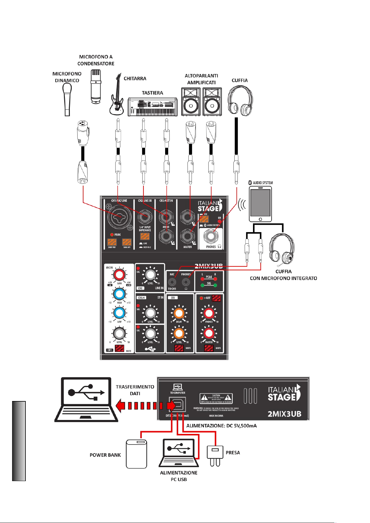
Manuale Utente 2MIX3UB
PRECAUZIONI
Si prega di leggere attentamente prima di procedere
Attenzione:
Seguite sempre le precauzioni di base elencate di seguito per evitare la possibilità di lesioni gravi o
addirittura di morte da: scosse elettriche, cortocircuiti, danni, incendi o altri pericoli. Queste pre-
cauzioni includono, ma non ne sono limitate, i seguenti punti:
Cavo di alimentazione (dispositivi con cavi di alimentazione):
• Utilizzare solo la tensione corretta specificata per il dispositivo. La tensione necessaria è indicata
sulla targhetta del dispositivo. Controllare il cavo di alimentazione di volta in volta per quanto ri-
guarda sporcizia, danni o altro.
• Utilizzare solo il cavo di alimentazione o l'adattatore incluso. Non posizionare il cavo di alimenta-
zione in prossimità di fonti di calore, quali: radiatori o caloriferi e non piegarlo eccessivamente, non
posizionare oggetti pesanti su di esso, non collocarlo in una posizione dove chiunque possa cam-
minarvi sopra, per evitare di danneggiare il cavo stesso.
• Togliere la spina dalla presa di corrente quando il dispositivo non viene utilizzato per lunghi pe-
riodi di tempo o durante i temporali. Quando rimuovete il cavo elettrico dal dispositivo o da una
presa, afferrate sempre la spina e non il cavo. Tirando il cavo esso può danneggiarsi.
• Per evitare rumori indesiderati, assicurarsi che ci sia distanza sufficiente (almeno 50 cm) tra l'a-
dattatore di alimentazione ed il dispositivo. Non coprire o avvolgere l'adattatore con un panno o
una coperta.
Posizionamento:
• Durante l'installazione del dispositivo, assicurarsi che la presa utilizzata sia facilmente accessibile.
In caso di problemi o malfunzionamenti, spegnere immediatamente l'interruttore di alimentazione
e scollegare la spina dalla presa di corrente.
Quando non si utilizza il prodotto per un lungo periodo di tempo, assicurarsi di scollegare il cavo di
alimentazione dalla presa di corrente.
• Una ventilazione inadeguata può causare surriscaldamento, con conseguenti danni al dispositivo,
o addirittura, incendi.
• Non esporre il dispositivo a polvere o vibrazioni, al gelo o sorgenti di calore estreme (
come ad esempio: luce solare diretta, in prossimità di un calorifero oppure all'interno di un'auto-
mobile durante le ore diurne) per evitare la possibilità di deformazione della scocca o danni ai
componenti interni.
• Non collocare il dispositivo in posizione instabile, per evitare che cada.
• Non ostruire le prese d'aria. Questo dispositivo è dotato di fori di ventilazione nella parte inferio-
re / posteriore per evitare che la temperatura interna diventi troppo elevata.
• Non utilizzare il dispositivo in prossimità di emittenti televisive, radiofoniche, telefoni cellulari o
altri dispositivi radio. Ciò può causare rumore, sia nel dispositivo stesso che nell'apparecchio tele-
visivo o radio.
Connessioni e movimentazione:
• Prima di collegare il dispositivo ad altre apparecchiature, spegnere l'alimentazione per tutti i di-
spositivi. Prima di accendere o spegnere tutti i dispositivi, impostare tutti i livelli di volume al mi-
nimo.
I
T
A
L
I
A
N
O

6
• Non utilizzare il dispositivo o le cuffie per lunghi periodi di tempo o con livelli di volume eccessivi,
poiché ciò, potrebbe causare danni permanenti dell'udito. Se si verifica una perdita di udito o ron-
zio nelle orecchie , consultare un medico.
• Non appoggiare pesi o collocare oggetti pesanti sul dispositivo; evitare di esercitare eccessiva
pressione su pulsanti, interruttori o connettori.
Non aprire:
• Non aprire lo strumento né tentare di disassemblare i componenti interni o di modificarli in alcun
modo. Il dispositivo non contiene parti riparabili dall'utente. Se dovesse verificarsi un malfunzio-
namento, non utilizzare lo strumento e farlo ispezionare da personale qualificato.
Esposizione all'acqua:
• Non esporre il dispositivo alla pioggia, non usatelo vicino a corsi d'acqua o in condizioni di umidi-
tà, o in presenza di liquidi che possano penetrare all'interno. Non inserire o rimuovere la spina
elettrica con le mani bagnate.
Se notate qualche anomalia:
• Se il cavo di alimentazione o la spina viene in qualche modo danneggiato, o se vi è un'improvvisa
perdita di suono durante l' uso del dispositivo, o se qualche cattivo odore o fumo sembra provenire
dallo strumento, spegnere immediatamente l'interruttore di alimentazione, scollegare la spina dal-
la presa di corrente, e fare ispezionare l'apparecchio da personale qualificato.
I
T
A
L
I
A
N
O

7
PANNELLO DI CONTROLLO
I
T
A
L
I
A
N
O
10
14
18
21
1
2
3
4
5
6
7
8
9
12
11
13
15
16
17
19
20

8
1 Ingresso canale 1
Consente di collegare un apparecchio esterno (CD, mi-
crofono, ecc.) tramite XLR, Jack 6,3 mm.
2 PAD
Premendo il tasto si attenua l’ingresso audio sul canale
1. Se il segnale è distorto o il led del PEAK si accende
spesso anche se la manopola GAIN è ruotata comple-
tamente a sinistra, attivare l’attenuazione tramite il ta-
sto PAD.
3 HPF
Premendo il tasto si riducono le frequenze sotto i 100
Hz.
4 GAIN (controllo guadagno)
Il controllo GAIN regola la sensibilità di ingresso dell'in-
gresso MIC o LINE.
5 EQ (equalizzatore controllo alti e bassi)
Equalizzatore a 2 bande del canale 1, su frequenze so-
pra i 12, 1KHz e sotto gli 80Hz.
6 Controllo volume
Regola il livello del segnale del canale 1. Premendo il
tasto MUTE si silenzia il canale 1.
7 Ingresso canale 2
Ingresso Jack 6,3 mm per uno strumento musicale (bas-
so o chitarra), oppure di un dispositivo mono.
8 Convertitore linea strumento
Questo tasto permette di selezionare la sorgete
d’ingresso del canale 2 tra sorgenti bassa/alta impe-
denza.
9 Ingresso canale 3
Ingresso Jack 6,3 mm per uno strumento musicale (ta-
stiera), oppure di un dispositivo mono.
10 Uscita altoparlanti
Ingresso Jack 6,3 mm per collegare degli altoparlanti
amplificati.
11 Convertitore USB / BLUETOOTH
Questo tasto permette di selezionare la sor-gente tra
USB e Bluetooth.
12 POWER LED
13 Uscita cuffie
Ingresso Jack 6,3 mm per cuffia.
14 Ingresso cuffie e microfono
Ingressi Jack 3,5 mm per cuffia e microfono. L’ingresso
microfonico viene mandato al canale 1.
15 Indicatori di livello
Led verde lampeggiante indica che il segnale è normale
(SIG). Led lampeggiante rosso indica un segnale distor-
to (PEAK), nel caso ridurre il volume.
16 +48V interruttore e LED alimentazione phantom
Questo interruttore attiva e disattiva l'alimentazione
phantom negli ingressi microfonici.
17 Controllo volume cuffie
Usa questo controllo per regolare il livello delle cuffie.
18 Controllo volume altoparlanti
Usa questo controllo per regolare il livello degli altopar-
lanti. Premendo il tasto MUTE si silenziano gli altopar-
lanti.
19 Manopole effetto
DELAY: regola l’intervallo di ripetizione dell’eco.
LEVEL: regola il volume dell’effetto.
MUTE: premendo il tasto si silenzia l’effetto sul canale 1.
20 Manopole dei livelli
Utilizzare queste manopole per la regolazione del livello
dei segnali dei canali 1 e 2 e dell’ingresso USB.
21 Ingresso USB 2.0
Utilizzare questo ingresso per scambiare dati audio tra
mixer e computer.
I
T
A
L
I
A
N
O

9
CONNESSIONI
CONNESSIONE TRAMITE XLR
CONNESSIONE TRAMITE JACK 6.3 mm
CABLAGGIO BILANCIATO
1TERRA
3NEGATIVO (-)
2POSITIVO (+)
CABLAGGIO SBILANCIATO
1TERRA
3PONTE CON PIN 1
2POSITIVO (+)
I
T
A
L
I
A
N
O
CABLAGGIO BILANCIATO JACK STEREO
+
-
CABLAGGIO SBILANCIATO JACK MONO
+

10
ESEMPIO CONFIGURAZIONI
I
T
A
L
I
A
N
O

11
User Manual IS S115A – IS S118A
PRECAUTIONS
Please read carefully before proceeding
Warning:
Always follow the basic precautions listed below to avoid the possibility of serious injury or even
death from: electrical shock, short-circuiting, damages, fire or other hazards. These precautions in-
clude, but are not limited to, the following:
Power supply / power cord (devices with power cords/power supplies):
• Only use the voltage specified as correct for the device. The required voltage is printed on the
type plate of the device. Check the power cable from time to time regarding dirt, damage or other
influence.
• Use only the included power cord / power supply or adaptor. Do not place the power chord near
heat sources such as: heaters or radiators, and do not excessively bend or otherwise damage the
cord, place heavy objects on it, or place it in a position where anyone could walk on, trip over, or
roll anything over it.
• Remove the electric plug from the outlet when the device is not to be used for extended periods
of time, or during electrical storms. When removing the electric plug from the device or an outlet,
always hold the plug itself and not the cord. Pulling by the cord can damage it.
• To avoid generating unwanted noise, make sure there is adequate distance (50 cm or more) be-
tween the AC power adaptor and the device. Do not cover or wrap the AC power adaptor with a
cloth or blanket.
Location:
• When setting up the device, make sure that the AC outlet you are using is easily accessible. If
some trouble or malfunction occurs, immediately turn off the power switch and disconnect the
plug from the outlet.
When you are not using the product for a long time, make sure to unplug the power cord from the
wall AC outlet.
• Inadequate ventilation can result in overheating, possibly causing damage to the device(s), or
even fire.
• Do not expose the device to excessive dust or vibrations, or extreme cold or heat (such as: in di-
rect sunlight, near a heater, or in a car during the day) to prevent the possibility of panel disfigura-
tion or damage to the internal components.
• Do not place the device in an unstable position where it might accidentally fall over.
• Do not block the vents. This device has ventilation holes at the bottom/rear to prevent the inter-
nal temperature from becoming too high. In particular, do not place the device on its side or up-
side down.
• Do not use the device in the vicinity of: a TV, radio, stereo equipment, mobile phone, or other
electric devices. Doing so may result in noise, both in the device itself and in the TV or radio next
to it.
Connections and handling:
• Before connecting the device to other devices, turn off the power for all devices. Before turning
the power on or off for all devices, set all volume levels to minimum.
E
N
G
L
I
S
H

12
• Do not use the device or headphones for a long period of time at a high or uncomfortable vol-
ume level, since this can cause permanent hearing loss. If you experience any hearing loss or ring-
ing in the ears, consult a physician.
• Do not rest your weight on the device or place heavy objects on it, and avoid use excessive force
on the buttons, switches or connectors.
Do not open:
• Do not open the device or attempt to disassemble the internal parts or modify them in any way.
The device contains no user-servicable parts. If it should appear to be malfunctioning, discontinue
use immediately and have it inspected by qualified service personnel.
Water warning:
• Do not expose the device to rain, use it near water or in damp or wet conditions on it containing
liquids which might spill into any openings. Never insert or remove an electric plug with wet hands.
If you notice any abnormality:
• If the power cord or plug becomes frayed or damaged, or if there is a sudden loss of sound dur-
ing use of the device, or if any unusual smells or smoke should appear to be caused by it, immedi-
ately turn off the power switch, disconnect the electric plug from the outlet, and have the device
inspected by qualified service personnel.
E
N
G
L
I
S
H

13
CONTROL PANEL
21
1
2
3
4
5
6
7
8
9
12
11
13
15
16
17
19
20
18
E
N
G
L
I
S
H

14
1 MIC/LINE Input jack
Connect to microphone or other audio device, support-
ing XLR and 6.35mm jacks.
2 PAD switch
Turning the switch on will attenuate the sound input to
channel 1. If you hear distortion or the PEAK LED lights
frequently even if the GAIN knob is turned fully to the
left, turn this switch on.
3 HPF button
Press down this switch, it will cut down the frequency
under 100Hz.
4 GAIN knob
Determines the basic volume for channel 1. Adjust this
knob so that the PEAK LED flashes briefly when singing
or playing the loudest.
5 Band EQ in Channel 1
It is a high quality and high sensitivity 2-band EQ for
adjusting the overall tone of channel 1. The waveform
of the high/bass equalizer is broom shape, which affect
respectively the sound of frequency above 12. 1KHz
and below 80Hz.
6 CH1 level knobs/MUTE switch
Adjust the volume of the sound input from the micro-
phone or other source connected to channel 1. MUTE
switch Press, turn off the channel 1 output.
7 CH2 input jack
For connecting to an instrument, such as an electric
guitar or an electric bass. This jack support phone
plugs. Or it can connect with a mono line input device.
8 CH2 converting switch
For converting the different input source on channel 2,
press down this s switch to connect with a high imped-
ance audio source, such as electric guitar and bass.
When the switch is bounce up, it connect with low im-
pedance audio source (LINE).
9 CH3 input jack
For connecting to line-level devices such as an electric
keyboard or an audio device. Use the L/MONO jack on
channel for instruments, etc. with mono output. In this
case, the sound input to the L/MONO jack is output
from both the L channel and R channel on the mixer.
10 Master out jacks
Connect powered monitor speakers. These jacks sup-
port 6.35mm plugs (balanced/unbalanced).
11 Bluetooth / USB convert switch
Convert the signal of Bluetooth and USB.
12 POWER ON LED
The light is on, that the mixer has been working.
13 Headphones output jack
For connecting to a set of headphones. This jack sup-
ports a stereo phone plug, monitor the output sound of
the entire device.
14 3.5mm jacks for headphone with microphone
Using for headphone and microphone. The microphone
input audio is send to CH 1.
15 Output level indicator
Green light (SIG) is flashing when the signal is normal.
Red light (PEAK) is flashing when the signal is distortion,
please reduce the volume.
16 +48V phantom power switch / indicator
When this switch is turned on, the indicator is light up, it
send a DC 48V phantom power to XLR plug on MIC/LINE
input jack for condenser microphone using.
17 Phones level knob
Adjust the headphones output volume.
18 Master output level knob / MUTE switch
Adjust the monitor output volume, press down the
MUTE switch to turn off the monitor output.
19 Bult-in high quality effect Processor for CH1
DELAY: Adjust the time interval of echo repeat.
LEVEL: Adjust the volume of effect to CH1.
MUTE: Press to turn on/off the effect to CH1.
20 Level knob
oAdjust to balance the volume of each channels.
oAdjust the volume of CH2 for guitar or other in-
strument.
oAdjust the volume of CH3/4 for LINE input or other
source.
oAdjust the volume from computer via the USB 2.0
terminal.
21 USB 2.0 terminal
Use the included USB 2.0 cable for connecting to the
computer. When connect to computer, it supply power
to the mixer, and audiodata can be sent between mixer
and computer. And, it can be used with USB power
socket or USB power bank to supply power to mixer.
Surely, if using in this way, it can not be connected with
computer for data transferring and recording. When us-
ing external power supply, it must meet the following
requirements:
Output voltage: 4.8V to 5.2V
Output current: 0.5A or even more
E
N
G
L
I
S
H

15
CONNECTIONS
XLR CONNECTIONS
JACK 6.3 mm CONNECTIONS
E
N
G
L
I
S
H
BALANCED WIRING
1GROUND, SHIELDING
3NEGATIVE SIGNAL (-)
2POSITIVE SIGNAL (+)
UNBALANCED WIRING
1GROUND, SHIELDING
3BRIDGED TO PIN 1
2POSITIVE SIGNAL (+)
STEREO JACK BALANCED WIRING
+
-
MONO JACK UNBALANCED WIRING
+

16
CONFIGURATIONS
E
N
G
L
I
S
H

17
SPECIFICHE TECNICHE
TECHNICAL SPECIFICATIONS
MODEL
2MIX3UB
FREQUENCY RESPONSE
±1dB,+4dBu@1KHz THD: <0.5%@+4dBu(20Hz-20KHz)
INPUT CHANNELS
Mono (MIC/LINE): 1 including HEADSET MIC (Plug-in Power),Mute;
Stereo (LINE): 1;Mono (GUITAR): 1;USB PLAYBACK: 1;
OUTPUT CHANNELS
MONITOR L/R OUT: 1;PHONES: 2 including HEADSET PHONES;
CHANNEL 1 FUNCTION
GAIN,-14~+40dB;PAD,20dB;+48V, Phantom Power LED;
PEAK LED LED turns on when the signal reaches 3 dB below clip-
ping level.
2 BAND EQ, 80Hz,12KHz(+-15dB);LEVEL Knob;
EFFECT, Digital ECHO(Delay,Level,Mute);
CHANNEL 2 FUNCTION
IMPEDANCE Switch; SIGNAL LED,-3dB;LEVEL Knob;
CHANNEL 3 FUNCTION
SIGNAL LED,-3dB;LEVEL Knob;
USB AUDIO
Mono Input / Stereo Output;
USB Audio Class 2.0 compliant;
Sampling Frequency: Max 48 kHz, Bit Depth: 16-bit;
Type B connector;
SIGNAL LED, playback,-3dB;
Playback LEVEL Knob;
LEVEL METER
2x2 point LED meter (PEAK, SIG);
POWER REQUIREMENTS
DC5V, 500 mA
POWER CONSUMPTION
Max. 2.5 W
DIMENSIONS
120x36x154 mm / 4.7x1.4x6 in (WxHxD)
WEIGHT
0.6 Kg / 1.32 lbs

18
CONFORMITÀ
CONFORMITY
I prodotti sono stati progettati e realizzati con materiali e componenti di alta qualità, sono riciclabili e i materiali pos-
sono essere riutilizzati. Il simbolo indica che il prodotto deve essere smaltito separatamente dai rifiuti domestici una
volta giunto a fine della vita. Vi preghiamo di smaltire questo apparecchio presso il vostro punto di raccolta o di rici-
claggio.
Tutte le specifiche ed il design sono soggetti a modifiche senza preavviso. Tutte le informazioni sono corrette al mo-
mento della stampa. ITALIAN STAGE non garantisce per l'accuratezza o la completezza di qualsivoglia descrizione, foto-
grafia o dichiarazione contenuta nel presente manuale. Colori e specifiche stampati possono variare leggermente ri-
spetto al prodotto. I prodotti ITALIAN STAGE vengono venduti esclusivamente attraverso rivenditori autorizzati. Questo
manuale è protetto da copyright.
Ogni copia o la stampa è consentita solo tramite consenso scritto di ITALIAN STAGE. Lo stesso vale per la riproduzione o
la copia di immagini.
Products are designed and manufactured with high quality materials and components, which are recyclable and can be
reused. The symbol means that your product should be disposed of separately from household waste when it reaches
end of life. Please dispose of this equipment at your local collection point or recycling center.
All specifications and design are subject to change without notice. All information was correct at time of printing.
ITALIAN STAGE does not guarantee for the accuracy or completeness of any description, photo or statement contained
in this manual. Printed colors and specifications may slightly vary from product. Products from ITALIAN STAGE are only
sold through authorized dealer. This manual is protected by copyright.
Any copying or printing is only allowed with written consent of ITALIAN STAGE. The same applies to reproduction or
copying of images.
I
T
A
L
I
A
N
O
E
N
G
L
I
S
H


ITALIAN STAGE
is a brand of
PROEL SPA
(Worldwide Headquarters)
Via alla Ruenia, 37/43
64027 Sant’Omero (TE) – ITALY
Tel. +39 0861 81241
Fax +39 0861 887862
P.I. 00778590679
N.Reg.AEE IT 08020000002762
www.italian-stage.com
Table of contents
Languages:
Other ITALIAN STAGE Music Mixer manuals
Popular Music Mixer manuals by other brands

Samson
Samson MDR1688 Specification sheet

Roland
Roland V-Mixer M-200i reference guide

Avolites
Avolites Tiger Touch Operator's manual

Speck
Speck XTRAMIX X6 Installation and operation instructions

Wheatstone
Wheatstone LXE 5 quick start guide

American DJ Audio
American DJ Audio Q-Deck Q-2221/X User instructions