IVAR SAP-35E User manual

300459-10-2016
SAP
Manuale di istruzioni
Instructionmanual
Bedienungsanleitung

300459-10-2016
2/16
IT
L'installazione e la messa in opera del sistema SAP vanno effettuate esclusivamente da personale qualificato in accordo con i regolamenti nazionali e/o i
relativi requisiti locali. Nel caso l'operatore debba effettuare interventi che comportano il pericolo di contatto con il fluido di caldaia, è opportuno che utilizzi i
dispositivi di protezione individuale adeguati. È importante seguire attentamente le istruzioni fornite per prevenire danni al sistema e all'installatore.
Condizioni di utilizzo
Max temperatura operativa fluido primario: 110 °C
Max pressione statica operativa: 10 bar
Fluido primario: acqua/miscele acqua-glicole
Fluido secondario: acqua sanitaria
Materiali
Parti in ottone: CW617N
Misuratore VFS: 2-40 l/min acciaio inox; 5-100 l/min PPA compatibile con acqua
potabile
Telaio: alluminio AW 5754
Guscio di isolamento: polipropilene espanso
Scambiatore di calore: piastre in acciaio inox, saldobrasate a rame puro
Tubazioni: rame semicrudo
O-ring e guarnizioni: EPDM perossidico
Descrizione e caratteristiche dei modelli
Funzionamento e schema operativo
Il modulo SAP è un sistema di riscaldamento per la preparazione istantanea di acqua calda sanitaria. Il circuito primario di SAP viene collegato ad un accumulatore inerziale
scaldato da una o più fonti energetiche (solare, pompa di calore, termocamino, caldaia, ecc.). Quando sul secondario vi è richiesta di acqua calda sanitaria, il sensore di flusso
e temperatura posto sull'uscita dell'acqua calda sanitaria comunica alla centralina i valori registrati istantaneamente e, se la temperatura è più bassa del valore di set-point
impostato, essa fa partire la pompa primaria. La centralina inoltre modula la pompa primaria così da mantenere stabile la temperatura di uscita. Alcuni modelli di SAP sono
dotati di valvola miscelatrice (SAP-...M...) per il controllo della temperatura di mandata primaria allo scambiatore di calore per mezzo di un comando termostatico regolabile
20-60 °C. Nei modelli dotati di circuito di ricircolo (SAP-...R...) la pompa di ricircolo è controllata direttamente dalla centralina a bordo e può essere gestito sulla base della
richiesta o con una programmazione per fasce orarie. Lo schema operativo di SAP è riportato nella figura seguente.
1 Ingresso acqua fredda sanitaria S1 Sonda temperatura ingresso acqua fredda sanitaria
2 Ingresso ricircolo (“R” in cod. prodotto) S2 Sonda temperatura ricircolo (“R” in cod. prodotto)
3 Uscita acqua calda sanitaria S4 Sonda temperatura acqua tecnica calda
4 Mandata calda acqua tecnica S5 Sensore temperatura uscita acqua calda sanitaria (VFS)
5 Ritorno freddo acqua tecnica S6 Sensore portata acqua calda sanitaria (VFS)
C1 Rubinetto di carico/scarico C5 Sensore combinato flusso/temperatura (VFS)
C2 Valvola di intercettazione C6 Sonda di temperatura
C3 Valvola di ritegno C7 Circolatore
P1V Alimentazione pompa primaria C4 Valvola miscelatrice (“M” in codice prodotto)
P1PWM Segnale pompa primaria ("E" in codice prodotto) C8 Regolatore elettronico
P2 Alimentazione pompa di ricircolo (“R” in cod. prodotto)

300459-10-2016
3/16
Modelli disponibili
COD. Portata ACS
[l/min] (*)
Potenza
[kW] (*) Valvola miscelatrice Ricircolo N. piastre scambiatore Circolatore primario Pompa di ricircolo Sensore VFS
[l/min]
SAP-35E 35 85 - - 20 Yonos Para PWM 25/7 - 2-40
SAP-45E 45 110 - - 30 Yonos Para PWM 25/7 - 5-100
SAP-60E 60 147 - - 50 Yonos Para PWM 25/7 - 5-100
SAP-80E 80 195 - - 50 Stratos Para 25/1-8 - 5-100
SAP-100E 100 244 - - 50 Stratos Para 25/1-12 - 5-100
SAP-35RE 35 85 - 20 Yonos Para PWM 25/7 ZRS 12/2 2-40
SAP-45RE 45 110 - 30 Yonos Para PWM 25/7 ZRS 12/2 5-100
SAP-60RE 60 147 - 50 Yonos Para PWM 25/7 ZRS 12/2 5-100
SAP-80RE 80 195 - 50 Stratos Para 25/1-8 ZRS 12/6 5-100
SAP-100RE 100 244 - 50 Stratos Para 25/1-12 ZRS 12/6 5-100
COD. Portata ACS
[l/min] (*)
Potenza
[kW] (*)
Valvola
miscelatrice Ricircolo N. piastre scambiatore Circolatore primario Pompa di ricircolo Sensore VFS
[l/min]
SAP-30ME 30 73 - 20 Yonos Para PWM 25/7 - 2-40
SAP-40ME 40 98 - 30 Yonos Para PWM 25/7 - 2-40
SAP-50ME 50 122 - 50 Yonos Para PWM 25/7 - 5-100
SAP-70ME 70 171 - 50 Stratos Para 25/1-8 - 5-100
SAP-90ME 90 220 - 50 Stratos Para 25/1-12 - 5-100
SAP-30MRE 30 73 20 Yonos Para PWM 25/7 ZRS 12/2 2-40
SAP-40MRE 40 98 30 Yonos Para PWM 25/7 ZRS 12/2 2-40
SAP-50MRE 50 122 50 Yonos Para PWM 25/7 ZRS 12/2 5-100
SAP-70MRE 70 171 50 Stratos Para 25/1-8 ZRS 12/6 5-100
SAP-90MRE 90 220 50 Stratos Para 25/1-12 ZRS 12/6 5-100
(*) Valori riferiti alle seguenti condizioni: ingresso primario 60 °C; acqua sanitaria 10/45 °C.
Tutti i circolatori primari dei SAP con “E” in codice prodotto sono conformi ai requisiti della direttiva ErP per il 2020. L’opzione con circolatore standard sul primario è
disponibile solo nei paesi extraeuropei. In questo caso, Yonos Para 25/7, Stratos Para 25/1-8 e Stratos Para 25/1-12 sono sostituite rispettivamente da RS 25/6, Top S 25/8 e
Top S 25/10 o circolatori equivalenti). Le caratteristiche idrauliche dei vari modelli sono riportate in Fig. 3 (lato primario) e Fig. 4 (lato secondario). Le curve dei circolatori
elettronici e delle pompe di ricircolo sono riportate in Fig. 5.
Istruzioni di installazione
Preparazione del sistema
Consultare i disegni di Fig. 1 per dettagli su ingombri, filetti di attacco e interassi. Assicurarsi che le tubazioni portate a SAP siano compatibili con le sue caratteristiche. SAP
deve essere alimentato a 230 VAC 50 Hz, ed è provvisto di spina tipo Schuko (tedesca) per la connessione diretta all'alimentazione.
⚠Attenzione. Installare SAP quanto più vicino possibile all'accumulatore inerziale. I dati prestazionali riportati nel presente foglio istruzioni sono stati ricavati
utilizzando un totale di 2 m di tubazione DN 25 per collegare il primario di SAP all'accumulatore. Qualsiasi incremento di lunghezza o diminuzione di diametro della
tubazione di collegamento primaria riduce le potenzialità massime di SAP rispetto ai dati forniti nel seguito.
Montaggio pensile
Tutti i modelli di SAP possono essere facilmente installati a muro grazie alle quattro asole presenti sul telaio (v. dettagli A e B in Fig. 1). Si suggerisce di realizzare
l'installazione mediante viti a tassello (non in dotazione). Prima di installare SAP, individuare la posizione di montaggio sul muro e segnare la posizione dei fori secondo
quanto indicato in Fig. 1. Praticare i fori nel muro e inserirvi i tasselli. Appendere SAP e fissarlo saldamente con le rondelle e le viti.
Allacciamento alle tubazioni
Tagliare i tubi per portarli alla lunghezza necessaria. Realizzare il taglio in maniera netta e perpendicolare all'asse, avendo cura di non ovalizzare il tubo e di non lasciare bave
o irregolarità. Fare riferimento a Fig. 2a e Fig. 2b per realizzare le connessioni alle tubazioni in maniera corretta. I simboli utilizzati hanno il seguente significato:
Prelievo da accumulo
(primario)
Ritorno all'accumulo
(primario)
Ingresso acqua fredda
(sanitario)
Uscita acqua calda
(sanitaria)
Ingresso ricircolo
(sanitario)
La connessione tra SAP e le tubazioni di mandata e ritorno primarie e secondarie possono essere realizzate mediante raccordi a stringere 1'' M x DN e 1 1/4'' x DN (ad
esempio i raccordi IVAR art. RP 761 per tubo multistrato e RP 731 per tubo in polietilene) oppure raccordi a pressare 1'' M x DN e 1 1/4'' x DN (ad esempio i raccordi IVAR art.
MP 5608 per tubo multistrato) per i collegamenti al circuito primario e secondario. La connessione al circuito di ricircolo può essere realizzata per mezzo di raccordi a
stringere 3/4'' M X DN (ad esempio i raccordi IVAR art. RP 761 per tubo multistrato e RP 731 per tubo in polietilene) oppure raccordi a pressare 3/4'' M x DN (ad esempio i
raccordi IVAR art. MP 5608 per tubo multistrato). Usare solo raccordi specifici per il tipo di tubo installato. Montare gli elementi del raccordo nell'ordine corretto e applicare le
coppie di serraggio indicate dal costruttore per materiale e diametro dello specifico tubo installato. Nel caso di raccordi IVAR, si ricorda che è vietato lubrificare le parti in
gomma con oli e grassi a base minerale e che è invece consigliabile usare solo acqua.
Collegamento elettrico
⚠Attenzione. Qualsiasi intervento sui componenti elettrici ed elettronici di SAP deve essere eseguito da personale qualificato secondo le locali disposizioni di legge.
SAP viene fornito precablato. SAP va alimentato a 230 VAC ±10 %, 50…60 Hz, mediante il semplice collegamento della presa SchuKo (tedesca) di cui è dotato.

300459-10-2016
4/16
Messa in funzione
⚠Attenzione. Assicurarsi che le valvole a sfera di intercettazione siano tutte completamente aperte prima di mettere in funzione il produttore sanitario. La messa in
servizio della centralina di controllo deve essere effettuata esclusivamente da personale qualificato per evitare di arrecare danno ai componenti dell'impianto e/o a
cose e persone, secondo il libretto di istruzioni del regolatore allegato a SAP.
SAP comincia a funzionare non appena viene fornita alimentazione. Al primo avvio si renderà necessario effettuare la programmazione del regolatore, inserendo la
temperatura di set-point per l'acqua calda sanitaria, la gestione del ricircolo, eventuali cicli di funzionamento speciali, ecc.: tale operazione va effettuata da un operatore
qualificato secondo le istruzioni del regolatore allegate al modulo SAP. In particolare, verificare che la temperatura impostata sul regolatore per l'uscita di acqua calda
sanitaria corrisponda all'effettiva temperatura di erogazione, leggendone il valore sull'apposito termometro.
⚠Attenzione. Attenersi ai regolamenti locali per l'impostazione delle temperature di ingresso primario e di uscita secondaria.
I parametri corretti del circolatore primario sono impostati in fabbrica e non dovrebbero essere modificati dall'utente.
Manutenzione dello scambiatore
Si ricorda che le elevate temperature favoriscono la formazione di calcare sul secondario (acqua sanitaria) dello scambiatore di calore, per cui è consigliabile un controllo
della durezza dell'acqua e una limitazione delle temperature di ingresso. In caso di acqua particolarmente dura e/o temperature troppo elevate, il lato sanitario dello
scambiatore può essere soggetto a incrostazioni calcaree. In questo caso, il lato secondario dello scambiatore può essere lavato collegando un circuito esterno agli appositi
rubinetti di carico (A) e scarico (B) mostrati in Fig. 6 e facendo circolare un liquido pulente all'interno dello scambiatore.
La scelta del fluido pulente dipende dal tipo di sporcamento e, per una pulizia ottimale, dovrebbe essere immesso a una portata almeno 1,5 volte superiore alla portata
normale di funzionamento. Dopo la pulizia, lo scambiatore deve comunque essere risciacquato accuratamente con acqua pulita prima di effettuare nuovamente la
connessione all'impianto di adduzione. Nel caso si rendesse necessario l'utilizzo di soluzioni acide, assicurarsi che il pH non sia inferiore a 2, e che eventuali residui vengano
neutralizzati prima dell'ultimo risciacquo con acqua pulita. Se necessario, usare cartine di tornasole per verificare il pH all'uscita.
Prestazioni
Il numero presente nel codice prodotto di ogni SAP indica la taglia nominale del produttore, espressa in litri al minuto e ottenuta con ingresso primario a 60 °C e lato
secondario (sanitario) 10-45 °C. Per esempio, SAP-45E è un modulo in grado di scaldare da 10 °C a 45 °C un massimo di 45 l/min di acqua sanitaria con un ingresso primario
stabilmente a 60 °C. Per scegliere correttamente la taglia di SAP, è opportuno riferirsi alle tabelle di Fig. 7 e Fig. 8, che forniscono le prestazioni in termini di portata sanitaria
massima riscaldabile da una certa temperatura di ingresso T2in a una certa temperatura di uscita T2out, avendo un ingresso primario a temperatura T1in. La legenda delle
grandezze è riportata in Fig. 2b.
⚠Attenzione. Nei moduli con valvola miscelatrice, la temperatura dell'acqua in ingresso al primario dello scambiatore è inferiore alla temperatura della caldaia o
dell'accumulo, per effetto della miscelazione. Per usare correttamente le tabelle di Fig. 8, porre "T1in" uguale alla temperatura impostata sulla testa termostatica
(acqua miscelata).

300459-10-2016
5/16
EN
The installation and commissioning of the SAP unit must be exclusively performed by qualified personnel in accordance with the national guidelines and/or
the relative local requirements. If the operator is required to perform any interventions which could pose a risk of direct contact with the boiler fluid, he/she is
advised to use adequate personal protection equipment (PPE). It is important that the provided instructions be followed in order to avoid damage to the
system and/or personal injury.
Conditions of use
Max primary fluid working temperature: 110 °C
Max working static pressure: 10 bar
Primary fluid: water or water/glycol mixtures
Secondary fluid: drinking water
Materials
Brass parts: CW617N
VFS: 2-40 l/min stainless steel; 5-100 l/min PPA compatible with drinking water
Frame: aluminium AW 5754
Insulation: expanded polypropylene
Heat exchanger: pure-copper brazed stainless steel plates
Pipes: half-hard copper
O-rings and sealing parts: peroxide EPDM
Description and features
Operation and layout
SAP module is a heating unit for the instantaneous preparation of domestic hot water. SAP's primary circuit is connected to a buffer tank, that can be heated up by different
energy sources (solar circuit, heat pump, stove, boiler, etc.). When a DHW demand occurs, the combined flow and temperature sensor, located at the DHW outlet on SAP's
secondary side, sends the controller the instantaneous values detected: if flow temperature is lower than the prescribed set-point, the controller turns on the primary pump
and modulates primary flow rate in order to keep the DHW temperature stable at the desired value. Some SAP models feature a mixing valve (SAP-…M…) to limit inlet
primary flow temperature to the heat exchanger, by means of a thermostatic command 20-60 °C. In models equipped with recirculation circuit (SAP-…R…), recirculation
pump is operated directly by the same on-board controller, based on request or on time periods.
Schematic layout for SAP modules is reported in the following figure.
1 Domestic cold water inlet S1 Domestic cold water inlet temperature sensor
2 Recirculation inlet (“R” in product code) S2 Recirculation temperature sensor (“R” in product code)
3 Domestic hot water outlet S4 Hot boiler water temperature sensor
4 Hot boiler water flow S5 Domestic hot water outlet temperature sensor (VFS)
5 Cold boiler water return S6 Domestic hot water flow rate sensor (VFS)
C1 Fill/drain tap C5 Combined flow/temperature sensor (VFS)
C2 Shut-off valve C6 Temperature sensor
C3 Check valve C7 Circulator pump
P1V Primary pump power supply C4 Mixing valve (“M” in product code)
P1PWM Primary pump signal ("E" in product code) C8 Electronic controller
P2 Recirculation pump relay (“R” in product code)

300459-10-2016
6/16
Available models
COD. DHW flow rate
[l/min] (*)
Output
[kW] (*) Mixing valve Recirculation N. heat exchanger plates Primary pump Recirculation pump VFS sensor
[l/min]
SAP-35E 35 85 - - 20 Yonos Para PWM 25/7 - 2-40
SAP-45E 45 110 - - 30 Yonos Para PWM 25/7 - 5-100
SAP-60E 60 147 - - 50 Yonos Para PWM 25/7 - 5-100
SAP-80E 80 195 - - 50 Stratos Para 25/1-8 - 5-100
SAP-100E 100 244 - - 50 Stratos Para 25/1-12 - 5-100
SAP-35RE 35 85 - 20 Yonos Para PWM 25/7 ZRS 12/2 2-40
SAP-45RE 45 110 - 30 Yonos Para PWM 25/7 ZRS 12/2 5-100
SAP-60RE 60 147 - 50 Yonos Para PWM 25/7 ZRS 12/2 5-100
SAP-80RE 80 195 - 50 Stratos Para 25/1-8 ZRS 12/6 5-100
SAP-100RE 100 244 - 50 Stratos Para 25/1-12 ZRS 12/6 5-100
COD. DHW flow rate
[l/min] (*)
Output
[kW] (*) Mixing valve Recirculation N. heat exchanger plates Primary pump Recirculation pump VFS sensor
[l/min]
SAP-30ME 30 73 - 20 Yonos Para PWM 25/7 - 2-40
SAP-40ME 40 98 - 30 Yonos Para PWM 25/7 - 2-40
SAP-50ME 50 122 - 50 Yonos Para PWM 25/7 - 5-100
SAP-70ME 70 171 - 50 Stratos Para 25/1-8 - 5-100
SAP-90ME 90 220 - 50 Stratos Para 25/1-12 - 5-100
SAP-30MRE 30 73 20 Yonos Para PWM 25/7 ZRS 12/2 2-40
SAP-40MRE 40 98 30 Yonos Para PWM 25/7 ZRS 12/2 2-40
SAP-50MRE 50 122 50 Yonos Para PWM 25/7 ZRS 12/2 5-100
SAP-70MRE 70 171 50 Stratos Para 25/1-8 ZRS 12/6 5-100
SAP-90MRE 90 220 50 Stratos Para 25/1-12 ZRS 12/6 5-100
(*) Values referred to the following conditions: primary inlet 60 °C; domestic water 10/45 °C.
All the primary circulator pumps of SAP units featuring "E" in product code are compliant to the requirements of ErP directive 2020. The option with standard circulator
pump on primary side is available only for extra-EU markets. In the latter case, Yonos Para 25/7, Stratos Para 25/1-8 and Stratos Para 25/1-12 are replaced by RS 25/6, Top
S 25/8 and Top S 25/10 (or equivalent), respectively.
Hydraulic features for the different units are reported in Fig. 3 (primary side) and Fig. 4 (secondary side). Curves relative to electronic primary pumps and recirculation
pumps are reported in Fig. 5.
Installation instructions
System set-up
See drawings in Fig. 1 for details on size, threads and clearances. Make sure the pipes to be connected to SAP are compatible with the module's fittings and with transported
fluids. SAP must be supplied with 230 VAC 50 Hz power. The unit comes with Schuko (German) plug for direct plug-in.
Warning. Install SAP as close as possible to the buffer tank. Performance data in the present instruction sheet have been obtained considering overall 2 m piping, size DN 25,
to connect SAP's primary side to the buffer tank. Any increase in piping length or decrease in piping diameter reduces maximum SAP performances with respect to declared
values.
Wall mounting
SAP units can be easily wall mounted thanks to the dedicated holes on the metal frame (see details A and B in Fig. 1). It is recommended that the unit is hung by means of
screw anchors (not included). Before installing SAP, identify the desired position on the wall and mark the anchor position according to the indications in Fig. 1. Drill the holes
into the wall and slide the expansion anchors into them. Firmly secure SAP on the wall with washers and support screws.
Plumbing operations
Warning. Cut the pipes to the correct size. Make a clean cut perpendicular to the pipe axis, making sure not to ovalise the pipe or leave burrs or irregularities.
Refer to Fig. 2a and Fig. 2b to correctly perform the connection to the pipes. Symbols used have the following meaning:
Flow from
buffer tank
(primary)
Return to
buffer tank
(primary)
Domestic cold
water inlet
(secondary)
Domestic hot
water outlet
(secondary)
Recirculation
inlet
(secondary)
The connection between SAP and primary and secondary pipes can be performed through 1 1/4'' M x DN and 1'' M x DN screw fittings (such as IVAR fittings art. RP 761 for
multilayer pipe and RP 731 for polyethylene pipe) or 1 1/4'' M x DN and 1'' M x DN press fittings (such as IVAR fittings art. MP 5608 for multilayer pipe). The connection to the
recirculation circuit can be performed by means of 3/4'' M x DN screw fittings (such as IVAR fittings art. RP 761 for multilayer pipe and RP 731 for polyethylene pipe) or
3/4'' M x DN press fittings (such as IVAR fittings art. MP 5608 for multilayer pipe). Use only fittings that are suitable to the specific pipe. Mount fitting elements in the correct
order, and apply the tightening torque indicated by the manufacturer for the specific pipe material and diameter. In case of IVAR fittings, rubber parts cannot be lubricated
with mineral-based oil or grease and the use of water alone is strongly recommended.
Electrical operations
Warning. According to local regulations, it may be necessary to ground SAP aluminium frame. Any intervention on electric and electronic components must be performed by
qualified personnel according to the local laws.
SAP comes pre-wired. SAP must be supplied with 230 VAC ±10 %, 50…60 Hz power, by simply plugging in the SchuKo (German) plug SAP comes equipped with.

300459-10-2016
7/16
Start-up
Warning. Make sure all the shut-off ball valves are fully open before operating the fresh water station. The set-up of the controller must be performed exclusively by
qualified personnel in order to prevent damages to the system and/or personal injury, according to the instruction manual included in SAP package.
SAP starts working as soon as it gets power-supplied. At the first start up, the controller must be set-up by entering the desired domestic hot water set-point, recirculation
management, possible special operation cycles, etc. Such operation must be performed by qualified personnel according to the instruction manual included in SAP package.
Check that the domestic hot water set-point temperature entered into the controller corresponds to the actual outlet temperature, by reading its value on the dedicated
thermometer.
Warning. Choose secondary outlet set-point temperature so to comply with any possible local regulations.
Circulator and recirculation pumps parameters are factory-setting and should not be changed by the user.
Heat exchanger maintenance
It is worth reminding that high temperature promotes the formation of limestone on the secondary (domestic water) side of the heat exchanger. Therefore, water hardness
should be checked and limited, as well as primary side inlet temperature. In case of particularly hard water or high temperature, the secondary side may be partially blocked
by calcium formation. In this case, the secondary side of the heat exchanger can be washed by fitting a circuit to the proper filling (A) and draining (B) taps (see Fig. 6) and
circulating a washing liquid through the heat exchanger. The choice of the cleaning liquid depends on the fouling type. For a proper cleaning, the fluid flow rate should be at
least 1.5 times the ordinary working flow rate. After being cleaned, the heat exchanger should be accurately rinsed with clean water before connecting it back to the plant. In
case the use of acid solutions is strictly necessary, make sure pH is not lower than 2, and that possible remaining acid is completely neutralised before the last rinsing with
clean water. Use litmus paper to check pH at the outlet, if necessary.
Performance
The number included in SAP's product code indicates the nominal performance of the station expressed in litres per minute, obtained with primary inlet at 60 °C and
secondary side 10-45 °C. For example, SAP-45E unit can prepare up to 45 l/min domestic water, 10 °C to 45 °C, when the primary boiler flow is steadily at 60 °C.
Tables in Fig. 7 and Fig. 8 can be used to choose the most suitable SAP size. Such tables provide performances in terms of maximum domestic water flow rate that can be
heated up (T2in T2out), when primary inlet is at T1in. Key to fundamental quantities is reported in Fig. 2b.
⚠Warning. In units equipped with mixing valve, the actual temperature of heating water to the heat exchanger primary inlet is lower than boiler/buffer tank
temperature, as a consequence of mixing. To use tables in Fig. 8 properly, choose "T1in" value corresponding to the thermostatic head setting (mixed water).

300459-10-2016
8/16
DE
Die Installation und Inbetriebnahme des SAP-Systems darf ausschließlich von qualifiziertem Personal entsprechend der nationalen Vorschriften bzw. örtlich
geltender Bestimmungen durchgeführt werden. Sind Arbeiten erforderlich, bei denen Berührungsgefahr mit dem Kesselmedium besteht, sollte die
entsprechende persönliche Schutzausrüstung verwendet werden. Die Anweisungen und Hinweise müssen beachtet werden, um etwaige Sach- und
Personenschäden zu verhindern.
Einsatzbedingungen
Max. Betriebstemperatur Primärmedium: 110 °C
Max. statischer Betriebsdruck: 10 bar
Primärmedium: Wasser / Wasser-Glykol-Gemisch
Sekundärmedium: Trinkwasser
Materialien
Messingteile: CW617N
VFS-Messer: 2 – 40 l/min Edelstahl; 5 – 100 l/min PPA, geeignet für Trinkwasser
Rahmen: Aluminium AW 5754
Dämmschale: Polypropylenschaum
Wärmetauscher: Plattentauscher, mit reinem Kupfer hartverlötet
Rohrleitungen: Hartkupfer
O-Ringe und Dichtungen: peroxidisch vernetztes EPDM
Beschreibung und Merkmale der Modelle
Funktion und Betriebsweise
Das SAP-Modul ist eine Heizungsanlage zur direkten Warmwasserbereitung. Der Primärkreislauf des SAP-Moduls ist mit einem Pufferbehälter verbunden, der über eine oder
mehrere Energiequellen (Solar, Wärmepumpe, Kamin, Heizkessel, usw.) erhitzt wird. Bei der sekundärseitigen Bedarfsanforderung nach Warmwasser übermittelt der
Durchfluss- und Temperatursensor am Warmwasserausgang der Steuerung die Ist-Werte in Echtzeit, welche bei Unterschreiten der eingestellten Solltemperatur die
Primärpumpe startet. Die Steuerung moduliert außerdem die Primärpumpe, um eine stabile Ausgangstemperatur zu gewährleisten. Einige SAP-Modelle sind mit einem
Mischventil (SAP-...M...) zur Regelung der primärseitigen Vorlauftemperatur zum Wärmetauscher über einen (20 – 60 °C) einstellbaren Thermostatregler ausgestattet. Bei
den Modellen mit Zirkulationskreislauf (SAP-...R...) wird die Zirkulationspumpe direkt über die integrierte Steuerung geregelt, welche nach Bedarf oder über Zeitschaltuhr
gesteuert werden kann. Das SAP-Betriebsschema wird in der folgenden Abbildung dargestellt.
1 Eintritt Kaltwasser S1 Temperaturfühler Eintritt Kaltwasser
2 Eintritt Zirkulation („R“ in Produktcode) S2 Temperaturfühler Zirkulation („R“ in Produktcode)
3 Austritt Warmwasser S4 Temperaturfühler Heizung
4 Vorlauf Heizung S5 Temperaturfühler Austritt Warmwasser (VFS)
5 Rücklauf Heizung S6 Durchflussmesser Warmwasser (VFS)
C1 Füll-/Entleerhahn C5 Kombinierter Durchfluss-/Temperaturfühler (VFS)
C2 Absperrventil C6 Temperaturfühler
C3 Rückschlagventil C7 Umwälzpumpe
P1V Stromversorgung Primärpumpe C4 Mischventil („M“ im Produktcode)
P1PWM Signal Primärpumpe („E“ im Produktcode) C8 Elektronischer Regler
P2 Stromversorgung Umwälzpumpe („R“ in Produktcode)

300459-10-2016
9/16
Verfügbare Modelle
COD. TWW Durchfluss
[l/min] (*)
Leistung
[kW] (*) Mischventil Zirkulation Plattenanzahl Wärmetauscher Umwälzpumpe Primärseite Umwälzpumpe VFS-Sensor
[l/min]
SAP-35E 35 85 - - 20 Yonos Para PWM 25/7 - 2-40
SAP-45E 45 110 - - 30 Yonos Para PWM 25/7 - 5-100
SAP-60E 60 147 - - 50 Yonos Para PWM 25/7 - 5-100
SAP-80E 80 195 - - 50 Stratos Para 25/1-8 - 5-100
SAP-100E 100 244 - - 50 Stratos Para 25/1-12 - 5-100
SAP-35RE 35 85 - 20 Yonos Para PWM 25/7 ZRS 12/2 2-40
SAP-45RE 45 110 - 30 Yonos Para PWM 25/7 ZRS 12/2 5-100
SAP-60RE 60 147 - 50 Yonos Para PWM 25/7 ZRS 12/2 5-100
SAP-80RE 80 195 - 50 Stratos Para 25/1-8 ZRS 12/6 5-100
SAP-100RE 100 244 - 50 Stratos Para 25/1-12 ZRS 12/6 5-100
COD. TWW Durchfluss
[l/min] (*)
Leistung
[kW] (*) Mischventil Zirkulation Plattenanzahl Wärmetauscher Umwälzpumpe Primärseite Umwälzpumpe VFS-Sensor
[l/min]
SAP-30ME 30 73
- 20 Yonos Para PWM 25/7 - 2-40
SAP-40ME 40 98
- 30 Yonos Para PWM 25/7 - 2-40
SAP-50ME 50 122
- 50 Yonos Para PWM 25/7 - 5-100
SAP-70ME 70 171
- 50 Stratos Para 25/1-8 - 5-100
SAP-90ME 90 220
- 50 Stratos Para 25/1-12 - 5-100
SAP-30MRE 30 73 20 Yonos Para PWM 25/7 ZRS 12/2 2-40
SAP-40MRE 40 98 30 Yonos Para PWM 25/7 ZRS 12/2 2-40
SAP-50MRE 50 122 50 Yonos Para PWM 25/7 ZRS 12/2 5-100
SAP-70MRE 70 171 50 Stratos Para 25/1-8 ZRS 12/6 5-100
SAP-90MRE 90 220 50 Stratos Para 25/1-12 ZRS 12/6 5-100
(*) Werte gelten für folgende Bedingungen: Kesseltemperatur 60 °C; Trinkwasser 10/45 °C.
Alle Umwälzpumpen der SAP-Module mit „E“ im Produktcode erfüllen die Anforderungen der ErP-Richtlinie für das Jahr 2020. Die Option mit primärseitiger Standard-
Umwälzpumpe steht nur außerhalb Europas zur Verfügung. In diesem Fall werden Yonos Para 25/7, Stratos Para 25/1-8 und Stratos Para 25/1-12 jeweils durch RS 25/6, Top
S 25/8 und Top S 25/10 oder gleichwertige Umwälzpumpen ersetzt). Die hydraulischen Eigenschaften der verschiedenen Modelle sind in Fig. 3 (Primärseite) und Fig. 4
(Sekundärseite) dargestellt. Die Kennlinien der elektronischen und normalen Umwälzpumpen sind in Fig. 5 dargestellt.
Installationsanleitung
Vorbereitung der Anlage
Für Details zu Abmessungen, Anschlussgewinde und Achsabstände wird auf die Zeichnungen der Fig. 1 verwiesen. Sicherstellen, dass die Zuleitungen zum SAP-Modul mit
dessen Eigenschaften kompatibel sind. Das SAP-Modul muss mit 230 VAC 50 Hz versorgt werden und ist mit einem Schuko-Stecker für den direkten Netzanschluss
ausgestattet.
⚠Achtung. Das SAP-Modul muss so nah wie möglich am Speicherbehälter installiert werden. Die in diesem Anleitungsblatt angegebenen Leistungsdaten wurden
unter Verwendung einer 2 m Verbindungsleitung DN25 zwischen Primärseite des SAP-Moduls und Pufferbehälter ermittelt. Jede Vergrößerung der Länge oder
Verkleinerung des Durchmessers der Primärleitung verursacht eine Leistungsminderung des SAP-Moduls gegenüber den nachfolgenden Daten.
Wandmontage
Alle SAP-Modelle können Dank der vier Aussparungen im Rahmen problemlos an der Wand montiert werden (siehe Details A und B in Fig. 1). In diesem Fall wird die
Installation mit Dübelschrauben empfohlen (nicht mitgeliefert). Vor der Installation des SAP-Moduls die Montageposition an der Wand festlegen und die Bohrpositionen
gemäß Fig. 1 markieren. Die Löcher bohren und die Dübel einsetzen. Das SAP-Modul ansetzen und sicher mit Unterlegscheiben und Schrauben fixieren.
Anschluss der Rohrleitungen
Die Rohre auf die erforderliche Länge abschneiden. Einen sauberen und rechtwinkligen Schnitt ausführen, darauf achten, dass das Rohr nicht abgeflacht wird und alle Grate
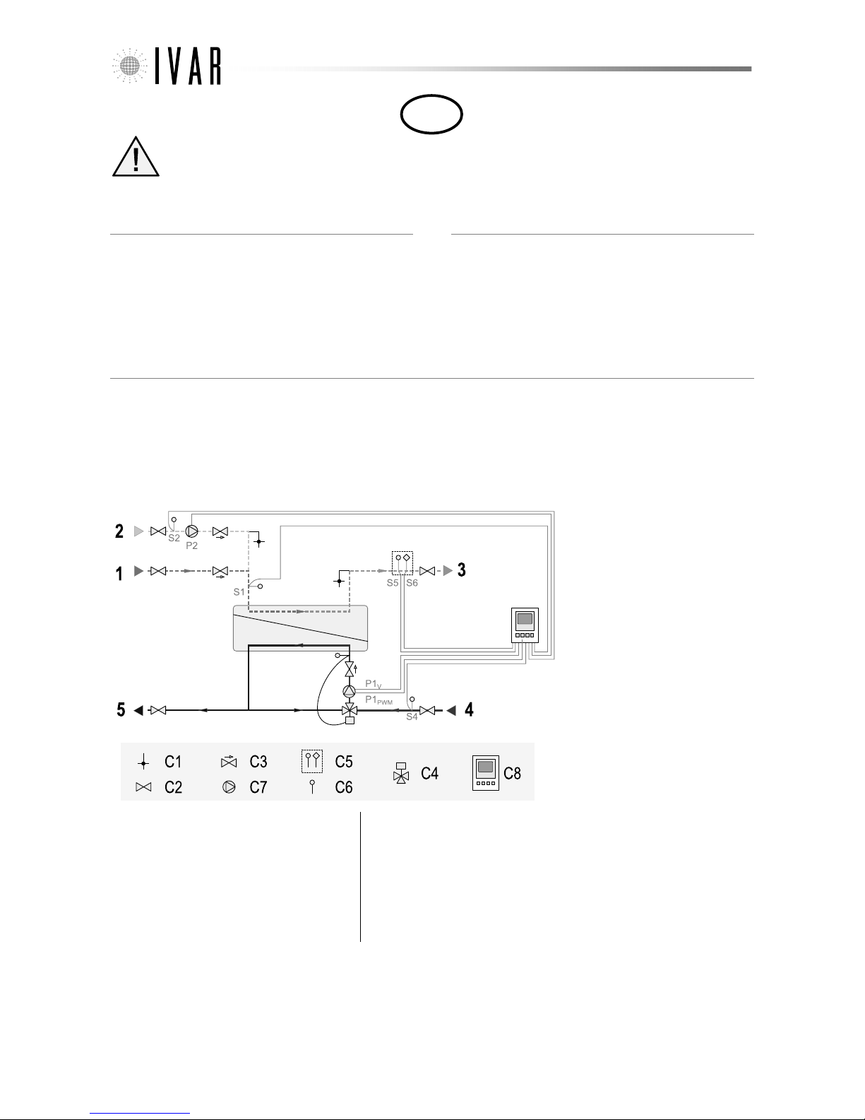
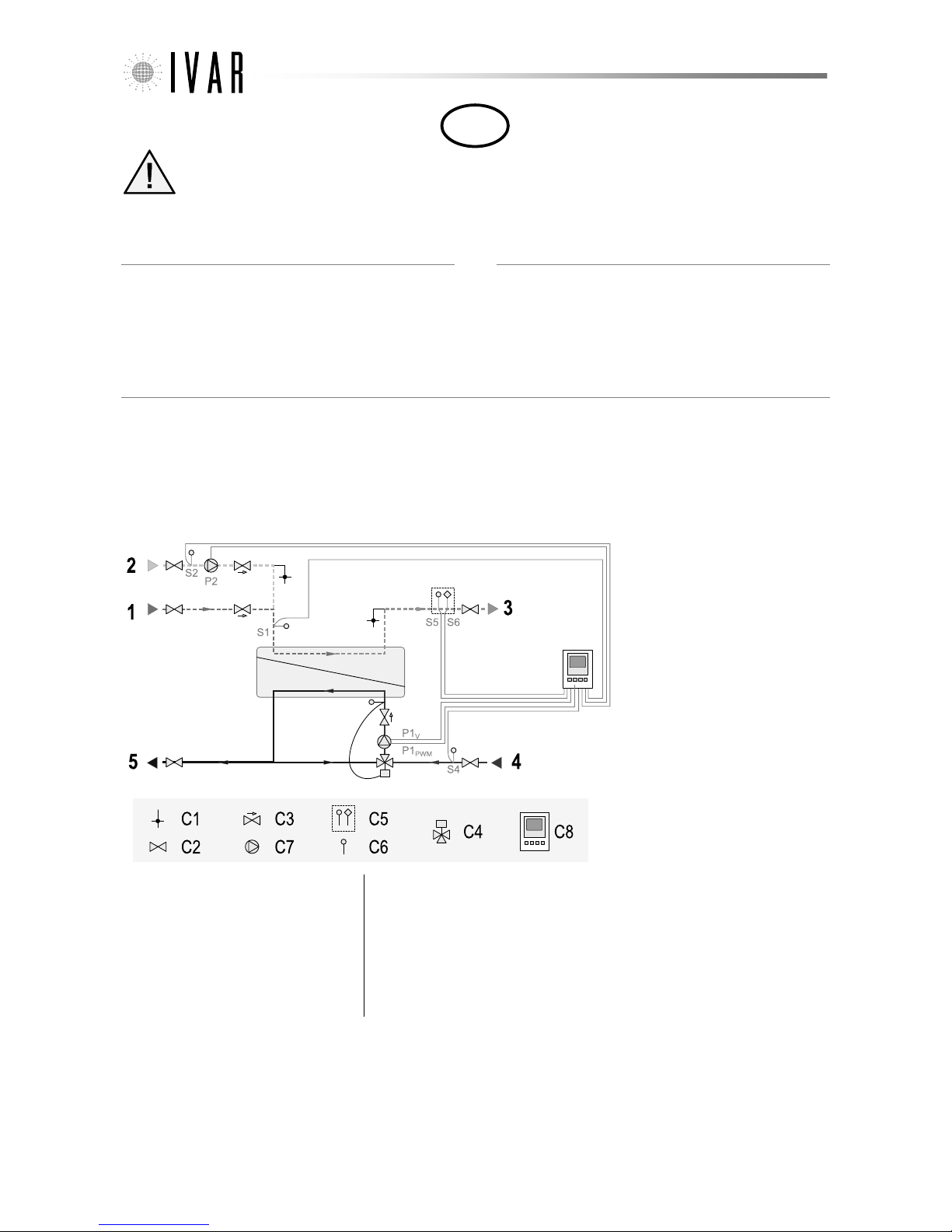
oder Unregelmäßigkeiten entfernen. Siehe Fig. 2a und Fig. 2b für die korrekte Ausführung der Anschlüsse. Die verwendeten Symbole haben folgende Bedeutung:
Vorlauf von
Speicherbehälter
(Primär)
Rücklauf zu
Speicherbehälter
(Primär)
Eintritt
Kaltwasser
(Trinkwasser)
Austritt
Warmwasser
(Trinkwasser)
Eintritt
Zirkulation
(Trinkwasser)
Die Verbindung zwischen SAP-Modul und primärseitigen Vor- und Rücklauf können mittels Quetschverschraubungen 1'' AG x DN und 1 1/4'' x DN (z. B. Verschraubungen IVAR
Art. RP 761 für Mehrschichtverbundrohr und RP 731 für PE-Rohr) ausgeführt werden, oder mit Pressfittings 1'' AG x DN und 1 1/4'' x DN (z. B. Fittings IVAR Art. MP 5608 für
Mehrschichtverbundrohr) für die Anschlüsse der Primär- und Sekundärkreise. Die Verbindung an die Zirkulationsleitung kann mittels Quetschverschraubungen 3/4'' AG x DN
(z. B. Verschraubungen IVAR Art. RP 761 für Mehrschichtverbundrohr und RP 731 für PE-Rohr) oder mit Pressfittings 3/4'' AG x DN (z. B. Fittings IVAR Art. MP 5608 für
Mehrschichtverbundrohr) ausgeführt werden. Es dürfen nur die spezifischen Fittings für den verwendeten Rohrtyp eingesetzt werden. Die Komponenten der Fittings in der
richtigen Reihenfolge montieren und das vom Hersteller angegebene Drehmoment für das verwendete Material und Rohrdurchmesser anwenden. Bei der Verwendung von
IVAR-Fittings wird daran erinnert, dass es verboten ist, die Gummiteile mit Ölen und Fetten auf Mineralölbasis zu schmieren, und empfohlen wird, nur Wasser zu verwenden.
Elektrischer Anschluss
⚠Achtung. Alle Arbeiten an elektrischen und elektronischen Komponenten der SAP-Module müssen von Fachpersonal entsprechend den geltenden gesetzlichen
Vorschriften durchgeführt werden.
Die SAP-Module werden vorverdrahtet geliefert. Die SAP-Module erfordern eine 230 VAC ±10 %, 50...60 Hz Versorgung, der Anschluss erfolgt über den vorgesehenen Schuko-
Stecker.

300459-10-2016
10/16
Inbetriebnahme
⚠Achtung. Vor Inbetriebnahme des Warmwasserbereiters sicherstellen, dass die Absperrkugelhähne vollständig geöffnet sind. Die Inbetriebnahme der Steuerung
muss durch Fachpersonal entsprechend der beiliegenden Steuerungsanleitung erfolgen, um Schäden an Anlagenteilen oder Gegenständen bzw. Verletzungen zu
vermeiden.
Das SAP-Modul nimmt sofort nach Herstellung der Stromversorgung den Betrieb auf. Die Steuerung muss bei der ersten Inbetriebnahme programmiert werden, hierzu
gehört die Eingabe des Temperatursollwerts für Warmwasser, die Schaltpunkte der Zirkulation, eventuelle besondere Betriebszyklen, usw.. Dieser Arbeitsschritt muss von
Fachpersonal entsprechend der beiliegenden Steuerungsanleitung durchgeführt werden. Insbesondere muss anhand des entsprechenden Thermometers geprüft werden,
dass die am Warmwasser-Temperaturregler eingestellte Temperatur der tatsächlichen Austrittstemperatur entspricht.
⚠Achtung.Es müssen die lokalen Vorschriften für die Einstellung der primärseitigen Eintrittstemperatur und der sekundärseitigen Austrittstemperatur beachtet
werden.
Die korrekten Parameter der Primärpumpe sind werkseitig eingestellt und sollten vom Anwender nicht geändert werden.
Wartung des Wärmetauschers
Es wird daran erinnert, dass hohe Temperaturen die Bildung von Kalkablagerungen auf der Sekundärseite (WW) des Wärmetauschers begünstigen, daher sollte die
Wasserhärte kontrolliert und die Eintrittstemperatur begrenzt werden. Bei besonders hartem Wasser und/oder zu hohen Temperaturen kann die Warmwasserseite des
Wärmetauschers verkalken. In diesem Fall kann die Sekundärseite des Wärmetauschers durch Anschluss eines externen Kreislaufs an die entsprechend Füll- (A) und
Entleerungshähne (B) gemäß Fig. 6 mit einer Reinigungsflüssigkeit gespült werden.
Die verwendete Reinigungsflüssigkeit hängt von der Art der Verschmutzung ab, für eine optimale Reinigung sollte die Durchflussmenge mindestens 1,5-mal höher als der
normale Betriebsdurchfluss sein. Nach der Reinigung muss der Wärmetauscher immer gründlich mit sauberem Wasser gespült werden, bevor der erneute Anschluss an das
Versorgungsnetz erfolgt. Sollte die Verwendung von sauren Lösungen erforderlich sein, muss sichergestellt werden, dass der pH-Wert nicht weniger als 2 beträgt und dass
alle Rückstände vor der letzten Spülung mit sauberem Wasser neutralisiert werden. Falls erforderlich pH-Messstreifen verwenden, um den pH-Wert am Austritt zu messen.
Leistungsdaten
Die Zahl im Produktcode jedes SAP-Moduls gibt die Nenngröße des Erzeugers in Litern pro Minute an, die mit primärseitiger Zulauftemperatur 60 °C und sekundärseitiger
Temperatur (Trinkwasser) 10 – 45 °C erreicht werden. Beispielsweise ist SAP-45E ein Modul, dass max. 45 l/min Wasser von 10 °C auf 45 °C bei einer stabilen primärseitigen
Zulauftemperatur von 60 °C erzeugt. Um die richtige Größe des SAP-Moduls zu wählen, sollte die Tabelle in Fig. 7 und Fig. 8 beachtet werden, die die Leistungswerte der
maximalen Warmwassermenge bei einer bestimmten Eintrittstemperatur T2in und einer bestimmten Austrittstemperatur T2out, mit einer primärseitigen
Vorlauftemperatur T1in darstellt. Die Einheitenlegende ist in Fig. 2b dargestellt.
⚠Achtung.Bei Modulen mit Mischventil ist die primärseitige Vorlauftemperatur des Wärmetauschers durch die Mischwirkung niedriger als die Temperatur des
Kessels oder des Speicherbehälters. Für die korrekte Verwendung der Tabellen der Fig. 8 muss die am Thermostatkopf (Mischwasser) eingestellte Temperatur für
„T1in“ gewählt werden.

300459-10-2016
11/16
Fig. 1
(a) (b)
Fig. 2

300459-10-2016
12/16
SAP-35(R)(E) SAP-45(R)(E) SAP-60(R)(E), SAP-80(R)(E), SAP-100(R)(E)
SAP-30M(R)(E) SAP-40M(R)(E) SAP-50M(R)(E), SAP-70M(R)(E), SAP-90M(R)(E)
Fig. 3
SAP-30(R)(E), SAP-30M(R)(E) SAP-45(R)(E), SAP-40M(R)(E) SAP-60(R)(E), SAP-80(R)(E), SAP-100(R)(E), SAP-
50M(R)(E), SAP-80M(R)(E), SAP-90M(R)(E)
Fig. 4

300459-10-2016
13/16
Yonos Para 25/7 PWM Stratos Para 25/1-8 Stratos Para 25/1-12
ZRS 12/2 ZRS 12/6
Fig. 5
Fig. 6

300459-10-2016
14/16
G2 [l/min] T1out [°C] G2 [l/min] T1out [°C] G2 [l/min] T1out [°C] G2 [l/min] T1out [°C] G2 [l/min] T1out [°C] G2 [l/min] T1out [°C] G2 [l/min] T1out [°C] G2 [l/min] T1out [°C] G2 [l/min] T1out [°C]
40 22.0 21.4 29.5 18.2 36.0 16.3 41.9 15.0 47.5 14.0 52.9 13.2 58.2 12.5 63.4 11.9 68.5 11.5
45 - - 21.2 24.0 28.2 20.4 34.0 18.2 39.4 16.7 44.4 15.5 49.2 14.5 54.0 13.8 58.6 13.1
50 - - - - 20.6 26.5 27.1 22.5 32.5 20.1 37.4 18.4 42.0 17.0 46.4 15.9 50.7 15.0
60--------19.831.625.626.930.323.934.521.838.520.1
40 23.6 23.3 32.0 20.6 39.1 18.9 45.8 17.8 52.1 17.0 58.3 16.3 64.3 15.8 70.2 15.3 76.1 15.0
45 - - 22.5 25.8 30.1 22.6 36.5 20.8 42.4 19.4 48.0 18.4 53.4 17.6 58.7 17.0 63.9 16.4
50 - - - - 21.7 28.3 28.7 24.7 34.6 22.6 39.9 21.1 44.9 19.9 49.8 19.0 54.4 18.2
60--------20.633.426.729.031.826.336.324.440.522.9
40 25.6 25.3 35.1 23.0 43.3 21.7 51.0 20.9 58.4 20.2 65.6 19.7 72.6 19.3 79.6 18.9 86.5 18.7
45 - - 24.1 27.8 32.5 25.1 39.7 23.5 46.3 22.4 52.7 21.5 58.8 20.9 64.8 20.4 70.7 19.9
50 - - - - 23.0 30.3 30.6 27.1 37.1 25.2 42.9 23.9 48.5 22.9 53.9 22.2 59.2 21.5
60--------21.635.228.131.233.528.838.327.142.925.8
G2 [l/min] T1out [°C] G2 [l/min] T1out [°C] G2 [l/min] T1out [°C] G2 [l/min] T1out [°C] G2 [l/min] T1out [°C] G2 [l/min] T1out [°C] G2 [l/min] T1out [°C] G2 [l/min] T1out [°C] G2 [l/min] T1out [°C]
40 28.6 19.5 37.8 16.4 45.6 14.5 52.7 13.1 59.4 12.1 65.9 11.4 72.2 10.7 78.4 10.2 84.6 9.8
45 - - 27.7 21.9 36.1 18.3 43.2 16.1 49.6 14.6 55.6 13.4 61.5 12.5 67.1 11.8 72.7 11.2
50 - - - - 26.9 24.2 34.8 20.2 41.3 17.8 47.2 16.0 52.7 14.7 58.0 13.7 63.1 12.8
60--------25.928.832.924.038.621.143.719.048.417.4
40 30.6 21.7 40.7 18.9 49.4 17.3 57.4 16.3 65.0 15.5 72.4 14.8 79.6 14.3 86.7 13.9 93.7 13.6
45 - - 29.3 24.0 38.5 20.8 46.2 18.9 53.3 17.6 60.0 16.7 66.5 15.9 72.8 15.3 79.0 14.8
50 - - - - 28.3 26.2 36.7 22.7 43.8 20.5 50.2 19.0 56.2 17.9 62.0 17.0 67.6 16.3
60--------26.930.834.326.440.423.845.821.950.920.4
40 33.1 24.0 44.5 21.7 54.4 20.4 63.6 19.6 72.5 19.0 81.1 18.5 89.6 18.1 97.9 17.8 106.2 17.5
45 - - 31.2 26.2 41.4 23.5 50.0 21.9 57.9 20.8 65.5 20.1 72.9 19.5 80.1 19.0 87.2 18.6
50 - - - - 29.9 28.4 39.1 25.3 46.8 23.4 53.8 22.2 60.5 21.2 67.0 20.5 73.3 19.9
60--------28.132.935.928.942.426.648.224.953.723.6
G2 [l/min] T1out [°C] G2 [l/min] T1out [°C] G2 [l/min] T1out [°C] G2 [l/min] T1out [°C] G2 [l/min] T1out [°C] G2 [l/min] T1out [°C] G2 [l/min] T1out [°C] G2 [l/min] T1out [°C] G2 [l/min] T1out [°C]
40 36.7 17.3 47.6 14.2 56.6 12.3 64.9 11.1 72.8 10.2 80.3 9.5 87.7 8.9 95.0 8.5 102.1 8.1
45 - - 35.6 19.4 45.5 15.8 53.8 13.7 61.3 12.2 68.3 11.2 75.1 10.3 81.7 9.7 88.1 9.2
50 - - - - 34.7 21.4 44.0 17.4 51.6 15.1 58.4 13.4 64.8 12.2 71.0 11.3 77.0 10.5
60--------33.425.541.720.748.317.854.215.859.714.3
40 39.0 19.8 51.0 17.1 61.1 15.6 70.4 14.6 79.2 13.8 87.8 13.3 96.3 12.8 104.6 12.5 112.8 12.2
45 - - 37.5 21.8 48.3 18.6 57.3 16.8 65.5 15.6 73.3 14.8 80.9 14.1 88.2 13.6 95.5 13.1
50 - - - - 36.3 23.8 46.2 20.2 54.4 18.2 61.9 16.8 68.9 15.7 75.6 14.9 82.2 14.3
60--------34.627.843.323.450.420.856.719.162.617.7
40 42.0 22.4 55.4 20.2 66.9 19.0 77.7 18.2 88.0 17.7 98.0 17.3 107.9 17.0 117.7 16.7 127.4 16.5
45 - - 39.8 24.3 51.6 21.7 61.7 20.2 70.9 19.2 79.8 18.5 88.3 18.0 96.7 17.6 105.0 17.3
50 - - - - 38.1 26.3 48.9 23.2 57.9 21.4 66.1 20.2 73.9 19.4 81.4 18.8 88.7 18.2
60--------36.030.245.226.352.724.059.522.465.921.3
G2 [l/min] T1out [°C] G2 [l/min] T1out [°C] G2 [l/min] T1out [°C] G2 [l/min] T1out [°C] G2 [l/min] T1out [°C] G2 [l/min] T1out [°C] G2 [l/min] T1out [°C] G2 [l/min] T1out [°C] G2 [l/min] T1out [°C]
40 52.2 19.5 68.9 16.3 83.0 14.5 95.9 13.2 108.1 12.2 119.9 11.4 131.5 10.8 142.8 10.2 153.9 9.8
45 - - 50.4 21.8 65.8 18.3 78.6 16.1 90.3 14.6 101.3 13.4 111.9 12.5 122.2 11.8 132.3 11.2
50 - - - - 49.1 24.2 63.4 20.2 75.3 17.7 85.9 16.0 96.0 14.7 105.6 13.7 114.9 12.9
60--------47.228.859.924.070.321.179.519.088.217.4
40 55.7 21.7 74.2 18.9 89.9 17.3 104.4 16.3 118.3 15.5 131.7 14.9 144.9 14.4 157.8 13.9 170.6 13.6
45 - - 53.4 23.9 70.1 20.8 84.1 18.9 97.0 17.6 109.2 16.7 121.0 15.9 132.5 15.3 143.8 14.8
50 - - - - 51.6 26.2 66.9 22.6 79.7 20.5 91.3 19.0 102.3 17.9 112.9 17.0 123.1 16.3
60--------49.130.862.526.473.523.883.421.992.620.5
40 60.3 24.0 81.1 21.7 99.1 20.4 115.8 19.6 131.9 19.0 147.6 18.5 163.0 18.1 178.3 17.8 193.4 17.6
45 - - 56.9 26.2 75.3 23.5 91.0 21.9 105.5 20.9 119.3 20.1 132.7 19.5 145.8 19.0 158.7 18.6
50 - - - - 54.4 28.4 71.1 25.3 85.2 23.4 98.0 22.2 110.1 21.2 121.9 20.5 133.3 19.9
60--------51.132.965.428.977.226.687.824.997.823.7
G2 [l/min] T1out [°C] G2 [l/min] T1out [°C] G2 [l/min] T1out [°C] G2 [l/min] T1out [°C] G2 [l/min] T1out [°C] G2 [l/min] T1out [°C] G2 [l/min] T1out [°C] G2 [l/min] T1out [°C] G2 [l/min] T1out [°C]
40 65.4 21.1 87.6 18.0 106.4 16.1 123.7 14.8 140.1 13.8 156.0 13.0 171.4 12.4 186.7 11.8 201.7 11.3
45 - - 63.2 23.6 83.6 20.1 100.7 18.0 116.3 16.4 131.1 15.3 145.3 14.4 159.1 13.6 172.7 12.9
50 - - - - 61.4 26.1 80.4 22.2 96.2 19.8 110.5 18.1 124.0 16.8 136.9 15.7 149.4 14.9
60--------59.031.275.926.589.723.6102.1 21.5 113.6 19.8
40 70.2 23.0 94.7 20.4 115.7 18.8 135.2 17.7 153.8 16.9 171.8 16.2 189.5 15.7 206.8 15.3 224.1 14.9
45 - - 67.0 25.5 89.3 22.4 108.0 20.5 125.3 19.2 141.7 18.3 157.5 17.5 173.0 16.9 188.1 16.3
50 - - - - 64.7 28.0 85.1 24.5 102.2 22.3 117.8 20.8 132.5 19.7 146.7 18.8 160.5 18.0
60--------61.433.079.328.694.026.0107.2 24.1 119.6 22.6
40 76.2 25.1 103.9 22.9 128.0 21.6 150.5 20.7 172.1 20.1 193.2 19.6 213.9 19.2 234.4 18.9 254.7 18.6
45 - - 71.7 27.5 96.3 24.9 117.3 23.3 136.7 22.2 155.2 21.4 173.2 20.8 190.9 20.3 208.2 19.9
50 - - - - 68.5 30.0 90.7 26.9 109.5 25.0 126.7 23.7 143.1 22.8 158.9 22.0 174.3 21.4
60--------64.234.983.230.999.028.6113.2 26.9 126.6 25.6
5
10
5
10
15
5
55 60 65
T1in [°C]
T1in [°C]
T1in [°C]
T1in [°C]
5045
8545 50
45 50
8545 50 75 80
SAP-60E/SAP-60RE
T2in [°C]
T2out
[°C]
55 60
10
15
SAP-80E/SAP-80RE
T2in [°C]
T2out
[°C]
55 60 65 70 75
5
10
15
SAP-100E/SAP-100RE
T2in [°C]
T2out
[°C]
70
5
10
15
45 50
SAP-45E/SAP-45RE
T2in [°C]
T2out
[°C]
55 60 65 70 75
65 70 75 80
85
15
80
80
85
SAP-35E/SAP-35RE
T2in [°C]
T2out
[°C]
55 60 65 70 75 80 85
T1in [°C]
Fig. 7

300459-10-2016
15/16
G2 [l/min] T1out [°C] G2 [l/min] T1out [°C] G2 [l/min] T1out [°C] G2 [l/min] T1out [°C] G2 [l/min] T1out [°C]
40 20.7 20.9 27.7 17.8 33.6 15.9 39.1 14.5 44.3 13.5
45 - - 20.0 23.5 26.4 19.9 31.8 17.7 36.8 16.2
50 - - - - 19.4 26.0 25.5 22.0 30.4 19.5
60--------18.730.9
40 22.2 22.9 30.0 20.2 36.6 18.5 42.7 17.4 48.6 16.6
45 - - 21.2 25.4 28.2 22.2 34.2 20.3 39.6 19.0
50 - - - - 20.5 27.8 26.9 24.2 32.3 22.1
60--------19.432.8
40 24.1 25.0 32.9 22.7 40.5 21.4 47.6 20.5 54.4 19.9
45 - - 22.7 27.4 30.5 24.7 37.1 23.1 43.2 22.0
50 - - - - 21.7 29.8 28.7 26.6 34.6 24.8
60--------20.334.7
G2 [l/min] T1out [°C] G2 [l/min] T1out [°C] G2 [l/min] T1out [°C] G2 [l/min] T1out [°C] G2 [l/min] T1out [°C]
40 26.2 19.0 34.4 15.8 41.3 13.9 47.7 12.6 53.7 11.6
45 - - 25.3 21.2 32.9 17.6 39.2 15.4 44.9 13.9
50 - - - - 24.7 23.5 31.7 19.4 37.5 17.0
60--------23.728.0
40 27.9 21.2 37.0 18.4 44.7 16.8 51.9 15.8 58.7 15.0
45 - - 26.8 23.4 35.0 20.2 41.9 18.3 48.2 17.1
50 - - - - 25.9 25.6 33.4 22.0 39.7 19.9
60--------24.630.0
40 30.2 23.6 40.4 21.3 49.2 20.0 57.5 19.2 65.3 18.6
45 - - 28.5 25.7 37.6 23.0 45.3 21.4 52.4 20.4
50 - - - - 27.3 27.9 35.5 24.7 42.4 22.9
60--------25.732.2
G2 [l/min] T1out [°C] G2 [l/min] T1out [°C] G2 [l/min] T1out [°C] G2 [l/min] T1out [°C] G2 [l/min] T1out [°C]
40 33.2 16.7 42.7 13.6 50.7 11.8 58.0 10.6 64.9 9.7
45 - - 32.1 18.7 40.9 15.2 48.2 13.1 54.8 11.7
50 - - - - 31.3 20.7 39.5 16.7 46.2 14.4
60--------30.224.6
40 35.2 19.3 45.7 16.6 54.6 15.1 62.8 14.1 70.6 13.4
45 - - 33.8 21.2 43.3 18.1 51.3 16.3 58.5 15.1
50 - - - - 32.8 23.1 41.5 19.6 48.7 17.6
60--------31.327.0
40 37.8 22.0 49.6 19.8 59.8 18.7 69.2 17.9 78.3 17.4
45 - - 35.8 23.8 46.3 21.2 55.1 19.8 63.3 18.8
50 - - - - 34.4 25.7 43.9 22.6 51.8 20.9
60--------32.529.5
G2 [l/min] T1out [°C] G2 [l/min] T1out [°C] G2 [l/min] T1out [°C] G2 [l/min] T1out [°C] G2 [l/min] T1out [°C]
40 45.8 18.7 60.0 15.5 71.9 13.6 82.8 12.3 93.2 11.4
45 - - 44.3 20.9 57.4 17.3 68.2 15.1 78.1 13.6
50 - - - - 43.1 23.1 55.3 19.1 65.3 16.7
60--------41.527.5
40 48.8 20.9 64.5 18.2 77.8 16.6 90.1 15.6 101.8 14.8
45 - - 46.8 23.1 61.0 19.9 72.8 18.1 83.7 16.8
50 - - - - 45.2 25.3 58.3 21.7 69.1 19.6
60--------43.129.6
40 52.7 23.4 70.3 21.1 85.5 19.9 99.7 19.0 113.3 18.4
45 - - 49.8 25.5 65.4 22.8 78.7 21.2 90.9 20.2
50 - - - - 47.7 27.6 61.8 24.4 73.7 22.6
60--------44.831.9
G2 [l/min] T1out [°C] G2 [l/min] T1out [°C] G2 [l/min] T1out [°C] G2 [l/min] T1out [°C] G2 [l/min] T1out [°C]
40 56.9 20.1 75.5 16.9 91.2 15.1 105.7 13.7 119.3 12.8
45 - - 55.0 22.5 72.1 18.9 86.4 16.8 99.4 15.3
50 - - - - 53.5 24.9 69.5 20.9 82.7 18.5
60--------51.429.7
40 60.9 22.2 81.4 19.5 99.0 17.9 115.2 16.8 130.7 16.0
45 - - 58.2 24.5 76.9 21.4 92.6 19.5 106.9 18.2
50 - - - - 56.2 26.9 73.4 23.3 87.7 21.2
60--------53.531.6
40 65.9 24.4 89.1 22.1 109.2 20.9 128.0 20.0 146.0 19.4
45 - - 62.2 26.7 82.7 24.0 100.2 22.4 116.4 21.3
50 - - - - 59.4 29.0 78.1 25.9 93.7 24.0
60--------55.833.6
5
SAP-30ME/SAP-30MRE
T1in [°C]
SAP-40ME/SAP-40MRE
T1in [°C]
5
10
15
T2in [°C]
T2out
[°C]
55 60
T2in [°C]
T2out
[°C]
55 60 6545 50
T1in [°C]
5
10
15
SAP-50ME/SAP-50MRE
50
T2in [°C]
T2out
[°C]
55 60 65
T1in [°C]
SAP-90ME/SAP-90MRE
T2in [°C]
T2out
[°C]
55 60 6545 50
45 50
5
10
15
T1in [°C]
SAP-70ME/SAP-70MRE
45 50
10
15
T2in [°C]
T2out
[°C]
55 60 6545
5
65
10
15
Fig. 8

300459-10-2016
16/16
Notes
....................................................................................................................................................................................................................................................................................................................
....................................................................................................................................................................................................................................................................................................................
....................................................................................................................................................................................................................................................................................................................
....................................................................................................................................................................................................................................................................................................................
....................................................................................................................................................................................................................................................................................................................
....................................................................................................................................................................................................................................................................................................................
....................................................................................................................................................................................................................................................................................................................
....................................................................................................................................................................................................................................................................................................................
....................................................................................................................................................................................................................................................................................................................
....................................................................................................................................................................................................................................................................................................................
....................................................................................................................................................................................................................................................................................................................
....................................................................................................................................................................................................................................................................................................................
....................................................................................................................................................................................................................................................................................................................
....................................................................................................................................................................................................................................................................................................................
....................................................................................................................................................................................................................................................................................................................
....................................................................................................................................................................................................................................................................................................................
....................................................................................................................................................................................................................................................................................................................
....................................................................................................................................................................................................................................................................................................................
....................................................................................................................................................................................................................................................................................................................
....................................................................................................................................................................................................................................................................................................................
....................................................................................................................................................................................................................................................................................................................
....................................................................................................................................................................................................................................................................................................................
....................................................................................................................................................................................................................................................................................................................
....................................................................................................................................................................................................................................................................................................................
....................................................................................................................................................................................................................................................................................................................
....................................................................................................................................................................................................................................................................................................................
....................................................................................................................................................................................................................................................................................................................
....................................................................................................................................................................................................................................................................................................................
....................................................................................................................................................................................................................................................................................................................
....................................................................................................................................................................................................................................................................................................................
....................................................................................................................................................................................................................................................................................................................
....................................................................................................................................................................................................................................................................................................................
....................................................................................................................................................................................................................................................................................................................
....................................................................................................................................................................................................................................................................................................................
....................................................................................................................................................................................................................................................................................................................
....................................................................................................................................................................................................................................................................................................................
....................................................................................................................................................................................................................................................................................................................
....................................................................................................................................................................................................................................................................................................................
This manual suits for next models
26
Table of contents
Languages:
Popular Water System manuals by other brands

Everpure
Everpure Claris EV4339-10 Specification sheet

SpectraPure
SpectraPure RO Systems instructions

Stulz
Stulz CyberWall CAH Installation, operation and maintenance manual

Energy Plus
Energy Plus VTS30HP Manual of installation and use

Spirotech
Spirotech SPIROVENT SUPERIOR S250 user manual

AVK
AVK A2780 FIELD MAINTENANCE AND INSTRUCTION MANUAL

dosatron
dosatron D 25 F owner's manual

Infiltrator
Infiltrator delta ENVIRO-AIRE EA50 Installation, operation and maintenance manual

Zip
Zip 5253UK installation instructions

Armstrong
Armstrong AG Series Installation and operating instructions

PowerOptimal
PowerOptimal Elon 100 Installation and user manual

Argo-Hytos
Argo-Hytos OPS 010 manual