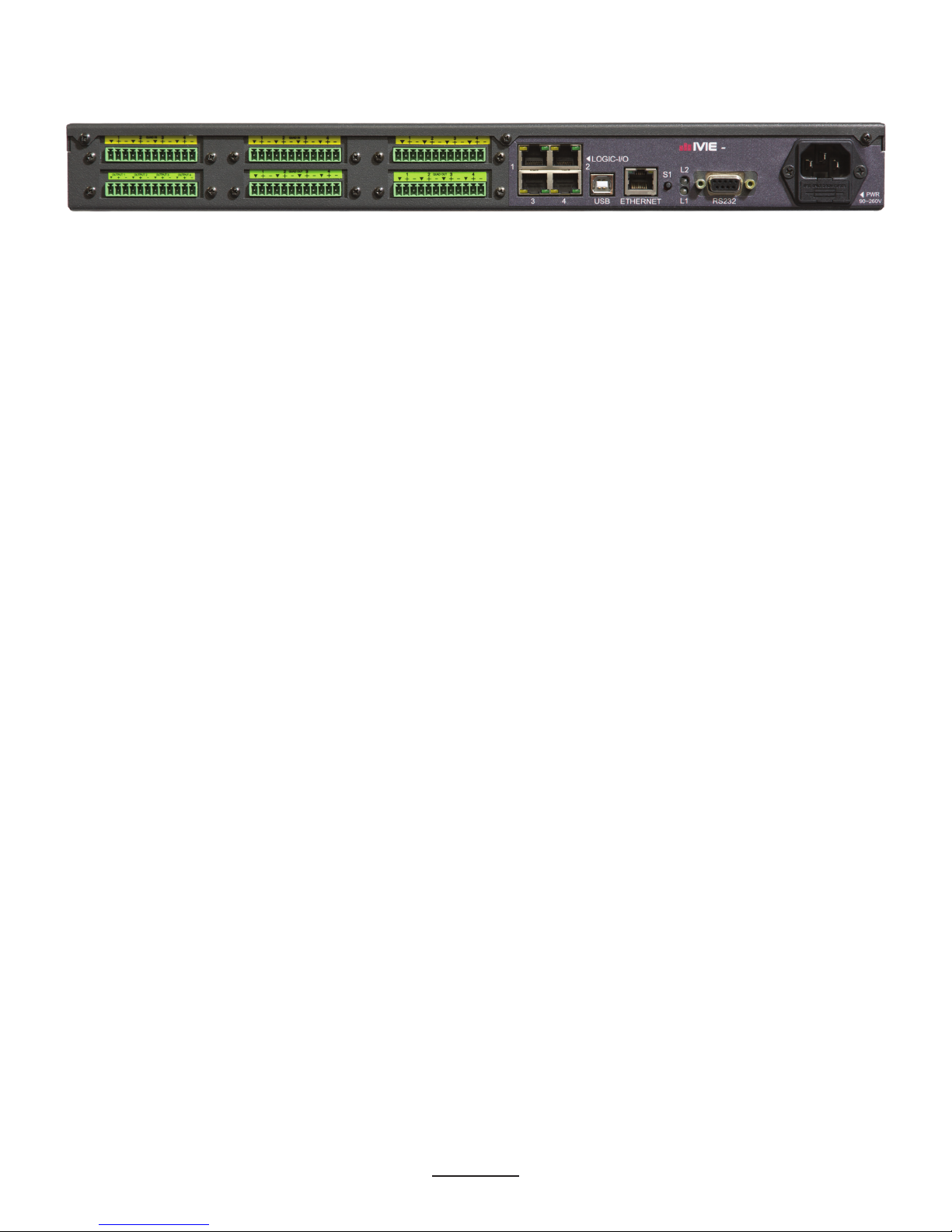
IVIE iFlex 620 User manual

MAP Series Audio Mixer
Installation Guide
Model: iFlex 620
Firmware Rev: 2.065
IP Address: 192.168.0.150
Subnet Mask: 256.256.256.0
Serial Number: 2051A306D2
Date: 5/12/2014
Time: 11:27:14

1
Front Panel Display
MAP series audio mixers incorporate a high resolution touch-screen display to provide information on system
connection, setup, diagnostics, channel state, etc. To navigate through the display screens, swipe either left or
right using the touch-screen**. The Ivie splash screen is the default screen on system boot-up. This is a low
intensity display for low-light environments.
SWIPE M1
123
+20
0
-20
-40
+20
0
-20
-40
M2
1 2 3 4
M3
1 2 3 4
C
4
Model: iFlex 620
Firmware Rev: 2.065
IP Address: 192.168.0.150
Subnet Mask: 256.256.256.0
Serial Number: 2051A306D2
Date: 5/12/2014
Time: 11:27:14
Sytem Information Screen
The system information screen is a single, right-to-left swipe of the touchscreen from the default boot-up splash
screen. This screen shows information on the mixer model number, rmware revision, current IP address and
subnet mask, serial number, date, and time.
Model: iFlex 620
Firmware Rev: 2.065
IP Address: 192.168.0.150
Subnet Mask: 256.256.256.0
Serial Number: 2051A306D2
Date: 5/12/2014
Time: 11:27:14
Channel Display
The channel display shows information on currently loaded hardware modules, channel levels, and clipping
status. The levels are calibrated levels, and dynamically update to provide real-time level response for all audio
input and output channels. Only audio channels are displayed. Channels are color coded to indicate type (input,
output, echo-canceling, digital, FIR, etc.). Clipping is indicated by a hatched level, and a ‘C’ notation above the
channel bar.
M1
12
+20
0
-20
-40
+20
0
-20
-40
M2 M3
1234
C
43 12 43 12 43 1234 1234
M4 M5 M6
** Note - The touchscreen is resistive, and works best if the ‘swipe’ is done with a point-source, such as a n-
gernail, as opposed to the at of the nger.

2
Rear Panel
- MAP 6L
AC Mains
The AC Mains input is a switching power supply that will accept 100V to 240V, and 50/60Hz. Receptacle is
fused with a 5X20MM, 1A 250VAC Slo-Blo fuse. Spare fuse included.
RS232
The serial port allows 3rd-party controllers to congure/control/monitor the MAP unit. This port also is also
capable of sending data (in Decimal, Hexidecimal, ASCII, Binary, BYTES, etc.) to control 3rd-party devices.
This provides control to nearly any 3rd-party device with a dened protocol.
L1/L2
L1 and L2 are LED indicators for system status. L1 indicates power, and L2 indicates processor main thread
activity.
S1
The ‘S1’ switch is used at power-up to place the unit in ‘safe-boot’ mode. On boot up, when the ‘L2’ indicator
is still blinking, briey press the ‘S1’ button. The ‘L2’ indicator will stop blinking, indicating that the device is
in ‘safe boot’ mode. If ‘L2’ continues to blink, then the button was pushed too late in the power-up process.
Ethernet
This connection is for TCPIP communications for programming, control, and network audio. This port can be
used to send le layouts to and from the MAP unit, as well as monitor/control a unit layout in real-time using
the SonataTM software. This port is also used for sending ethernet commands (UDP or TCP, in Decimal, Hexa-
decimal, ASCII, Binary, BYTES, etc.), to control 3rd-party devices. This makes it possible to control nearly
any 3rd-party device with a dened protocol.
Ethernet Audio Channels
iFlex units are able to send ethernet audio channels to other iFlex units over standard ethernet connections,
switches, and routers. The MAP series is part of the iFlex family of products, and can share conguration,
control, and ethernet audio channels with any other iFlex family product(s). This sharing can be through either
UDP broadcast channels, or point-to-point TCP channels.
Note - A DANTE ethernet audio option will soon be available as an I/O module.
The MAP series has added a system clock coordination feature that will syncronize all MAP units in a system
layout to the same frequency. This syncronization is performed automatically when any MAP units sees data
from another MAP unit. This provides the highest quality audio between MAP sytem units.
IGMP Switching/Routing
When iFlex ethernet audio is switched/routed using IGMP capable switches and routers, and used in combina-
tion with the clock-sycronizing feature of the MAP units, high quality ethernet audio channels are routed only

3
between source and destination channels. Ethernet audio channels only go to those destination channels that
request them, and the coordination of these sources and destinations is handled by the IGMP switch/router.
USB
Like the ethernet connection, the USB connection can be used to program, monitor, and control the MAP-6L
(no USB connection available on a MAP-3 unit). This connection can be used to send and receive les from the
MAP unit, as well as congure the unit, and control any system layout. Unlike the ethernet connection, there
are no audio channels available via USB.
Logic I/O
The Logic I/O ports on the rear panel of a MAP unit are RS-485 communication ports for Ivie SmartControls©,
as well as physical controls, such as potentiometers, contact closures, and LED outputs. Any Ivie SmartCon-
trol©that is plugged into this port will self-identify in the hardware programming screen for assignment to
layout elements. Ivie SmartControls©use standard CAT-5E or better cables.
Note - Ivie SmartControls©require +24VDC power, which is supplied on pins 4 and 5 of the
RJ45 connector. For consistency in iFlex installations, and assistance in technical support, Ivie
uses the TIA/EIA 568B standard for RJ45 connector wiring. Care should be taken in the wiring
of RJ45 connectors on the CAT-5e cable, as cross-wiring of the +24VDC can cause damage to
the RS485 communications electronics inside the MAP unit.
12345678
RJ45 JACK
TIA/EIA 568B STANDARD
The pinout for the Logic I/O ports is shown below.
Pin Assignment
1 Switch in (RS-485 Data A)
2 Pot wiper (RS-485 Data B)
3 Remote + (10 VDC)
4 +24 VDC
5 +24 VDC
6 LED out (RS-485 Reset)
7 Ground
8 Ground

4
Control Inputs
Each control port can support either RS485 smart controls, or 1 analog switch, 1 analog potentiometer, and 1
logic output. The number of analog controls, and logic outputs can be dramatically increased by the use of an
RMPC I/O expander. RMPC expanders allow a 4, 8, or 12 fold expansion of the number of analog controls,
and logic outputs, and combine them into a smart control with a single CAT5E or better cable back to the MAP
device control port.
Switches
Switches inputs are internally ‘pulled up’ to +5VDC via 1kOhm resistor. No external voltage source is neces-
sary to create contact closure to ground. Switches are wired from pin 1 to pin 7 or pin 8 of the RJ45 connector.
12345678
RJ45 JACK
TIA/EIA 568B STANDARD
Switch
Potentiometers
Potentiometers are wired with reference +10V on pin 3, a wiper on pin 2, and a ground on pin 7, or pin 8. High
performance pots with track resistance between 10kOhms and 100kOhms are recommended.
12345678
RJ45 JACK
TIA/EIA 568B STANDARD
Reference = 10V
Wiper
Ground

5
Selectors
Analog selector controls are wired with pin 3 being the reference voltage (+10V), pin 2 being the wiper, and
pin 7 or 8 being the ground. A resistance ladder is added with the value of the resistors being recommended at
2.2kOhms.
12345678
RJ45 JACK
TIA/EIA 568B STANDARD
Reference = 10V
Wiper
Ground
2.2kR
Logic Onputs
Each logic output can control an LED or low power relay. Pin 6 of the RJ45 jack has a 50k Ohm ‘pull-up’ to
12V DC when not asserted. When asserted, it will sink 25mA at 0.6V DC. Maximum asserted external voltage
is 30V DC. For logic outputs that will drive LED’s directly (without any other source), see the RMPC line of
I/O expander modules. See also the ‘Relay’ module of the MAP series module list for power relay options.
I/O Modules
All MAP modules are color coded for ease of identication. Modules are labeled with these colors in 2 places
- the back panel, and the front panel display. On the back panel the modules have color-coded labels. On the
front panel display, audio channel numbers are displayed in the different colors. The list of modules and their
colors is listed below.
Module Color
Quad-In Yellow
Quad-Out Green
Dual-I/O Yellow&Green
Quad-AEC Orange
Quad-FIR Blue
Quad-AES-In Black
Quad-AES-Out White
Quad-Tel Red
Relay Gray
Tri-Control Purple

6
Audio cable connections are made via euro-block (or Phoenix) pluggable connectors (supplied with the MAP
unit). Inputs can be either 2 or 3 wire connections as shown below. Unbalanced inputs (2 wire) should have a
jumper installed between the sheild pin and the negative pin of the connector to reduce noise. Balanced outputs
(3 wire) should not connect the shield at the receiving device. To prevent ground loop issues between devices,
the shield pin is only connected at the sending device.
M1
M4
1 2 3 4
QUAD IN
3 Wire 2 Wire
1 2 3 4
QUAD OUT
3 Wire 2 Wire
INPUTS
SHIELD
OUTPUTS
SHIELD
Technical Specications:
Frequency response(20 Hz - 20 KHz)
THD+N (20 Hz - 20KHz )
Equivalent Input Noise (20 Hz - 20 KHz)
Dynamic Range (20Hz - 20KHz, 0dB)
Crosstalk (channel to channel @ 1 KHz)
Line level
Mic level
Input Impedance
Line (balanced)
Mic (balanced)
Maximum Input
Input Gain Range (6 dB steps)
Output Impedance (balanced)
Maximum Output (balanced)
Sampling Rate
A/D - D/A Convertors (bit rate)
Phantom Power
Control Network(s):
Connectors:
+0/- 0.25dB
.01%@10dBV Output
< -125dBu
> 108dB
< -75dB
< -75dB
30 KOhms
2 KOhms
+24dBu
0 - 60 dB
200 Ohms
+24dBu
48 KHz
24-bit
48V open circuit
14mA short circuit
Ethernet, USB
RJ45
Table of contents
Other IVIE Music Mixer manuals