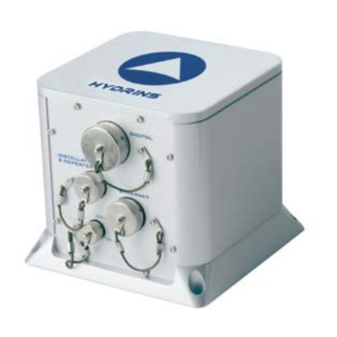
iXBlue ROVINS Parts list manual

Rovins
Technical Description


Rovins -Technical Description
Revision History
Edition Date Comments
A07/2019 Creation
B 03/2020 Navigation data & settling time chapters updated
MU-ROVINSTD-AN-001-B - March 2020 3

Rovins -Technical Description
Copyright
All rights reserved. No part of this manual may be reproduced or transmitted, in any form or by
any means, whether electronic, printed manual or otherwise, including but not limited to
photocopying, recording or information storage and retrieval systems, for any purpose without
prior written permission of iXblue.
Disclaimer
iXblue specifically disclaims all warranties, either expressed or implied, including but not limited
to implied warranties about merchantability and fitness for a particular purpose with respect to
this product and documentation. iXblue reserves the right to revise or to make changes or
improvements to this product or documentation at any time without notify any person of such
revision or improvements.
In no event shall iXblue be liable for any consequential or incidental damages, including but not
limited to loss of business profits or any commercial damages, arising out of the use of this
product.
Trademarks
Microsoft, MS-DOS and Windows are registered trademarks of Microsoft Corporation.
Intel and Pentium are registered trademarks and Celeron is a trademark of Intel Corporation.
Export Control
This product is subject to export control regulations. Please refer to the commercial offer or
contact iXblue for details about the applicable export control regulations and restrictions.
4MU-ROVINSTD-AN-001-B - March 2020

Rovins -Technical Description
Rovins Documentation
The following documents give all the information you need in order to understand and to use
your product.
●Rovins Technical Description (ref.: MU-ROVINSTD-AN-001)
>Rovins and iXblue technology presentation
>Technical specifications
>Certification and qualification, life cycle
>Mechanical, electrical and communication interface description
●Rovins Installation & Setup Guide (ref.: MU-ROVINSISG-AN-001)
>Conventions
>Physical and electrical installation
>Connecting to the Web-Based Graphical User Interface
>Setup the Rovins
>Contacting iXblue support
●Rovins Operation Guide (ref.: MU-ROVINSOG-AN-001)
>Introduction to the Inertial Navigation System
>Start-up Phases
>Web-Based Graphical User Interface description
>Configuring the navigation parameters & managing the external information
>Viewing the system information
>Recording data
●Rovins Interface Library (ref.: MU-ROVINSIL-AN-001)
>NMEA frames
>Digital input and output protocols
>Pulses interfaces specification
>Control commands
●Rovins Quick Start Guide
>Pack content verifying
>Installing and connecting Rovins
>Configuring and operating Rovins
●SEACON 12 PIN TI 1M Pigtail Cable - Product Description (Ref.: MU-PDCABLES-
AN-001)
>cable and pinout of the SEACON 12 pins Pigtail Cable
●SEACON 19 PIN TI 1M Pigtail Cable - Product Description (Ref.: MU-PDCABLES-
AN-002)
>cable and pinout of the SEACON 19 pins Pigtail Cable
●SEACON 26 PIN TI 1M Pigtail Cable - Product Description (Ref.: MU-PDCABLES-
AN-003)
>cable and pinout of the SEACON 26 pins Pigtail Cable
●Subsea Inertial Products - Illustrated Part Catalog (ref.: MU-SUBSEADP-AN-001)
>Detailed part list
>Alphanumerical Index
●Application Note - INS+DVL Calibration (ref.: MU-DVLINS-AN-001)
>Configuring the calibration
>Calibrating the DVL+INS
MU-ROVINSTD-AN-001-B - March 2020 5

Rovins -Technical Description
●Application Note - Installation and Configuration of AHRS and INS for Seabed
Mapping Measurements (ref.: MU-HEAVAPN-AN-001)
>Using heave compensation on seabed mapping
>Effect of vessel transient movements
6MU-ROVINSTD-AN-001-B - March 2020

Rovins -Technical Description
Rovins Technical Description Overview
This document must be read and understood prior to using the product.
The manufacturer shall in no case be held liable for any application or use that does not comply
with the stipulations in this manual.
The Rovins Technical Description is divided into several parts:
●Part 1: Rovins Description
This part contains the description of the main product parts and the presentation of iXblue
technology.
●Part 2: Technical Specification
This part gives details on the technical specifications, the certification, qualifications and
the life cycle.
●Part 3: Mechanical Description
This part describes mechanical aspect of Rovins, except connectors.
●Part 4: Electrical interface Description
This part gives the detail of the electrical interface (connector, pinout description and
electrical levels).
●Part 5: Communication Interface Description
This part details the interfaces to communicate with Rovins.
MU-ROVINSTD-AN-001-B - March 2020 7

Rovins -Technical Description
Abbreviations and Acronyms
ACC Accelerometer
EGNOS European Geo-stationary Navigation Overlay Service
Galileo European Satellite Navigation System
GLONASS Global Navigation Satellite System (operated by the Russian
Space Forces)
GNSS Global Navigation Satellite System
GPS Global Positioning System (operated by the United States Depart-
ment of Defense)
GST GPS Pseudo-range Noise (PRN) statistics (The GST message is
used to support Receiver Autonomous Integrity Monitoring)
GUI Graphical User Interface
HRP Heading, Roll, Pitch
IMU Inertial Measurement Unit
INS Inertial Navigation System
IP Internet Protocol
LVA Lever Arms
MU Measurement Unit
PPS Pulse Per Second
RTK Real Time Kinematic
SD Standard Deviation
Seclat Secant latitude = 1 / cosine latitude
ROV Remotely Operated Vehicle
UTC International acronym for Coordinated Universal Time (CUT)
UTM Universal Transverse Mercator
VTG Vector Track and speed over Ground
WEEE Waste Electrical and Electronic Equipment
WGS-84 World Geodetic System 1984
ZDA Time and Date (The ZDA message identifies UTC time, day,
month, and year, local zone number, and local zone minutes)
ZUPT Zero velocity UPdaTe
8MU-ROVINSTD-AN-001-B - March 2020

Rovins -Technical Description
Table of Contents
1 ROVINS DESCRIPTION 11
1.1 IXBLUE TECHNOLOGY 11
1.2 ROVINS DATA AVAILABILITY 13
1.3 EXTERNAL SENSORS 14
2 TECHNICAL SPECIFICATION 15
2.1 PERFORMANCE PREREQUISITES 15
2.2 EQUIPMENT DATA DYNAMIC RANGE 16
2.3 EXTERNAL SENSORS 16
2.4 NAVIGATION DATA 17
2.5 INPUT / OUTPUT 18
2.6 POWER SUPPLY 18
2.7 EXPORT LIMITATIONS 19
2.8 SETTLING TIME 20
2.9 QUALIFICATIONS 22
2.10 LIFE CYCLE 23
2.10.1 Packaging, Handling, Storage, Transportation requirements 23
2.10.2 Auto-calibration 23
2.10.3 Built-in-test 23
2.10.4 Reliability & maintainability 23
3 MECHANICAL DESCRIPTION 24
3.1 PRESENTATION AND OVERALL DIMENSIONS 24
3.2 MECHANICAL ALIGNMENT 24
3.3 REFERENCE FRAME CENTER 24
4 ELECTRICAL INTERFACE DESCRIPTION 26
4.1 OVERVIEW OF ELECTRICAL INTERFACE 26
4.2 LISTING OF INTERFACES 27
4.3 ETHERNET CONNECTOR SPECIFICATION 28
4.3.1 Definition 28
4.3.2 Connector & Pin out 29
4.4 PORT A&B CONNECTOR (CENTRAL CONNECTOR) SPECIFICATIONS 30
4.4.1 Definition 30
4.4.2 Connector and Pinout 31
4.5 PORT X (X BEING C, D, OR E) CONNECTOR SPECIFICATIONS 32
4.5.1 Definition 32
4.5.2 Connector and Pinout 33
4.6 ROVINS POWER NETWORK 34
4.6.1 Power Supply Definition 34
4.6.2 Power Supply Pinout 34
4.7 RECOMMENDED WIRING 35
4.8 RS232/RS422 INPUT AND OUTPUT CHARACTERISTICS 39
4.9 INPUT PULSES ELECTRICAL CHARACTERISTICS 40
4.10 OUTPUT PULSES ELECTRICAL CHARACTERISTICS 41
5 COMMUNICATION INTERFACE DESCRIPTION 42
5.1 COMMUNICATION LINK 42
5.2 SOFTWARE INTERFACES AND LIBRARY 43
5.3 WEB-BASED GRAPHICAL USER INTERFACE 44
MU-ROVINSTD-AN-001-B - March 2020 9
Rovins -Technical Description
1 Rovins Description
1.1 iXblue technology
iXblue Rovins design is based on fiber-optic gyros (FOG) and quartz accelerometers.
iXblue’s fiber-optic gyros are the result of more than 40 years of research and development,
and they address the most demanding applications with performance from 0.1 deg/h to 0.001
deg/h.
All main components are designed and manufactured by iXblue. This vertical integration is a
key to achieve the high performances, higher quality standards and obsolescence
management.
iXblue technology is an interferometric closed loop FOG. It is a high end design made to reach
the highest spectrum of gyroscope performances. It has demonstrated superior reliability and
navigation performance over many years and thousands of units. iXblue navigation systems
have been chosen as the primary and secondary gyrocompas and INSs by the world’s leading
navies.
FOG Definition FOG is a solid state / strapdown optical gyroscope technology based on Sagnac effect (one of
the physical effects used to create gyroscopes). A FOG is a 2-wave ring interferometer made
of a multi-turn fiber coil (see Figure 1). It includes no moving parts or anything that will wear out
or require any maintenance.
The Sagnac
effect The Sagnac Effect is a physical phenomenon of relativistic type.
Understanding it requires a good grasp of Special Relativity. However, it is possible to provide
a simplified (although representative) physical interpretation of the effect with Newtonian
physics.
Let us consider a Multi-Integrated Optical Circuit (MIOC) and a coil of optical fiber (Figure 1).
The light entering in the MIOC is separated in two equivalent pulses of light which propagate in
opposite direction in the fiber coil.
At rest, the two pulses of light travel at the same velocity (speed of light) along the same path
in opposite directions in the coil. As their optical path is equivalent, they return “in phase” at the
end of the coil and no signal is measured.
When the FOG is rotating, we can consider that the exit point of light has moved during the
travel of light. Thus, the pulse propagating in the opposite direction of the FOG rotation will be
late, and a “phase shift” between the two pulses is measured.
MU-ROVINSTD-AN-001-B - March 2020 11

Rovins -Technical Description
FOG
Description Dedicated signal processing allows conversion of the information on optical phase, (carrying
information on rotation), into a digital signal useable by a computer.
The difference of transit time is proportional to the product of the rotation rate and the area A
enclosed by the coil (calculated as the diameter of the coil multiplied by the number of times the
fiber is wound around the coil).
As such the FOG performance improves as FOG diameter increases and the total optical path
length increases. For example, increasing the fiber length results in a longer optical path length
that will translate into a larger time shift between waves for a given rotation speed.
The fiber optic gyroscope (FOG) is a flexible technology that can meet diverse requirement.It
has no moving parts which reduce maintenance and recalibration operations.
It provides a very wide dynamic range and can tolerate extremely demanding mechanical
environments without compromise to its performances.
Figure 1 - Optical gyroscope technology
12 MU-ROVINSTD-AN-001-B - March 2020

Rovins -Technical Description
1.2 Rovins Data availability
Rovins provides the ROV survey package and/or ROV control system with full navigation
data:
●Position (Latitude and Longitude)
●Speed (North, East, Vertical Speed and ship speeds)
●Depth
●Roll/Pitch and True North Heading
●Polar Heading, Latitude, Longitude, Speed
●Rate of turn and Accelerations (all three axis)
●Heave, Surge, Sway
●True course (depends on availability of external sensors)
●Current speed and direction (depends on availability of external sensors)
●Standard deviation of computed data
●Built In Test Status data
The exhaustive list of output data is detailed in the Rovins Interface Library.
Heave
measurement/
Center of
Gravity of the
vehicle (COG)
Rovins can output two distinct heave measurements:
●Specific Heave which provides heave in real time.
●Smart HeaveTM which provides a measurement of heave with a fixed 100 s delay. In this
case heave is compensated for error due to high pass filtering distorsions and is more
accurate.
To avoid the effect of transient subsea vehicle movement on the heave measurement, you can
define the position of the center of gravity (COG) of the subsea vehicle. When this is done,
Rovins will compute heave at the COG and add the heave induced by lever arms from the
COG to external monitoring points. For more details refer to Rovins Installation & Setup Guide .
UTC/Time
synchro All data is accurately time stamped with respect to internal reference time, GNSS time or any
autonomous external clock.
Rovins internal clock can be synchronized with data coming from an external reference clock
(i.e., GNSS clock or autonomous external clock). In this case, internal reference time is
synchronized with the input coming from the selected interface with the appropriate protocol.
For more details on time synchronization setting, refer to Rovins Installation & Setup Guide.
Availability of
full quality
check data
Rovins provides a numeric quality checks indicator (RMS/CEP50/CEP95) for all main
navigation data:
●Position standard deviation estimation Latitude and Longitude
●Speed standard deviation estimation (North, East and Vertical Speed)
●Roll/Pitch and Heading standard deviation estimation
●Altitude or Depth standard deviation estimation
●Depth standard deviation estimation
MU-ROVINSTD-AN-001-B - March 2020 13

Rovins -Technical Description
1.3 External sensors
Rovins uses external sensor data to improve its own estimates of position, speed, attitude and
heading. The following external sensors can be connected to Rovins:
●GNSS,
●LBL,
●USBL,
●Sparse Array (range meter)
●EMLog,
●DVL,
●CTD/SVP,
●Depth Sensor.
Rovins can simultaneously use all the sensors described above and its Kalman Filter will
manage them without any manual intervention.
The system constantly and automatically uses the information form the external sensors when
it is available and runs in full free inertial mode when no external information is available. As
soon as external information is back, the system will use it. Rovins also integrates a rejection
filter that will prevent inconsistent data to be sent to the Kalman Filter.
Rovins can be operated over serial or Ethernet through its embedded Web-Based Graphical
User Interface or through a third-party system interface via a control command link.
For more details on:
●Electrical connection of the external sensors: refer to section 4.
●The configuration of the external sensors: refer to the Rovins Installation & Setup Guide.
●The available input protocols for external sensors: refer to Rovins Interface Library.
14 MU-ROVINSTD-AN-001-B - March 2020

Rovins -Technical Description
2 Technical Specification
2.1 Performance prerequisites
The performances listed hereafter are achieved at sea under the following conditions (which
complements the environmental conditions stated in section 1).
●subsea vehicle's motion does not exceed:
Amplitude Period (sinusoidal)
Heading ± 10° 10 s
Roll ± 40° 9 s
Pitch ± 15° 6 s
As some external sensors do not provide any quality indicator with the provided data,
some hypothesis of performance have been made in the system for those sensors. This
can be manually modified using the advanced filtering page, refer to Rovins Installation &
Setup Guide.
●EM Log sensor
Log speed accuracy: 0.5 m/s RMS (with respect to water)
Ocean current stability: 1 kn (One sigma) 3 hours correlation time
To ensure EM Log performance, it must be calibrated after installation.
Log sensor must only be used outside of harbors. During harbor maneuvers erroneous EM
Log data could be sent to Rovins, e.g., while working tug boats produce strong local
currents over the EM Log sensor, and these erroneous inputs would adversely affect
Rovins performance.
●Doppler Velocity Log (DVL) sensor:
Performance using any other technology (i.e.: Correlation Velocity Log [CVL]) should be
submitted to qualification testing to evaluate their impact on navigation performance.
For example CVL technology does not have the same performance as DVL. Navigation
performance would be degraded.
EM Log can be used by selecting an extra DVL input and choosing the corresponding
protocol (e.g. EM Log VBW)
MU-ROVINSTD-AN-001-B - March 2020 15

Rovins -Technical Description
2.2 Equipment Data Dynamic Range
Heading 0° to 360°
Roll -180° to +180°
Pitch -90° to +90°
Roll / Pitch / Heading Rate ± 750°/s
Geodetic Latitude 90°S to 90° N
Geodetic Longitude 180° E to 180° W
Altitude(1) Up to altitude saturation
(refer to section 1)
Depth(1) Down to seabed
Speed Up to speed saturation
(refer to section 1)
Linear Acceleration ± 15 g
(1) Depth and altitude data are encoded a single “z” information. Depth being from surface to
seabed, altitude being from surface to sky. Note: altitude from seabed is not handled by Rovins.
2.3 External Sensors
External Sensors
GNSS up to 2
DVL up to 2
EMLog 1
CDT/SVP 1
Depth Sensor 1
USBL Up to 3 beacons
LBL (range meter) Sparse Array Up to 10 simultaneous beacons
UTC Up to 2
16 MU-ROVINSTD-AN-001-B - March 2020

Rovins -Technical Description
2.4 Navigation Data
GPS or USBL or LBL
& DVL
DVL
(Bottom Track mode)
EM Log No aiding
Position (Latitude and Longitude) accuracy
2 to 3 times better than
aiding sensor
0.1 % (CEP50) of
distance travelled
2 Nm/8 h (TRMS) 0.15 m after 1 min
(CEP50)
4.80 m after 5 min
(CEP50)
0.40 Nm/h after 1 hour
(CEP50)
Speed (North and East) accuracy
0.01 knot (RMS) 0.1knot (RMS) 1knot (RMS)
Heading accuracy
0.04° seclat (RMS) 0.07° seclat (RMS)
Attitude (Roll and Pitch) accuracy
0.01° (RMS)
With or without aiding:
Dynamic stability(1)
Heading rate accuracy 0,001°/s RMS
Roll rate accuracy 0.001°/s RMS
Pitch rate accuracy 0.001°/s RMS
Heave Surge Sway
Heave(2) 5 cm or 5% of movement full
amplitude
Smart Heave™(3) 2.5 cm or 2.5% of movement full
amplitude
Surge and Sway(4) 5 cm or 5% of movement full
amplitude
(1) According to the dynamics stated in the prerequisites in section 2.1.
(2) Whichever is higher for wave periods up to 25 s.
(3) Whichever is higher for wave periods up to 30 s.
(4) Whichever is higher for wave periods up to 15 s.
MU-ROVINSTD-AN-001-B - March 2020 17

Rovins -Technical Description
2.5 Input / Output
Baud rate 600 bauds to 460 kbauds
Data output rate 0.1 Hz to 200 Hz
Data input rate(1) Up to 5 Hz (1 Hz recommended)
Time stamping accuracy <100 µs
(1) 200 Hz update rate for attitude data (Heading, roll, pitch, surge, sway).
Update rate for position is performed at 100 Hz.
Serial (All) Ethernet 1 Ethernet 2 Ethernet 3 Ethernet 4 Ethernet 5
Jitter < 200µs < 400µs < 800µs
Fixed
Latency
2.35ms 2.95ms 3.45 ms 3.95 ms 4.45 ms 4.95 ms
Input Output Configuration & Repeater
Serial
RS232
5 5 1
Ethernet(2) 7 5 1
Max (Serial
& Ethernet)
7 5 1
Pulse Port 3 2 -
Ethernet(2) UDP (Unicast, multicast and broadcast)/ TCP client / TCP server
(10 / 100 Mbits)
Pulse port 5 V (TTL level)
Input / output
formats
Industry standards: NMEA 0183, ASCII, BINARY
(2) All inputs and outputs are available on the Ethernet link. Output can be duplicated both on serial
and Ethernet port.
2.6 Power Supply
Power supply / consumption 24 VDC (20 to 32 V) / < 20 W(1)
(1) Typical value @ 24 V and ambient temperature.
18 MU-ROVINSTD-AN-001-B - March 2020

Rovins -Technical Description
2.7 Export Limitations
Rovins is a dual use product and is thus submitted to export limitations on the provided data,
and to export restrictions to some countries.
Limitations
Rotation rate resolution(1) 3.6°/h
Acceleration resolution 1 mg
Heading, Roll, Pitch resolution 0.001°
Speed saturation 80 knots
Altitude saturation 4,000m
Acceleration saturation ±15 g
Rotation rate saturation 750°/s
Post-processing data output Available
(1) Additional export restrictions may apply regarding the availability of raw IMU data (set to 0 in
output telegrams).
MU-ROVINSTD-AN-001-B - March 2020 19

Rovins -Technical Description
2.8 Settling Time
Power Up Power up is automatic, as soon as power is applied to the system.
Restart or
Power Down Equipment can be restarted either through the embedded Web-Based Graphical User Interface,
in the maintenance menu or by sending a start command.
To power down the equipment, you need to disconnect it from its power source.
Initialization: The system must be initialized before it will provide fully accurate information. This initialization
is performed using external sensor data, during several phases.
Alignment
Phases ●Coarse Alignment
Coarse alignment phase is the first step of the alignment of the Rovins. The algorithm
determines the vertical and north directions.
The “Coarse alignment” can be performed at quay or at sea with GNSS/USBL/LBL inputs
at constant speed and heading or stationery under DP (Dynamic Position). This alignment
can also to be aided by a speed sensor (DVL instead). Rovins coarse alignment must be
performed with position information (GNSS or manual position with ZUPT “Manual
Position”).
●Heave initialization
During the heave filter initialization phase, the heave, surge and sway outputs have not
reached full accuracy. Once the heave filter completes its initialization,
it will accurately measure any variations of Rovins positions in the three directions (heave,
surge and sway).
●Fine Alignment
After the coarse alignment phase, Rovins is ready for navigation (free to move).
Rovins switches to the “fine alignment” phase to improve accuracy on attitude, position and
speed by having the Kalman filter estimate the residual biases of accelerometers and
gyroscopes. The legacy ‘Fine alignment’ phase is raised when heading standard deviation
gets below 0.1° (no seclat).
When fine alignment is completed, the system is ready, it does not reach its full
performance.
●Optimal alignment
Optimal alignment means that the system is reaching the specified heading performance.
Optimal Alignment completes when heading standard deviation is below 0.04° seclat RMS.
When optimal alignment is completed, the system is ready and gives all the data with full
performance.
20 MU-ROVINSTD-AN-001-B - March 2020
Other manuals for ROVINS
2
Table of contents
Other iXBlue Car Navigation System manuals
Popular Car Navigation System manuals by other brands

Emerson
Emerson Location Awareness quick start guide

Myron&davis
Myron&davis Nissan Altima NV7NAT1 installation instructions

BENDIXKing
BENDIXKing KNS 80 pilot's guide

CarShow
CarShow 2Din quick start guide

Myron&davis
Myron&davis NV7CRV1 Installation instructions and use

Magellan
Magellan Triton 1500 - Hiking GPS Receiver user manual

Pioneer
Pioneer AVIC-F20BT installation manual

Pioneer
Pioneer AVIC N2 - Navigation System With DVD player installation manual

Panasonic
Panasonic CN-NVD905U - Strada - Navigation System installation instructions

Subaru
Subaru 2013 Legacy Quick reference guide

Crux
Crux NAVCH-75P manual

Pioneer
Pioneer AVIC-N1 Hardware manual