J.Sikora KV12 User manual

Uncompromising and Extreme Audio Solutions
Tonearm
Manual

J.Sikora –Standard MAX Turntable Manual
2 © 2021 Notable Audio Products | www.notableaudio.com
Dear Customer
Thank you very much for your trust and for your purchase of a J.Sikora tonearm. Please read this manual
carefully before assembly and first use. Please do not disassemble any of the electronic parts of the product;
this will invalidate the warranty. Only the manufacturer, their authorized service agents, or distributors are
authorized to open any electronic parts.
•Do not use your arm until its assembly is complete.
•When choosing a location for the turntable, choose a place out of direct sunlight. Avoid putting the
turntable next to devices emitting high levels of heat, such as Class A amplifiers, heaters, radiators,
or ovens. Excessive heat can damage or shorten the life of plastic elements, discolor materials, and
in extreme situations, can be a fire hazard.
•Avoid placing the turntable’s power supply next to your phono preamp. Some phono preamps can
generate hum when placed too close to a power supply.
•We suggest keeping the shipping box and packaging.
About this Manual
This manual contains instructions for setting up and using the J.Sikora KV12 and KV12-VTA tonearms. The
only difference between the two tonearms is that the KV12-VTA comes with a Collar that allows for easily
adjusting the height of the tonearm in order to adjust the VTA (Vertical Tracking Angle).
You can find additional information, including videos on how to set up the tonearm, on the J.Sikora USA
KV12 Tonearm page: https://notableaudio.com/j-sikora-kv12-kevlar-tonearm/.

J.Sikora –Standard MAX Turntable Manual
3 © 2021 Notable Audio Products | www.notableaudio.com
I. General Information
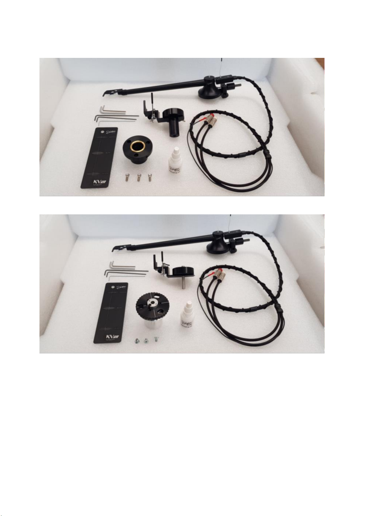
1. Box Contents:.............................................................................................................................................5
2. Unpacking..................................................................................................................................................5
II. Setting Up the Tonearm
1. Install the Tonearm Base ...........................................................................................................................7
1.1. Installing Tonearm Base with Screws.................................................................................................7
1.2. Installing Tonearm Base without Screws............................................................................................9
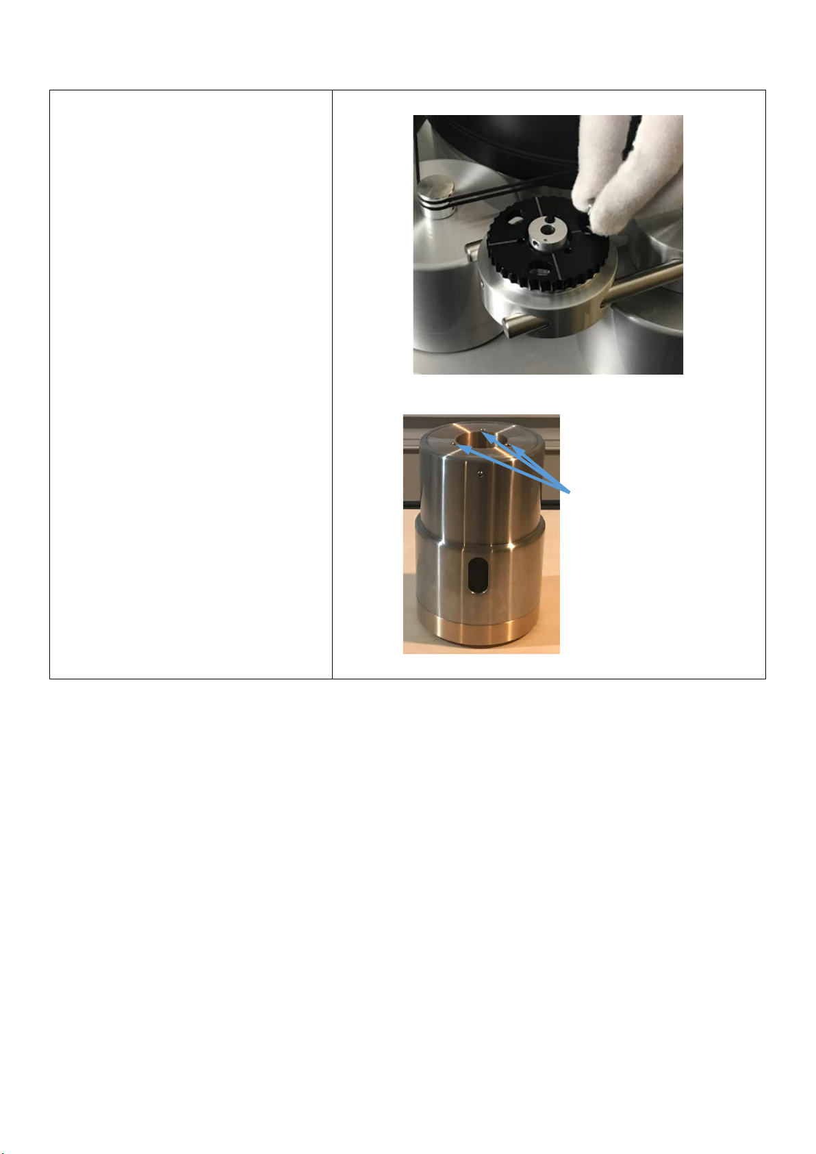
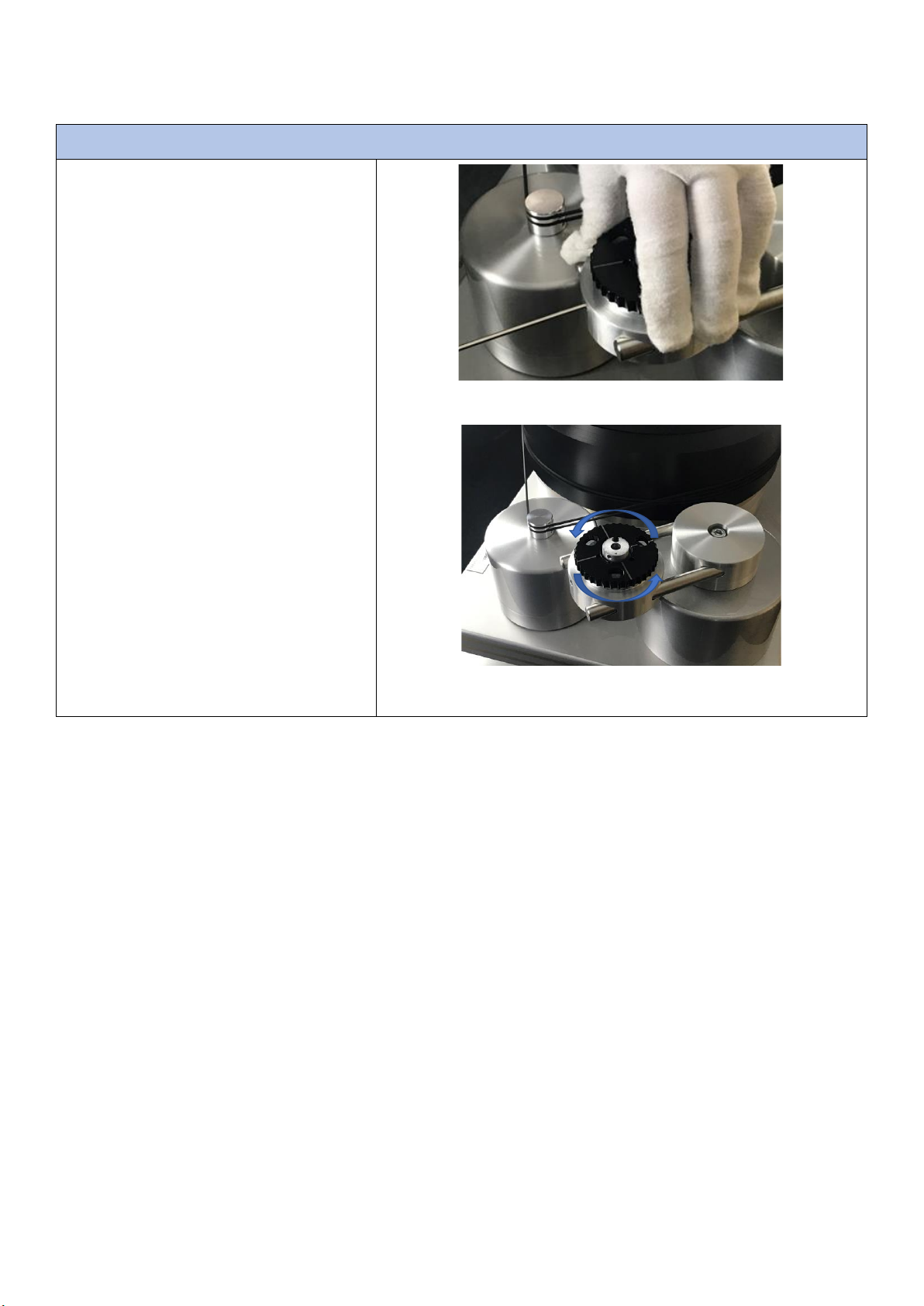
2. Placing the Sleeve....................................................................................Error! Bookmark not defined.
3. Adding Damping Oil................................................................................................................................14
4. Mounting a Cartridge...............................................................................................................................15
5. Installing the Tonearm Head....................................................................................................................16
5.1. Adding the Tonearm Head................................................................................................................16
5.2. Positioning the Tonearm Wire Cable Block .....................................................................................17
6. Adjusting Tracking Force........................................................................................................................19
7. Adjusting VTA.........................................................................................................................................20
7.1. Adjusting VTA on the KV12.............................................................................................................20
7.2. Adjusting VTA on the KV12-VTA ....................................................................................................20
8. Adjusting Geometry.................................................................................................................................21
9. Adjusting Azimuth...................................................................................................................................21
10. Adjusting Anti-Skate (Bias).................................................................................................................21
11. Setting Tonearm Wire Loop ................................................................................................................23
III. Maintaining Your Tonearm
1. Cleaning Your Tonearm ..........................................................................................................................23
2. Maintaining Your Tonearm .....................................................................................................................23
IV. Warranty

J.Sikora –Standard MAX Turntable Manual
4 © 2021 Notable Audio Products | www.notableaudio.com
I. General Information
The J.Sikora tonearms are a unipivot design that is the first to use aramid fiber for the Arm Wand. Aramid is
very light, stiff, and resistant to resonances. This makes it an ideal material for the production of the Wand’s
conical tube. Using aramid fiber reflects J.Sikora’s overarching philosophy of combining unique properties of
various materials such as aluminum, bronze, cast iron, and steel to maximize vibration control and stability.

J.Sikora –Standard MAX Turntable Manual
5 © 2021 Notable Audio Products | www.notableaudio.com
1. Box Contents:
- 1 x Tonearm with integral Tonearm Wire
- 1 x Tonearm Base
- 1 x Collar (with VTA adjustment only for the KV12-VTA model)
- 1 x set of Wrenches
- 1 x jar of J.Sikora Damping Oil
- 2 x Counterweights
- 1 x set of 3 Mounting Screws
- 1 x Alignment Protractor
2. Unpacking
Your tonearm and accessories ship in one wooden box. You can order J.Sikora tonearms with the natural
yellow Arm Wand or a black painted Arm Wand.
KV12-VTA Tonearms in Natural and Black
Note. Like all tonearms, the KV12 is a delicate, high-precision instrument and should be handled with
care. In particular, the Tonearm Wires are very delicate, so please use caution.

J.Sikora –Standard MAX Turntable Manual
6 © 2021 Notable Audio Products | www.notableaudio.com
Carefully remove all of the contents of the box and place them in a safe and convenient location.
KV12 tonearm set
KV12-VTA tonearm set

J.Sikora –Standard MAX Turntable Manual
7 © 2021 Notable Audio Products | www.notableaudio.com
II. Setting Up the Tonearm
To mount the KV12 or KV-12-VTA on any J.Sikora turntable, you won’t need any additional accessories. For
the J.Sikora Initial, Initial MAX, Standard, and Standard MAX turntables, the Tonearm will fit in the Universal
Armboard without needing any adapters (see the manuals for those tables for more details). For the J.Sikora
Reference turntable, you will need to order an Arm Tower with a J.Sikora.
When mounting a J.Sikora Tonearm on another manufacturer’s turntable, you will need the Armboard cut
for a “Kuzma™” pattern. In terms of height, the clearance between the top edge of the platter and the
tonearm mounting base should be a minimum of 50mm.
1. Install the Tonearm Base
The first step in installing the Tonearm is to insall the Tone Arm Base.
1.1. Installing Tonearm Base with Screws
For all non-J.Sikora turntables, the
J.Sikora Reference turntable, and as an
optional method on the Initial and
Standard series turntables, you will use
the supplied Screws (3) and Wrench to
secure the Base to the turntable’s
Armboard (see your turntable
manufacturer’s manual for more
detailed instructions).
KV12 tonearm base
KV12-VTA tonearm base
Insert a KV12-VTA Base in a J.Sikora Universal Armboard

J.Sikora –Standard MAX Turntable Manual
8 © 2021 Notable Audio Products | www.notableaudio.com
Inserting Screws through KV12-VTA Base and into Arm Pod
J.Sikora Reference Arm Tower
Holes for KV12
Tonearm Base
Screws

J.Sikora –Standard MAX Turntable Manual
9 © 2021 Notable Audio Products | www.notableaudio.com
1.2. Installing Tonearm Base without Screws
For the J.Sikora Initial and Standard
series turntables only, you have the
option of using the set screw on the side
of the Arm Pod instead of the Tonearm
screws to secure the Tonearm.
While this method does not have same
security as using the three larger
Tonearm Screws, it does provide extra
flexibility in adjusting your Tonearm. By
slightly loosening the Set Screw, you can
rotate the Tonearm Base with the Arm
Pod. This can be very helpful when
setting the proper geometry.
Using Armpod’s Sets Screw to secure KV12-VTA Tonearm Base
Tonearm Rotates within Arm Pod
KV12-VTA Tonearm Base

J.Sikora –Standard MAX Turntable Manual
10 © 2021 Notable Audio Products | www.notableaudio.com
2. Placing the Sleeve
Place the Tonearm Sleeve into the hole of the Tonearm Base.
2.1. Identifying Parts
The images to the right identify the
parts of the KV12 and KV12-VTA Bases
and Sleeves.
KV12 Arm and Base
KV12-VTA Arm and Base
Set
Screw
Sleeve
Base
Set
Screw
Sleeve
Base
VTA
Knob

J.Sikora –Standard MAX Turntable Manual
11 © 2021 Notable Audio Products | www.notableaudio.com
2.2. Loosen Set Screw
For both arms, the Sleeve is held in
place by a Set Screw on the Base. You
will use the supplied Wrench to loosen
the Set Screw
For the KV12 Base, the Set Screw is on
the side of the Base.
The Set Screw for the KV12-VTA Base is
located on the side of the central
column of the Base. As packaged, the
Base is set to the minimum height
position, so the Set Screw is not
visable. To loosen the Set Screw, you
will need to turn the VTA Knob until
the Set Screw is visable.
KV12 Base with Wrench
KV12-VTA Base in Minimum
Height Position
KV12-VTA Base with the
Central Column Raised
KV12-VTA Base with Wrench
Set
Screw
Set
Screw

J.Sikora –Standard MAX Turntable Manual
12 © 2021 Notable Audio Products | www.notableaudio.com
2.3. Install Sleeve
Now that the Set Screw is loose, slide
the Sleeve into the Base. If there is
resistance, then you need to further
loosen the Set Screw.
Placing Sleeve into Base –KV12
Placing Sleeve into Base –KV12-VTA

J.Sikora –Standard MAX Turntable Manual
13 © 2021 Notable Audio Products | www.notableaudio.com
2.4. Secure Sleeve Position
With the Sleeve in place, re-tighten
the Set Screw so that the Sleeve is
locked in place.
If you need to adjust the position of
the Sleeve later, you must first loosen
the Set Screw again so that the Sleeve
can rotate freely within the the Base.
Securing Sleeve –KV12
Securing Sleeve –KV12-VTA

J.Sikora –Standard MAX Turntable Manual
14 © 2021 Notable Audio Products | www.notableaudio.com
3. Adding Damping Oil
Gently squeeze the bottle of Damping Oil
into Oil Pan of the Sleeve. Fill the Pan up to
the horizontal Fill Line marked on the side
of the Pan. If you fill over the line, Oil may
overflow the pan when you add the
Tonearm Head (Step 5.1).
Adding Oil
Oil Fill Line (Do Not Go Over)
Warning. The Damping Oil may leave stains which are difficult to remove. Follow the next step with
caution.

J.Sikora –Standard MAX Turntable Manual
15 © 2021 Notable Audio Products | www.notableaudio.com
4. Mounting a Cartridge
We suggest that you mount your
cartridge to the Tonearm’s Headshell
prior to placing the Tonearm Head on
the Tonearm Base.
Connect the pins according to the
colors. Refer to your cartridge's
instruction manual.
Tonearm Headshell and Tonearm Wire Leads
Cartridge Mounted to Headshell
Headshell
Leads

J.Sikora –Standard MAX Turntable Manual
16 © 2021 Notable Audio Products | www.notableaudio.com
5. Installing the Tonearm Head
In this step, you will add the Tonearm Head and place the Tonearm Cable Wire Block. This step is the same
for both the KV-12 and the KV12-VTA.
5.1. Adding the Tonearm Head
Carefully lower the Tonearm Head onto
the Tonearm Base. The Pin (point) on
the underside of the Head should fit into
the indention on the metal shaft in the
middle of the Base’s Pan.
Lowing Tonearm Head into Tonearm Base
Assembled Arm

J.Sikora –Standard MAX Turntable Manual
17 © 2021 Notable Audio Products | www.notableaudio.com
5.2. Positioning the Tonearm Wire Cable Block
The KV12 and KV12-VTA use a single run
of Tonearm Wire that extends from the
Cartridge Leads, through the inside of
the Arm Wand, out of the top of the
Tonearm Head. The Wire then loops
down into the Connection Block and
then out externally in a shielded sheath
to the Connect Jacks and Ground.
Parts of Tonearm Wire
To protect the fragile Tonearm Wire in
transport, the Connection Block is
screwed down to the Storage Pin on the
back of the Tonearm Head.
Before using the turntable, you will
need to slide the Connection Block back
off the Storage Pin and slide the
Connection Block over the Support Pin
located on the side of the Head (see the
next step for details). This removes the
weight on the Connection Block and
external Wire from the Arm. Move the
Tonearm Block back to the Storage Pin
whenever you are done using the
turntable in order to protect the loop of
the Tonearm Wire.
Shipping Location of Connection Block
Support Pin
Cable Loop
Cable
Leads
External
Segment
Jacks &
Ground
Connection
Block
Arm Wand
Connection
Block
Storage
Pin
Support
Pin

J.Sikora –Standard MAX Turntable Manual
18 © 2021 Notable Audio Products | www.notableaudio.com
To move the Connection Block, use the
supplied Wrench to loosen the Set
Screw at the top of the Block just
enough so the Block can slide freely on
the Storage Pin.
Using Screw to Loosen Block Set Screw
Next slide the Connection Block over the
Support Pin and re-tighten the Set
Screw to secure the Block in place.
Securing Block on Suport Pin

J.Sikora –Standard MAX Turntable Manual
19 © 2021 Notable Audio Products | www.notableaudio.com
6. Adjusting Tracking Force
The Tonearm ships with two
threaded Counterweights for
adjusting tracking force required for
your cartridge (see your cartridge’s
manual this specification).
Twist one or both of the
Counterweighs onto the threaded
rod that extends out the back of the
Tonearm head until you achieve the
proper weight for your cartridge.
Counterweighs
Location for Counterweighs
Treaded Rod
For Weights

J.Sikora –Standard MAX Turntable Manual
20 © 2021 Notable Audio Products | www.notableaudio.com
7. Adjusting VTA
The Vertical Tracking Angle (VTA) is the angle of the Cartridge’s cantilever and the surface of the record.
The correct height of the Tonearm will differ for each cartridge. In this step, you will learn how to adjust
the VTA for the KV12 and KV12-VTA Tonearms.
7.1. Adjusting VTA on the KV12
To adjust the VTA on the KV12, use your
hand to hold the Sleeve in place. Then
slightly loosen to the Set Screw with the
supplied wrench until the Sleeve can
slide freely. You may now raise or lower
the Sleeve as needed. Finally, tighten
the Set Screw and re-check for proper
VTA.
Do this incrementally until you reach the
proper VTAI.
KV12 Base and Sleeve
7.2. Adjusting VTA on the KV12-VTA
The KV12-VTA uses a VTA Knob that
allows you set the VTA “on-the-fly”
while listening to records in order to
more precisely lock in the proper VTA.
To adjust the VTA on this arm, simply
turn the Knob to raise or lower the arm.
A full turn of the VTA knob results in a 4
mm in a change in height. Turning the
Knob from the white line to the next
white line on the knob results in a 1 mm
change.
KV12-VTA Collar
1 mm VTA Increment Lines
Set
Screw
Sleeve
Base
VTA
Knob
1 mm
Lines
Table of contents