Sound Devices MD-4 User manual
®
MD-4
Mic/Line Input & Line Output Dante Interface
User Guide

Sound Devices, LLC
E7556 Road 23 and 33
Reedsburg, Wisconsin 53959 USA
Direct: +1 (608) 524-0625
Toll Free: (800) 505-0625
Fax: +1 (608) 524-0655
www.sounddevices.com
Legal Notices
Product specications and features are subject to
change without prior notication.
Copyright © 2017 Sound Devices, LLC.
All rights reserved.
This product is subject to the terms and conditions
of a end-user license agreement provided in this
guide, and may be used in accordance with the
license agreement.
This document is protected under copyright law.
An authorized licensee of this product may repro-
duce this publication for the licensee’s own per-
sonal use. This document may not be reproduced
or distributed, in whole or in part, for commercial
purposes, such as selling copies or providing edu-
cational services or support.
This document is supplied as a technical guide.
Special care has been taken in preparing the in-
formation for publication; however, since product
specications are subject to change, this docu-
ment might contain omissions and technical or ty-
pographical inaccuracies. Sound Devices, LLC does
not accept responsibility for any losses due to the
user of this guide.
Trademarks
The “wave” logo is a registered trademark of Sound
Devices, LLC. Dante is a trademark of Audinate
Pty Ltd. All other trademarks herein are the prop-
erty of their respective owners.
WEEE Statement
If you wish to discard a Sound Devices
product in Europe, contact Sound Devices
(Germany) for further information.
Revision History
This table provides the revision history for this guide.
Rev# Date Firmware
Version
Description
1-A April 2017 v03 Initial release
1-B May 2017 v03 Added Declaration of
Conformity info.
This document is distributed by Sound Devices,
LLC in online electronic (PDF) format only. E-pub-
lished in the USA.
MD-4 User Guide • May 4, 2017

3
Sound Devices, LLC
Table of Contents
MD-4
Front Panel Descriptions ..........................5
Back Panel Descriptions ...........................6
Overview .......................................7
Applications ....................................7
Inputs and Outputs
Mic/Line Inputs ..................................9
Microphone Preamplifiers ......................9
Line-Level Inputs ..............................9
Input Meters and Indicators .....................9
Analog Input Reference Level ...................9
Input Electrical Characteristics ...................9
Selecting an Input for Control ...................9
Input Gain Control ...........................10
P48 Phantom Power ..........................10
High-Pass Filter (HPF) ..........................10
Line Outputs ...................................11
Electrical Connection ..........................11
Analog Reference Level .......................11
Assigning Dante Channels to Outputs............11
Input and Output Monitoring ....................12
Metering ....................................12
Phones / Monitor Output ......................12
Selecting Monitor Sources......................12
Mono / Stereo Metering .......................12
Powering and Mounting
Powering the MD-4 .............................13
AC Mains Power .............................13
DC Power ...................................13
Powering On ................................13
Rack Mounting .................................13
Dante
Dante Interconnection ...........................15
Subscriptions: Establishing
Connections..................................15
Ethernet and Dante Status LEDs ................15
How to Identify a Specific MD-4 ................15
IP Address Assignment ........................15
Optimizing Network
Performance .................................16
Firmware Update Procedure .....................17
Dante Firmware Update .......................17
Specifications
MD-4 Specifications .............................19
Software License
Declaration of Conformity........................22

5
MD-4
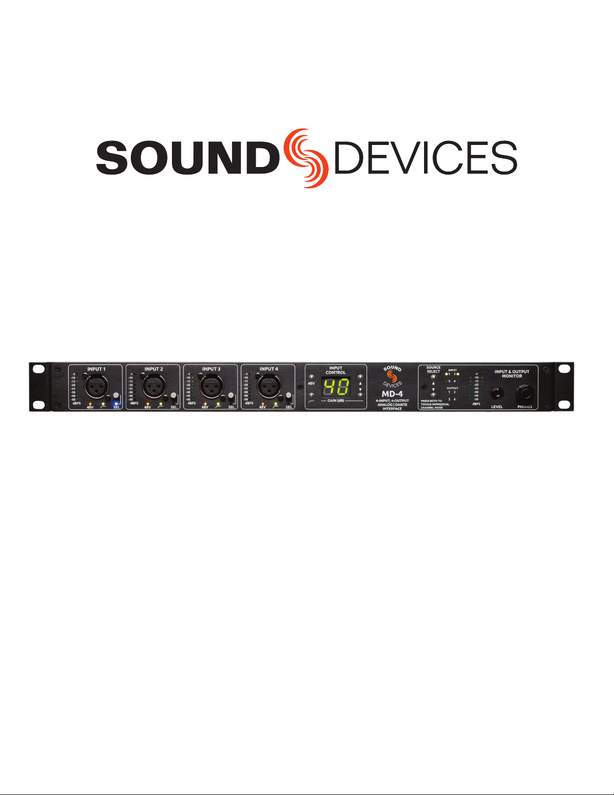
1) Input Level Meter LEDs
Indicates input signal level in dBFS
2) Input Connector
XLR-3 accepts balanced or unbalanced micro-
phone or line-level sources; friction-t, secure
connection
3) Phantom Power LED
When illuminated, indicates phantom power is
active
4) High-Pass Filter LED
When illuminated, indicates high-pass lter is
active
5) Select Button and SEL LED
Press to select an input for control at the Input
Control. The SEL LED illuminates to indicates
input selection. Hold to send input to headphone
monitor.
6) Phantom Power Control
Toggles 48 V phantom power for a selected input
7) High-Pass Filter Control
Toggles high-pass lter for a selected input
8) Gain Display
Numeric display indicates the gain setting, in dB,
for a selected input
9) Input Gain Control
Buttons to increase or decrease gain level of a
selected input. 0 dB is unity, 70 dB is maximum
10) Monitor Source Selection
Buttons to select input source available for
headphone monitoring. Selects among inputs or
outputs
11) Source Selection LEDs
Illuminates adjacent to the selected source for
headphone monitoring.
12) Monitor Meter
8-segment LED indicates the signal level in dBFS
of the selected monitor source
13) Headphone Level Control
Recessable rotary control for headphone level
control
14) Headphone Output Connector
1/4-inch headphone jack to connect headphones.
Wired tip-left, ring-right, sleeve-common ground
Front Panel Descriptions
1
2
3 4 5 7 11 13 14
6 8 10 129
User Guide
6Sound Devices, LLC
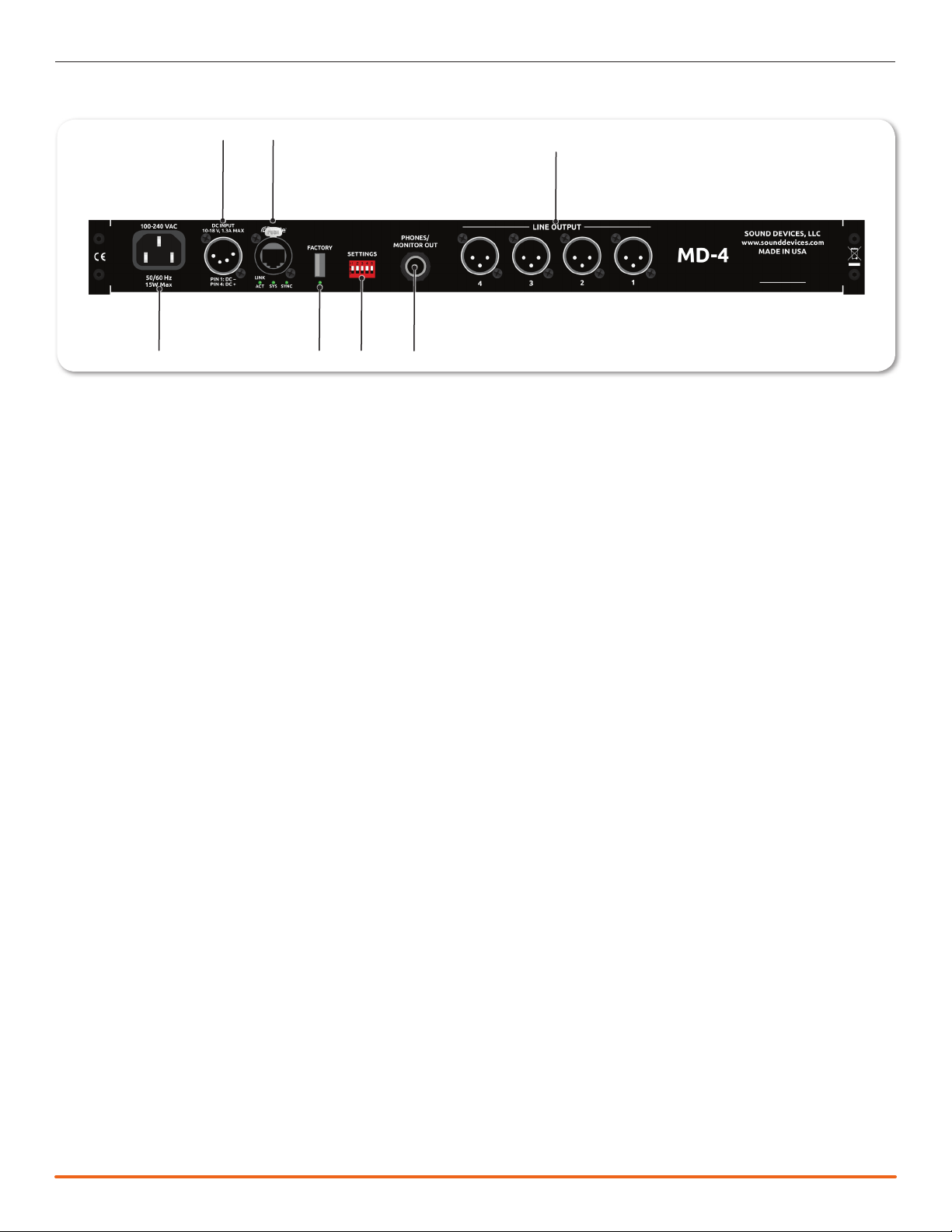
1) AC Power Input
Accepts 100-240 VAC, 50/60 Hz
2) DC Power Input
XLR-4 connector for secondary power input,
accepts 10-18 VDC.
3) Dante RJ-45 Ethernet Connection
Connection to and from a Dante audio-over-Ether-
net network
4) Factory
USB A-type connector for updating MD-4 operating
rmware
5) Settings DIP Switches
Switches controlling input and output level ref-
erences. (See Analog Reference Level and Line
Outputs, respectively)
6) Phones/Monitor Output
1/4-inch headphone output wired tip-left, ring-
left, sleeve-ground. Identical signal as front panel
headphone jack. Output is muted when front
panel connection is in use. Can also be used to
drive unbalanced line inputs, such as powered
loudspeakers.
7) Line Outputs
Balanced XLR line output connections. Signal
source is assigned over Dante through Dante
Controller software, or equivalent.
Back Panel Descriptions
1
2
456
37
Table of contents
Other Sound Devices Accessories manuals


