3
ENGLISH
1�5 UPDATE OF INSTRUCTION MANUAL
This instruction manual is consistent with the technical
knowledge available at the time of introduction of the
stove for marketing.
Stovessold withallindispensable technicaldocumentation
cannot be recognised by JØTUL as non-compliant with
requirements in relation to potential modifications or the
application of new technologies in equipment introduced
onto the market at a later time.
1�6 GENERAL INFORMATION
InformatIon
During exchange of information with the stove’s
manufacturer, providethe serialnumber andidentification
data in the appropriate data sheet.
LIabILIty
Delivery of this instruction manual releases JØTUL from
any civil or penal liability in the event of damage or injury
arising as a result of failure to adhere, even partially, to
the guidelines and instructions given in this document.
JØTUL also bears no liability in the case of inappropriate
or improper use of the equipment, in the case of
unauthorised modification and/or repair, as well as in
the case of use of spare parts that are no original or not
suitable for the stove model being the subject of this
instruction manual.
ExtraordInary maIntEnancE
Maintenance activities must be performed by qualified
personnel with knowledge on how to perform works on
the stove model to which this instruction manual pertains.
obLIgatIons rELatEd to InstaLLatIon works
JØTUL is not liable for any works related to stove
installation.
• Only the fitter is responsible for checking whether
there is an inlet for combustion air and for checking its
cross-section in accordance with applicable standards,
as well as for compliance of proposed solutions
concerning stove installation.
• The stove and its installation must also fulfil all safety
standards defined by detailed regulations binding in the
country where the stove is installed.
• The fitter must have the qualifications required by the
European Union directive on renewable energy sources.
UsE
Similarly to the requirements given in this instruction
manual, use of the equipment must be compliant with all
safety standards defined by detailed regulations applicable
in the country where the equipment is installed..
1�7 MAIN REFERENCE SAFETY
STANDARDS THAT MUST BE
ADHEREDTO
A) Directive 2006/95/EC: “Harmonisation of the laws
of Member States relating to electrical equipment
designed for use within certain voltage limits”.
B) Directive2004/108/EC: “Approximationofthe laws
of the Member States relating to electromagnetic
compatibility”.
C) Directive 89/391/EEC: “Introduction of measures to
encourage improvements in the safety and health of
workers at work”.
D) Directive 89/106/EEC: “on the approximation of
laws, regulations and administrative provisions of the
Member States relating to construction products”.
E) Directive 85/374/EEC: “on the approximation of
the laws, regulations and administrative provisions of
the Member States concerning liability for defective
products”.
F) Directive 1999/5/EC: “on radio equipment and
telecommunications terminal equipment and the
mutual recognition of their conformity”.
1 INTRODUCTION
Jøtul heating equipment (hereinafter referred to as pellet
stoves) are designed and installed in accordance with
the safety regulations defined in the relevant European
directives.
This instruction manual is intended for users, fitters and
maintenance technicians of stoves. In the case of doubts
concerning the content of this instruction manual and
to obtain explanations, contact the manufacturer or
authorised seller, specifying the number of the section to
which the question pertains.
Printing, translation and duplication of this document,
in part or entirety, requires written consent from the
JØTUL company.
Technical information, graphical representations and
detailed drawings given in this instruction manual may not
be made available to third parties.
If a fitter has not fully understood the contents of this
instruction manual, they should not service the stove. In
the case of doubts, ask a technician authorised by JØTUL
for assistance in every instance.
JØTUL reserves the right to introduce technical and/or
functional changes to the stove at any time without advance
notice.
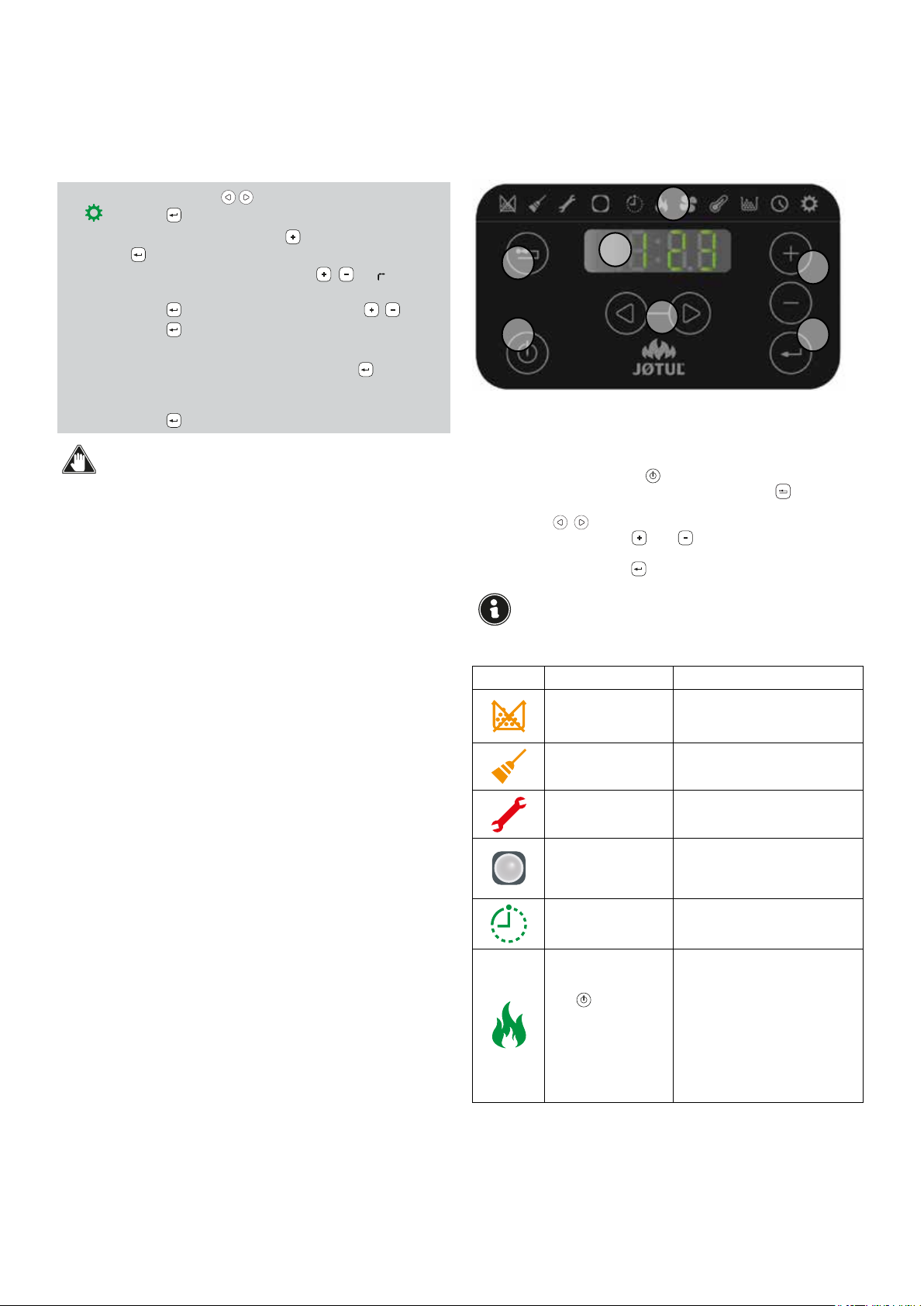
1�1 SYMBOLS
In this instruction manual, the most important guidelines,
instructions or recommendations are marked with one of
the following symbols:
Guidelines concerning proper use of the stove and
responsibilities of persons performing activities on the
stove�
Guidelines concerning safe use and operation�
1�2 USE
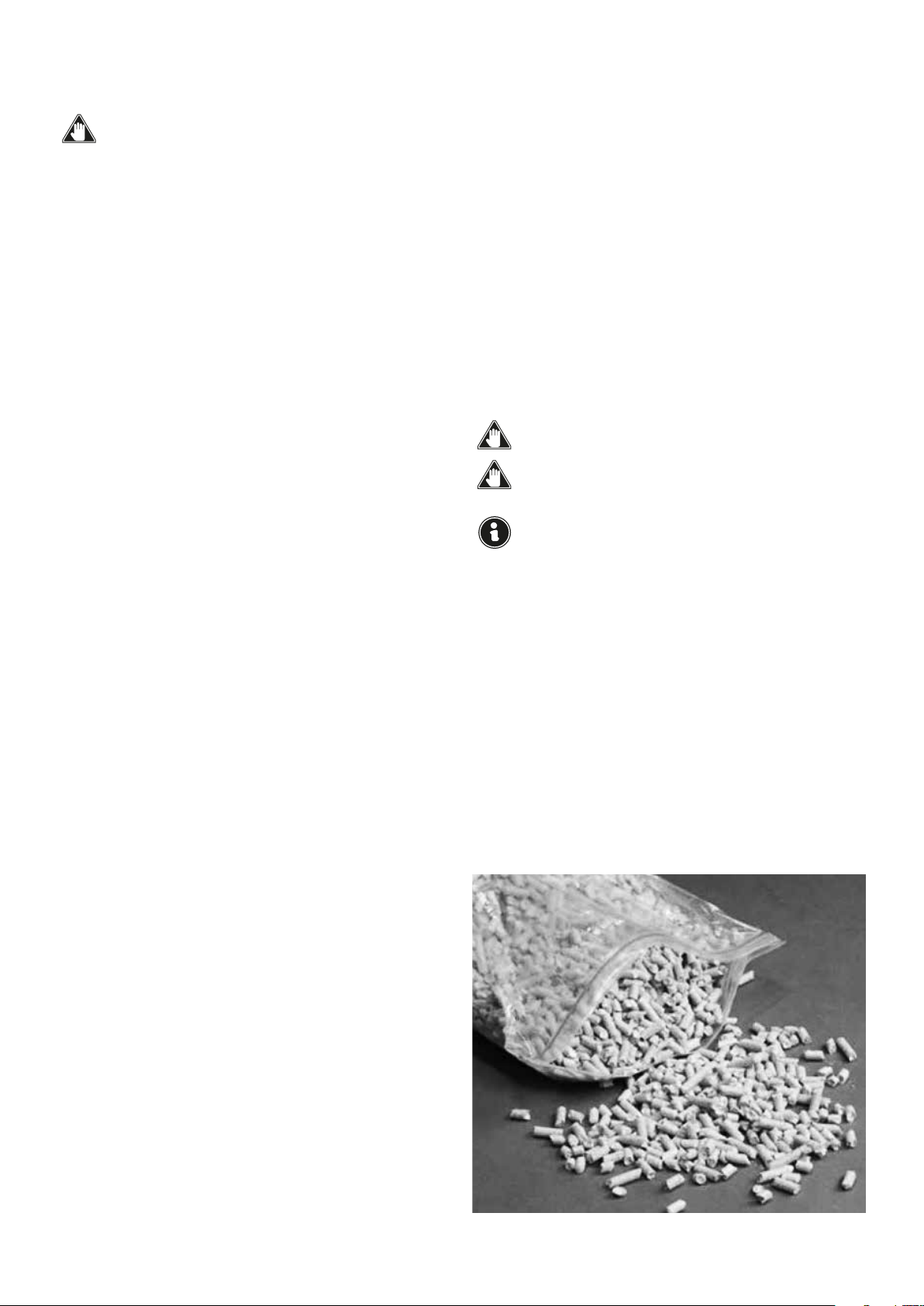
The JØTUL stove is intended for heating of the interior of
a house� It is technologically advanced and fired with wood
pellet in automatic work mode� Combustion is activated
only when the stove’s door is closed� It is strictly prohibited
to open the door while the stove is working�
The only method of use and configuration of the stove
permitted by the manufacturer is use in compliance with
the purpose and configurations given below� The heating
equipment may not be used in a manner that is non-
compliant with the given instructions�
1�3 PURPOSE AND CONTENT OF THE
INSTRUCTION MANUAL
The purpose of this instruction manual is to provide
the fitter with information and basic rules for proper
installation and maintenance. Precise adherence to the
instructions provided in this manual guarantees a high
level of safety and durability of the stove.
1�4 STORAGE OF THE INSTRUCTION
MANUAL
storagE and browsIng
The instruction manual must be stored with due diligence
and must be available for consultation by the user and by
specialists concerned with installation and maintenance.
The installation instruction manual is an integral part of
the stove.
dEstrUctIon or Loss
If necessary: request a new copy from your JØTUL
salesperson.
rEsaLE of stovE
In the case of resale of the stove, the user is obliged to
transfer the instruction manual to the new user.