J. W. Davis & Company DA-120M User manual

NEWTECHNOLOGY OLDRELIABILITY
J.W. Davis & Company •
3030 Canton Street • P.O. Box 710219 • Dallas, Texas 75371-0219
Sales 800-527-5705 • Fax 800-388-9106 • Corp 214-651-7341 • Fax 214-939-0328 • [email protected] • www.jwd.com
DA-120M Master Series Amplifier
USER’S MANUAL
The Mark of the Professional...
090705122
- Unpacking/Inspection Procedures - PA Speaker Layout
- Schematic for Input Modules 1- 4
- Technical Specifications
- Circuit Board Level Settings
- Polarity
- Power Loss in Long Lines
- Back Panel Detail
- Product Description
2
2
3
5
8
9
10
12
12
13
14
15
- Product Features
- Schematic for Input Modules 5-6
- Schematic for Chassis Board
I
II
III
IV
V
VI . . . . . . . . . . . .
. . . .
. . . . . . . . . . . . . . . . . .
. . . . . . . . . . . . . . . .
. . . . . . . . . . . . . . . . . .
. . . . . . . . .
VII
VIII
IX
X
XI
XII . . . . .
. . . . . . . . . . . . . .
. . . . . . . . . . . . . . . . . . . . . . . .
. .
. .
. . . . . . . .

The Mark of the Professional...
NEWTECHNOLOGY OLDRELIABILITY
J.W. Davis & Company 3030 Canton Street • P.O. Box 710219 • Dallas, Texas 75371-0219
Sales 800-527-5705 • Fax 800-388-9106 • Corp 214-651-7341 • Fax 214-939-0328 • [email protected] • www.jwd.com
•
This unit was carefully checked and packed before leaving the factory. However, the shipping con-
tainer and unit should be inspected for indications of improper handling. If the unit has been damaged
in transit, make an immediate claim to the carrier for their inspection. Returning the freight to J. W. Davis
& Company will void your claim with the carrier.
The features and benefits listed below make this a unique amplifier, designed with the user’s needs in
mind, to be a product that is universal and fits many applications without modifications or additional equip-
ment.
2
I - UNPACKING AND INSPECTION PROCEDURES
II - FEATURES
WARNING: TO REDUCE THE RISK OF FIRE OR ELECTRICAL SHOCK, DO NOT
EXPOSE THIS UNIT TO RAIN OR MOISTURE.
WARNING: TO REDUCE THE RISK OF ELECTRICAL SHOCK, DO NOT REMOVE
THE COVER. NO USER SERVICEABLE PARTS INSIDE. REFER SERVICING TO
QUALIFIED SERVICE PERSONNEL.
WARNING: DO NOT CUT OR REMOVE THE GROUND PIN ON THE AC POWER
CABLE. DO NOT USE AC TWO PIN ADAPTER UNLESS IT IS GROUNDED BY AN
EXTERNAL GROUND WIRE. CHECK THE AC WALL RECEPTACLE TO CONFIRM
THE PROPER GROUND IS PRESENT.
7 Major Application Interfaces
•
6 Switchable Microphone/AUX Inputs
•
15 Special Signal Inputs
•
7 Signal Outputs
•
Multiple Music-On-Hold Options
•
24 VDC Alternate Power Source
•
120 Watts RMS Power
•
8-Ohm, 25 and 70 Volt System Outputs
•
A switch to activate the 400Hz roll off circuit to protect horn drivers
•
Tape out for recording
•
Pre-out, Main-In for insertion of signal conditioning equipment such as equalization
•
Booster out provides a signal for power amplifiers to expand the system
•
FIVE-YEAR WARRANTY
•

The third dip switch (designated “J”) activates the microphone
XLR input. Do not use the phoenix-type microphone input at the
same time as this will degrade the signal.
The front panel has nine controls: Six front panel volume controls (to individually control dip switchable
microphone or auxiliary inputs located on the back panel), a bass and a treble control, plus a master
volume control. In addition, the power switch and LED signal overload indicators are located on the front
panel for easy access.
The first dip switch shown in Figure 1 (designated “AUX”) activates the auxiliary input. This aux input
consists of two RCA jacks (marked “AUX” with an input number and “unbalanced”) that electronically
combine stereo or two-channel audio for a mono signal. To input
a single mono signal, either RCA jack may be used.
The Mark of the Professional...
NEWTECHNOLOGY OLDRELIABILITY
J.W. Davis & Company 3030 Canton Street • P.O. Box 710219 • Dallas, Texas 75371-0219
Sales 800-527-5705 • Fax 800-388-9106 • Corp 214-651-7341 • Fax 214-939-0328 • [email protected] • www.jwd.com
•
3
The back panel contains the six microphone/auxiliary input modules matching the six front panel
volume controls. All are similar to Figure 1 except for input module 5 which has two additional RCA jack
inputs for CD or DVD .
The fourth dip switch (designated “Phantom”) activates the phantom power needed for condenser
microphones. If the phantom power is left on, it will not harm the dynamic microphones but should be
turned off for safety measures when not in use.
The second dip switch (designated “T”) activates the phoenix-
type microphone input. Do not use the XLR connector at the
same time, as this will degrade the signal.
III - DESCRIPTION
The JWD Master Series of monaural amplifiers provide the combination of interface, signal control
and extended mixer capacity required by professional audio system integration. In addition to traditional
commercial sound applications such as paging and background music, the Master Series extends the
scope of capabilities to include integration with telephone communications, audio-visual, security, sound
masking and digital devices that previously have been available only in more complex modular amplifiers.
All features are inclusive without requiring additional accessories or modifications.
Three additional dedicated inputs with volume controls are located on the back panel. (The Master Vol-
ume Control or the Bass and Treble Controls do not affect the following three inputs.)
(1) Telephone Page input that accepts the signal directly from the page port out on the
telephone system.
(2) Music-On-Hold (built in) one-watt amplifier that provides music and information to
the telephone hold system. The same infromation may be routed to the main amplifier for
distribution to the entire sound system via input 5.
(3) System OverRide (“SOR”) input default setting is for sound masking. This input is not
affected by the tone controls or any other function of the amplifier. The sound masking may
be equalized before using the other amplifier functions. However, the input also may be
changed by a jumper on the circuit board to become a priority input for the system.
Figure 1

The Mark of the Professional...
NEWTECHNOLOGY OLDRELIABILITY
J.W. Davis & Company 3030 Canton Street • P.O. Box 710219 • Dallas, Texas 75371-0219
Sales 800-527-5705 • Fax 800-388-9106 • Corp 214-651-7341 • Fax 214-939-0328 • [email protected] • www.jwd.com
•
4
NOTE: If the Amplifier is frequently moved to different locations, or used as a
portable system, the XLR connectors should be used. The action of plugging
and unplugging the connector maintains a good connection. If the amplifier
is installed in a permanet location, the phoenix-type screw terminals should be
used for a better long-term connection.
Paging with VOX muting may be accomplished either from microphone one
input or through the telephone input, a feature desirable in installations such as
hospitals, airports and auto dealerships where paging may be required from
multiple locations.
A separate, internal, 1-watt amplifier is used to provide the music-on-hold functions which permits close
control of volume levels. The music-on-hold RCA-type input shown in Figure 2 allows the signal from
music, tape messages, company advertisements or other sources to feed the music-on-hold amplifier.
The output also may be routed to include the main amplifier for general distri-
bution using the switch in Figure 2.
Figure 2
A wide range of background music and audio/visual programming applications are supported through
the CD/DVD input and the six AUX inputs. For applications requiring recording of program material, a
special tape-out jack is available.
An equalizer or other signal modifying devices may be easily inserted by an external pre-amp, input-
output jack. An external dip switch for phantom power eliminates the need to remove cover.
A master volume control is provided for overall control of the microphone and auxiliary outputs. Bass and
treble controls permit adjustment of voice and music output.
Applications such as priority signaling and sound masking that must not be interrupted by the regular
functions of the amplifier are possible through the dedicated System OverRide input control that is
independent of the master, bass or treble controls.
Paging horn protection from damage against overdriving the lower frequencies is provided by 400Hz
high pass filter.
Installation expansion requiring greater power is accomplished through a booster output jack which
allows the signal from the DA-120M to be connected to the input of an additional amplifier.
The DA-120M may be rack or wall mounted using optional accessory kit RAK-120A/M, or WM-120M.
VOX muting is available for MIC 1 and System OverRide by activation at the board level.

The Mark of the Professional...
NEWTECHNOLOGY OLDRELIABILITY
J.W. Davis & Company 3030 Canton Street • P.O. Box 710219 • Dallas, Texas 75371-0219
Sales 800-527-5705 • Fax 800-388-9106 • Corp 214-651-7341 • Fax 214-939-0328 • [email protected] • www.jwd.com
•
IV - BACK PANEL DETAIL
5
(9) Input 2 XLR input jack accepts balanced low impedance signal from microphones, mixers, wireless micro-
phone receivers and equipment with compatible signals. The input is rated at 150Ω, 1mV.
INPUT 2
(2) Input 4 terminal strip input accepts balanced low Impedance signal from microphones, mixers, wireless
microphone receivers and equipment with compatible signals. The input is rated at 150Ω, 1mV.
(3) Input 4 dip switch allows four selections: auxillary (AUX), screw terminal (T), XLR-F (J) and 17VDC phantom
power (PHANTOM).
Input 4 XLR input jack accepts balanced low impedance signal from microphones, mixers, wireless micro-
phone receivers and equipment with compatible signals. The input is rated at 150Ω, 1mV.
(1)
INPUT 4
(7) Input 3 terminal strip input accepts balanced low impedance signal from microphones, mixers, wireless
microphone receivers and equipment with compatible signals. The input is rated at 150Ω, 1mV.
(8) Input 3 XLR input jack accepts balanced low impedance signal from microphones, mixers, wireless micro-
phone receivers and equipment with compatible signals. The input is rated at 150Ω, 1mV.
(6) Input 3 dip switch allows four selections: auxillary (AUX), screw terminal (T),
XLR-F (J) and 17VDC phantom power (PHANTOM).
(5) Input 3 features two RCA jacks that electronically combine stereo or two-
channel audio for a mono signal. To input a single mono signal, either RCA
jack may be used. The input is rated at 47kΩat 100mV.
INPUT 3
(4) Input 4 features two RCA jacks that electronically combine stereo or two-
channel audio into a mono signal. To input a single mono signal, either RCA
jack may be used. The input is rated at 47kΩat 100mV.
(10) Input 2 terminal strip input accepts balanced low impedance signal from microphones, mixers, wireless
microphone receivers and equipment with compatible signals. The input is rated at 150Ω, 1mV.
(11) Input 2 dip switch allows four selections: auxillary (AUX), screw terminal (T), XLR-F (J) and 17VDC phantom
power (PHANTOM).
NOTE: Only one input
on the dip switch (Micro-
phone XLR, Microphone
Screw Terminal or Auxil-
iary) should be selected
at any given time. Se-
lecting more than one
input will cause a distor-
tion and a drop in the in-
put signal.
(12) Input 2 features two RCA jacks that electronically combine stereo or two-channel audio into a mono signal.
To input a single mono signal, either RCA jack may be used. The input is rated at 47kΩat 100mV.

The Mark of the Professional...
NEWTECHNOLOGY OLDRELIABILITY
J.W. Davis & Company 3030 Canton Street • P.O. Box 710219 • Dallas, Texas 75371-0219
Sales 800-527-5705 • Fax 800-388-9106 • Corp 214-651-7341 • Fax 214-939-0328 • [email protected] • www.jwd.com
•
6
INPUT 1
(17)
(18)
(19)
(20)
(21)
Input 5 XLR input jack accepts balanced low impedance signal from microphones, mixers, wireless
microphone receivers and equipment with compatible signals. The input is rated at 150Ω, 1mV.
Input 5 terminal strip input accepts balanced low impedance signal from microphones, mixers, wireless
microphone receivers and equipment with compatible signals. The input is rated at 150Ω, 1mV.
Input 5 dip switch allows four selections: auxillary (AUX), screw terminal (T), XLR-F (J) and 17VDC phan-
tom power (PHANTOM).
Input 5 features two RCA jacks that electronically combine stereo or two-channel audio into a mono signal.
To input a single mono signal, either RCA jack may be used. The input is rated at 47kΩat 100mV.
NOTE: If the Music-On-Hold is switched to main amp, no other inputs on Aux 5 can be used. The controls
for Input 5 on the front will apply. The MOH output will remain controlled by the volume control located at the
MOH input.
Input 5 has an additional input for DVD or CD. The input is rated at 47kΩ, 360mV.
(22)
(23)
Input 6 features two RCA jacks that electronically combine stereo or two-channel audio into a mono signal.
To input a single mono signal, either RCA jack may be used. The input is rated at 47kΩat 100mV.
Input 6 dip switch allows four selections: auxillary (AUX), screw terminal (T), XLR-F (J) and 17VDC phan-
tom power (PHANTOM).
(24) Input 6 terminal strip input accepts balanced low impedance signal from microphones, mixers, wireless
microphone receivers and equipment with compatible signals. The input is rated at 150Ω, 1mV.
(25) Input 6 XLR input jack accepts balanced low impedance signal from microphones, mixers, wireless
microphone receivers and equipment with compatible signals. The input is rated at 150Ω, 1mV.
(13)
(14)
Input 1 features two RCA jacks that electronically combine stereo or two-channel audio into a mono signal.
To input a single mono signal, either RCA jack may be used. The input is rated at 47kΩat 100mV.
Input 1 dip switch allows four selections: auxillary (AUX), screw terminal (T), XLR-F (J) and 17VDC phan-
tom power (PHANTOM).
(15)
(16)
Input 1 terminal strip input accepts balanced low impedance signal from microphones, mixers, wireless
microphone receivers and equipment with compatible signals. The input is rated at 150Ω, 1mV.
Input 1 XLR input jack accepts balanced low impedance signal from microphones, mixers, wireless
microphone receivers and equipment with compatible signals. The input is rated at 150Ω, 1mV.
INPUT 5
INPUT 6

NEWTECHNOLOGY OLDRELIABILITY
J.W. Davis & Company 3030 Canton Street • P.O. Box 710219 • Dallas, Texas 75371-0219
Sales 800-527-5705 • Fax 800-388-9106 • Corp 214-651-7341 • Fax 214-939-0328 • [email protected] • www.jwd.com
•
7
The Mark of the Professional...
(39)
(40)
(41)
Chassis Ground Terminal.
24VDC Power Input. The 24 VDC allows the amplifier to be used with emergency backup power supplies,
portable use or where 115VAC is not available.
Speaker Output Terminals. The available screw terminal outputs are 8Ω, 25V or 70V. Only one output should
be used at a time.
(37) High Pass Filter Switch. When the switch is in the ON position, the output signal will roll off frequencies of
400Hz and below. Eliminating the lower frequencies will help prevent damage to the voice coil (diaphram) of
horns.
(38) Receptacle for 115V Power Cable. Built-in 5A, 250V Replaceable Fuse.
(35)
(36)
System OverRide (“SOR”) Connector. Input for sound masking. (The input may be changed by a jumper on
the circuit board to become a priority input for the system.) The SOR input is not affected by the tone con-
trols, master volume control or any other function of the amplifier. The sound masking may be set up and
equalized before the other functions of the amplifier are used. Unbalanced 47k Ω, 100mV.
System OverRide Volume Control. Controls the volume of System OverRide output of the amplifier.
Telephone Page Input. The transformer coupled telephone input terminals will accept a balanced (3-Wire)
or unbalanced (2-Wire) line direct from the telephone page port out (talk battery without ring). VOX muting
of inputs 1-6 during page. G=Sleeve, COM=Ring, HOT=Tip. Transformer Balanced 600Ω.
(30)
(26) Pre Out/Power In. The two RCA jacks offers an opening between the pre amp and the power section of
the amplifier. This allows the insertion of an equalizer or other signal conditioning equipment. Unbalanced.
(28) Booster Out, Unbalanced. 1 Volt, 600Ω.
(27) Tape Recording Output, Unbalanced. 1 Volt
(29) Telephone Page Volume Control. Controls the page volume and is unaffected by the other controls.
(31)
(32)
(33)
(34)
Music-On-Hold Output. Music, commercials or other information may be fed to the telephone system and
to the main amplifier if desired. 600Ω, 1 Volt (adjustable).
Music-On-Hold Volume Control. Controls the volume of the MOH output and is unaffected by the other
controls.
Switch Music-On-Hold to Main Amp. The switch allows the same information on the MOH input to be used by
the Main Amplifier. NOTE: No other inputs on Aux 5 can be used. The controls for Input 5 on the front will
apply. The MOH output will remain controlled by the volume control located at the MOH input.
Music-On-Hold Input RCA Connector. Input for music, commercials or other information. 47kΩ, 100mV.
, 600Ω.

The Mark of the Professional...
NEWTECHNOLOGY OLDRELIABILITY
J.W. Davis & Company 3030 Canton Street • P.O. Box 710219 • Dallas, Texas 75371-0219
Sales 800-527-5705 • Fax 800-388-9106 • Corp 214-651-7341 • Fax 214-939-0328 • [email protected] • www.jwd.com
•
8
VI - CIRCUIT BOARD LEVEL SETTINGS FOR ADDITIONAL FEATURES
To give microphone 1 precedence over microphones 2 - 6, change the jumper #JP-205 to the ON posi-
tion and jumper #JP-203 to the OFF (Mute MIC One) position. These jumpers are located on the rear of
the lower circuit board
for easy access (Fig-
ure 3). This feature is
especially useful where
a conference chair-
man, a podium
speaker, a dispatcher
or other speaker may
require primary access
to the system.
ACTIVATION OF TELEPHONE VOX MUTING
The default setting of the DA-120M is shipped from the factory with the telephone VOX mute activated
and will mute the six MIC/AUX inputs.
ACTIVATION OF THE SYSTEM OVERRIDE INPUT TO BECOME A PRIORITY INPUT
The default setting of the System OverRide is for sound
masking applications. Jumper #JP-301 (Figure 4) will
allow the Signal OverRide to become a priority input
and mute all inputs except the Music-On-Hold to the
telephone system.
WARNING: The following changes should be made only by a qualified
technician to avoid the risk of electrical shock and of voiding the warranty
due to improper circuit wiring.
Figure 3
Figure 4
ACTIVATION OF MICROPHONE 1 VOX MUTING
The jumper is located on the upper circuit board, close
to the SOR input.

Accessories WM-120M Wall Mount Kit
Accessories
Power Consumption
Indicator’s Power On, Multi-Colored LED Output Meter
Bass: 100Hz >=± 10dB
SOR VOX: -37dB (Via Jumper #301)
Mic 1 VOX: -37dB (Via Jumper #205/203)
Telephone VOX: -37dB
Booster Out: 600 Ohm, 1 Volt
Unbalanced
Unbalanced
Mic: >60dB
Telephone: >60dB
Aux: >75dB
MOH: >75dB
THD
Power Rating
Model
The Mark of the Professional...
NEWTECHNOLOGY OLDRELIABILITY
J.W. Davis & Company 3030 Canton Street • P.O. Box 710219 • Dallas, Texas 75371-0219
Sales 800-527-5705 • Fax 800-388-9106 • Corp 214-651-7341 • Fax 214-939-0328 • [email protected] • www.jwd.com
•
Frequency Response
S/N Ratio (tone controls flat)
Inputs
DA-120M
120 Watts Continous
±3dB 60Hz - 15kHz
CD/DVD: >75dB
SOR: >75dB
<1%
Mic XLR (6): 150 Ohm, 1mV
Mic Terminal (6): 150 Ohm, 1mV
Aux (6): Electronically-Summed., 47k Ohm,
100mV
DVD/CD: Electronically-Summed., 47k Ohm,
360mV
MOH: 47k Ohm, 100mV
SOR: 47k Ohm, 100mV
Tel: Transformer-Balanced, 600 Ohm, 100mV
Power-In: 47k Ohm, 1 V
(6) 17 VDC Dip-Switchable
Speaker: 8 Ohm, or Transformer/Speaker: 25 V
(5.2 Ohm), or 70.7 V (42 Ohm)
MOH: 600 Ohm, 0 ~ 1 V (adjustable)
Tape Out: 600 Ohm, 1 Volt
Balanced
Balanced
Unbalanced
Unbalanced
Unbalanced
Balanced
Unbalanced
Microphone Phantom Power
Outputs
Unbalanced
Unbalanced
Mute Circuits
Tone Controls Treble: 10kHz >=± 10dB
400Hz, -6dB/Octave
115VAC
24VDC
360VA
17" W x 12" D x 3.5" H
19.8 lbs.
Dimensions
Weight
Power Source
23.5 lbs.Shipping Weight
9
VI - TECHNICAL SPECIFICATIONS
High Pass Filter (switchable)
RAK-120A/M Rack Mount Kit
Thermal Control 3” Thermally Controlled Variable Speed Fan
Pre-Out: 600 Ohm, 1 Volt
Tel: ±3dB 250Hz - 15kHz

NEWTECHNOLOGY OLDRELIABILITY
J.W. Davis & Company 3030 Canton Street • P.O. Box 710219 • Dallas, Texas 75371-0219
Sales 800-527-5705 • Fax 800-388-9106 • Corp 214-651-7341 • Fax 214-939-0328 • [email protected] • www.jwd.com
•
The Mark of the Professional...
XII - CONSIDERATIONS FOR PA SPEAKER LAYOUT
SPEAKER CONNECTIONS
In connecting speakers to a public address amplifier, it is important to present the amplifier with the load
impedance it is designed to handle. Failure to do this can cause overheating and component failure. In
many cases problems can take months to appear in the form of reduced intelligibility and unnecessary
service calls. A load impedance that is too low is especially bad. Strive to have a load impedance of not
less than 80% of the chosen amplifier output impedance. Do not connect a 4-ohm speaker to the 8-ohm
output. Driving a load of higher impedance than rated amplifier output is not as serious, but results in a
power loss proportional to the mismatch and should be avoided. For example, driving a 16-ohm load
through the 8-ohm output will result in a 50% loss in power. The high impedance mismatch should be kept
to less than 200%, especially if it is anticipated that more than 50% of the rated amplifier power will be
required.
(a) Runs are short (less than 200 ft. (70 m))
There are two methods of connecting groups of speakers to the amplifier. First, using low
impedance (i.e. 4, 8, 16 ohm) outputs. This is preferable where:
(b) Few horns or speakers are to be used (ie. typically 4-8)
(c) Same sound levels are required at each speaker
(d) Low impedance also provides slightly better fidelity and frequency response.
(a) The runs are long and line losses are to be avoided
High impedance or constant voltage is the second method, and is preferable where:
(b) Many speakers are to be used
(c) Different sound levels are required at different locations; for example, indoor speakers and
outdoor horns
(d) Future expansion possibilities require flexibility in wiring layout.
The following is a more detailed discussion of these two methods.
LOW IMPEDANCE CONNECTION
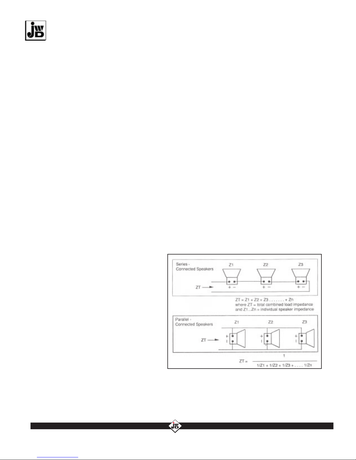
The speakers must be connected to present a
combined impedance equal to the selected ampli-
fier output impedance; i.e., 4, 8, 16 ohms. The
connections should be arranged in a series/parallel
combination to achieve this according to the
following formula. The impedance should be be-
tween 70% and 200% of the output impedance
selected. If the amplifier is to be driven anywhere
near its full rated output the impedance should be
well within these tolerances.
SERIES/PARALLEL COMBINATIONS
In larger systems it will be necessary to combine series and parallel connections to obtain the necessary
impedance. The rule for calculating the total effective impedance is to divide the entire circuit into indi-
vidual small series of parallel sub-circuits and apply the foregoing rules to them.
10

The transformer taps are marked in W=watts instead of Ohms (usually 4, 2, 1, ¹⁄₂). Again, it should be
born in mind that these levels of power output are only achieved when the transformer is working at 70.7
Volts. The transformers are connected in parallel. A good match is obtained by ensuring that the total of
all tap settings fits into the range of 40-80% of rated amplifier output. 80% is chosen to allow for trans-
former insertion loss. Also, It is good practice not to drive the amplifier to 100% of its capacity.
NEWTECHNOLOGY OLDRELIABILITY
J.W. Davis & Company 3030 Canton Street • P.O. Box 710219 • Dallas, Texas 75371-0219
Sales 800-527-5705 • Fax 800-388-9106 • Corp 214-651-7341 • Fax 214-939-0328 • [email protected] • www.jwd.com
•
The Mark of the Professional...
The following is an example using 16 8-Ohm speakers. Each
schematic is an impedance equivalent to its predecessor but
has been simplified.
(1) Reduced line losses and ability to use smaller wire gauges. This is due to the higher voltage
and reduced current in the speaker lines.
(2) Much simpler impedance matching procedures and connections.
Examples are shown below. For simplicity, it is assumed that all tap settings are the same at each
speaker. For a 120-Watt amplifier, the range 40-80% is equivalent to 48-96 Watts. Therefore:
A problem arises if one more speaker must be added at some
future date, as all the connections must be changed. This is
not a significant problem if only a few speakers are involved.
But if the network is extensive, the problem will be magnified.
Futhermore, failure of one speaker can take out a number of
associated units.
HIGH IMPEDANCE OF CONSTANT VOLTAGE (25 AND 70v)
SYSTEMS
The high impedance or constant voltage method of impedance
matching uses a high impedance amplifier output which is
transformed down to 8 Ohms by an impedance matching
transformer at each individual speaker. The big advantages of
this approach as compared to low impedance are:
Constant voltage is a misnomer in that the amplifier does not always produce 70V. Rather, the amplifier
output impedance is set at such a level that, irrespective of its rated power, it will produce70.7 Volts
output at full power. Thus a 10 Watt amplifier optimum load would have an impedance of 500 Ohms
(P = 70.7²/500), a 40-Watt amp would be 126 Ohms and 120-Watt amp, 42 Ohms.
Multiple transformer taps allow the impedance at each speaker to be adjusted individually to give a total
matched load. Because of the high impedance arrangement, the system is easier to impedance match
and is also inherently less susceptible to problems caused by mismatching.
11
18 speakers x 4 Watt taps each = 72W . . . . . . . . . . . Good match
12 speakers x 1 Watt taps each = 12W . . . . . . . . . . . Poor match
60 speakers x 1 Watt taps each = 60W . . . . . . . . . . . Good match
60 speakers x 4 Watt taps each = 240W . . . . . . . . . . Very poor match - overload
90 speakers x 1 Watt taps each = 90W . . . . . . . . . . . Good match
NOTE: None of the above tap settings guarantee the actual sound levels through each speaker.
This is a function of the master volume control as well as the tap setting. The tap setting simply defines
the maximum power consumed by an 8-Ohm speaker if presented with 70.7 Volt input. In systems with
a small number of speakers, it is always preferable to use a high tap setting and reduce the sound level by
turning down the master volume control. In calculating the amplifier rating needed for a typical music/
paging system using speakers distributed to an office environment, a good rule of thumb is to allow about
one watt per speaker and space speakers at 1¹⁄₂ x ceiling height. For noisy areas, or where the volume level
required is higher, more power is required.

NEWTECHNOLOGY OLDRELIABILITY
J.W. Davis & Company 3030 Canton Street • P.O. Box 710219 • Dallas, Texas 75371-0219
Sales 800-527-5705 • Fax 800-388-9106 • Corp 214-651-7341 • Fax 214-939-0328 • [email protected] • www.jwd.com
•
The Mark of the Professional...
VIII - POLARITY
All JWD speakers have the “hot” terminal marked with a “+” or a red dot. The “common” terminal is either unmarked or
marked with a “-”. Positive voltage applied to the “+” terminal will result in a forward or outward movement of the speaker
cone.
1. Connect one side of a 9-Volt battery to one speaker terminal.
2. Momentarily connect the other side fo the battery to the other speaker terminal.
3. Note the direction of the cone movement (inward or outward). If the cone movement is inward
(backward), reverse the battery leads.
4. Mark the speaker terminal connected to the positive side fo the battery as positive “+”.
5. Repeat the procedure for each successive speaker to ensure that the cone movement is
forward (outward) in each case.
XIX - POWER LOSS IN LONG LINES
For long lines, the power loss in watts becomes a significant factor. The power supplied by the amplifier is effectively
reduced by the line loss. For a 0.5 dB loss in sound pressure the total wire resistance must be limited to 6% of speaker
impedance. The table below shows the calculated two-wire cable lengths permissible for a number of wire sizes in feet.
For a 1 dB loss, the lengths may be doubled. For 2 dB loss, multiply by 4.4.
12
When using multiple speakers in a sound system installation, one must observe proper polarity of the speakers in order to
prevent the cancellation effects caused by adjacent speakers being in reverse polarity. Speakers in reverse polarity will
lose much of their normal volume and produce poor tonal quality.
For speakers facing in the same general direction, all speaker cones should move in unison in the same direction. When
two speakers face each other, the cone of one speaker should more inward when the other speaker cone moves outward.
If using speakers which are unmarked, or using speakers from various manufacturers, the following procedure will provide
a fast and simple test for polarity.

The Mark of the Professional...
NEWTECHNOLOGY OLDRELIABILITY
J.W. Davis & Company 3030 Canton Street • P.O. Box 710219 • Dallas, Texas 75371-0219
Sales 800-527-5705 • Fax 800-388-9106 • Corp 214-651-7341 • Fax 214-939-0328 • [email protected] • www.jwd.com
•
13
X - SCHEMATIC FOR INPUT MODULES 1-4

NEWTECHNOLOGY OLDRELIABILITY
J.W. Davis & Company 3030 Canton Street • P.O. Box 710219 • Dallas, Texas 75371-0219
Sales 800-527-5705 • Fax 800-388-9106 • Corp 214-651-7341 • Fax 214-939-0328 • [email protected] • www.jwd.com
•
The Mark of the Professional...
14
XI - SCHEMATIC FOR INPUT MODULES 5-6

NEWTECHNOLOGY OLDRELIABILITY
J.W. Davis & Company 3030 Canton Street • P.O. Box 710219 • Dallas, Texas 75371-0219
Sales 800-527-5705 • Fax 800-388-9106 • Corp 214-651-7341 • Fax 214-939-0328 • [email protected] • www.jwd.com
•
The Mark of the Professional...
15
XII - SCHEMATIC FOR CHASSIS BOARD

DA-120M Master Series Amplifier
Please Note:
Thank you for selecting a J. W. Davis DA-120M Amplifier. Since 1933 it has been our goal to
produce a complete line of quality products and to offer a FIVE YEAR WARRANTY on most J.
W. Davis items. We also promise that you or your customer will not see our products listed in a
discount catalog. You may sell J. W. Davis & Company products with confidence and pride.
For your next installation please consider the other fine J. W. Davis products such as power
amplifiers, pre-Amplifiers, mixers, microphones, speakers, speaker systems, horns, lecterns,
baffles, transformers, volume controls, and accessories.
Also, be sure to check our web site (www.jwd.com) for additional manufacturers’ products that we
distribute.
PURCHASE INFORMATION FOR YOUR RECORDS:
DA-120M SERIAL #
PURCHASE DATE
INSTALLATION DATE
PURCHASED FROM
ADDRESS
CITY & STATE
TELEPHONE #
NAME
NEWTECHNOLOGY OLDRELIABILITY
J.W. Davis & Company 3030 Canton Street • P.O. Box 710219 • Dallas, Texas 75371-0219
Sales 800-527-5705 • Fax 800-388-9106 • Corp 214-651-7341 • Fax 214-939-0328 • [email protected] • www.jwd.com
•
The Mark of the Professional...
Table of contents
Other J. W. Davis & Company Amplifier manuals