J. W. Davis & Company D-500A User manual

NEWTECHNOLOGY OLDRELIABILITY
J.W. Davis & Company •
3030 Canton Street • P.O. Box 710219 • Dallas, Texas 75371-0219
Sales 800-527-5705 • Fax 800-388-9106 • Corp 214-651-7341 • Fax 214-939-0328 • [email protected] • www.jwd.com
D-500A POWER AMPLIFIER
USER’S MANUAL
The Mark of the Professional...
090705124
Unpacking Procedures
The Back Panel
Specifications The Auto-Mute Circuit
Troubleshooting
The Front Panel
Maintenance
Installation Information
Speaker Installation
Using Horn Speakers
Product Overview
Schematic
Product Description
Warranty & Service
Accessories
2
2
3
3
3
4
4
5
. . . . . . . . . . . . . .
. . . . . . . . . . . . . . . . . . .
. . . . . . . . . . . .
. . . . . . . . . . . . . . . .
. . . . . . . . . . . .
. . . . . . . . . . . . . . . . . .
. . . . . . . . . . . . . . . . . .
. . . . . . . . . . . . . .
5
6
6
6
7
7
8
. . . . . . . . . . . . . . . .
. . . . . . . . . . . . . . .
. . . . . . . . . . . . . . . . . . . . . . . .
. . . . . . . . . . . . . . . . . .
. . . . . . . . . . . . . . . . . . . .
. . . . . . . . . . . . . . . . . . . . . . . .
. . . . . . . . . . . . . . . . . . . . . . . . . .

NEWTECHNOLOGY OLDRELIABILITY
J.W. Davis & Company •
3030 Canton Street • P.O. Box 710219 • Dallas, Texas 75371-0219
Sales 800-527-5705 • Fax 800-388-9106 • Corp 214-651-7341 • Fax 214-939-0328 • [email protected] • www.jwd.com
The Mark of the Professional...
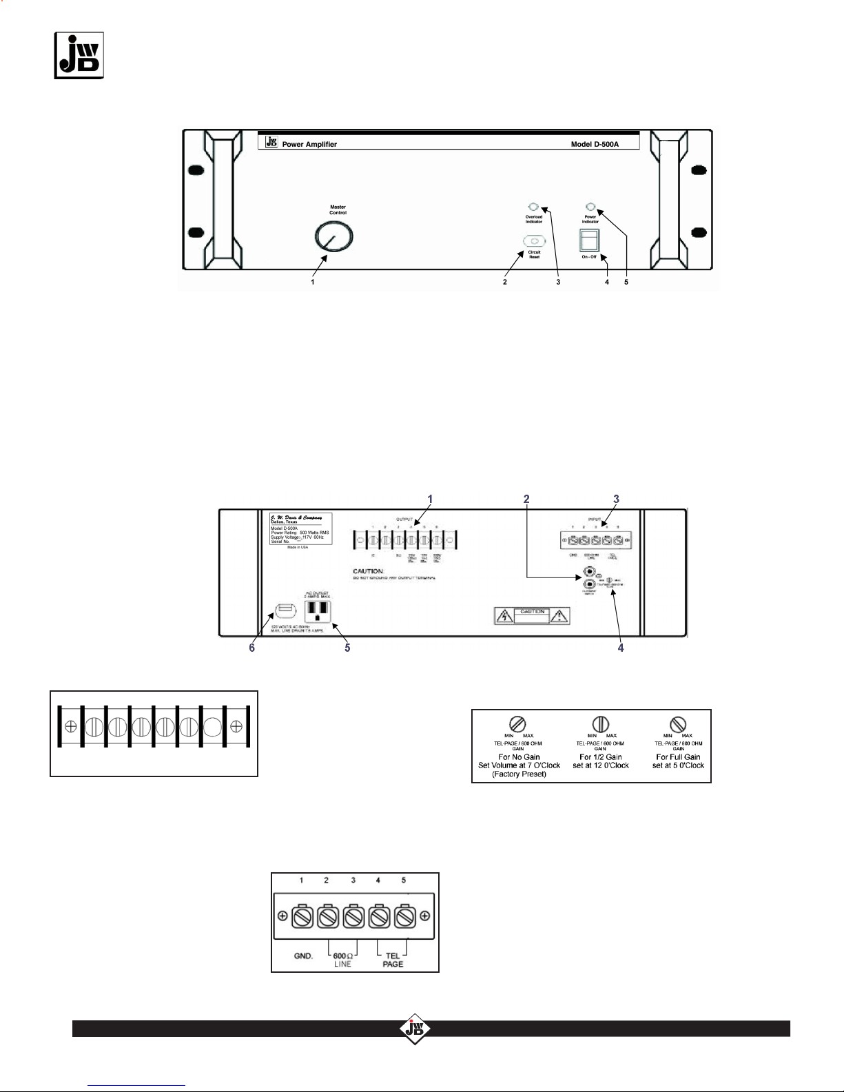
The D-500A is a 2-channel high fidelity commercial mono audio amplifier capable of delivering 500
watts of continuous RMS power into a direct coupled 8-ohm voice coil load or into a constant voltage
25V or 70.7V line. Only 3 racks in height, the D-500A uses a toroidal power transformer to reduce
weight, height, and noise. The D-500A, designed for commercial sound or “all-in-one” telephone paging
applications, offers a balanced 600-ohm/Tel-Page input that is capable of muting the two high Imped-
ance inputs that are strapped in parallel (Thereby offering a convenient auxiliary input bridge to addi-
tional amplifiers). The 600-ohm/Tel-Page level is controlled via an independent tamper-resistant control.
-2-
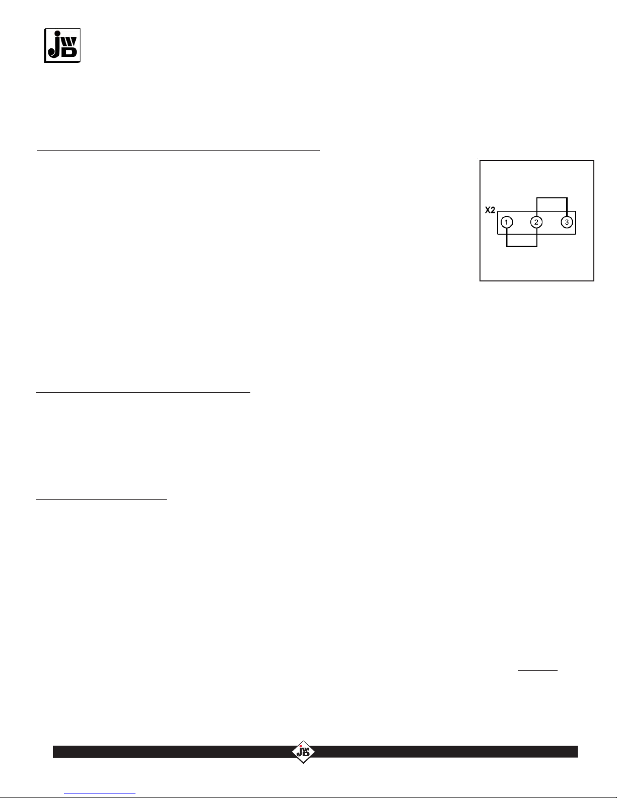
CAUTION: In the event the transformer’s
thermal breaker does nto reset, have the
trouble investigated by an authorized service
technician or return unit to the factory.
WARNING: TO REDUCE THE RISK OF FIRE
OR ELECTRIC SHOCK, DO NOT EXPOSE
THIS UNIT TO RAIN OR MOISTURE
CAUTION: These deviced are not intended for
use in hazardous locations as defined by the
National Electrical Vode (NEC) and by the
National Fire Protection Association (NFPA).
WARNINGS
Features
Rack mount standard 3 RU
•Automatic voice activated Hi-Z muting
Multiple protections including relay, short
circuit and A/C circuit breaker
Rugged power supply designed for
continuous use
Convection cooled—reliable “no maintenance”
design
•
•
•
•
WARNING: THIS AMPLIFIER MUST BE
GROUNDED. DO NOT REMOVE GROUND PIN
FROM AC PLUG OR USE A DEVICE TO CHANGE
FROM A 3-PIN AC PLUG.
•Fully isolated output transformer for 25 and
70.7 volt line operation
•Auxiliary RCA type Inputs for receiving source
signal and bridging source signal out
•Independent input gain control for 600 ohm
telephone paging
•500 watts continuous RMS power
•4Ω, 8Ω, 25V or 70.7V outputs
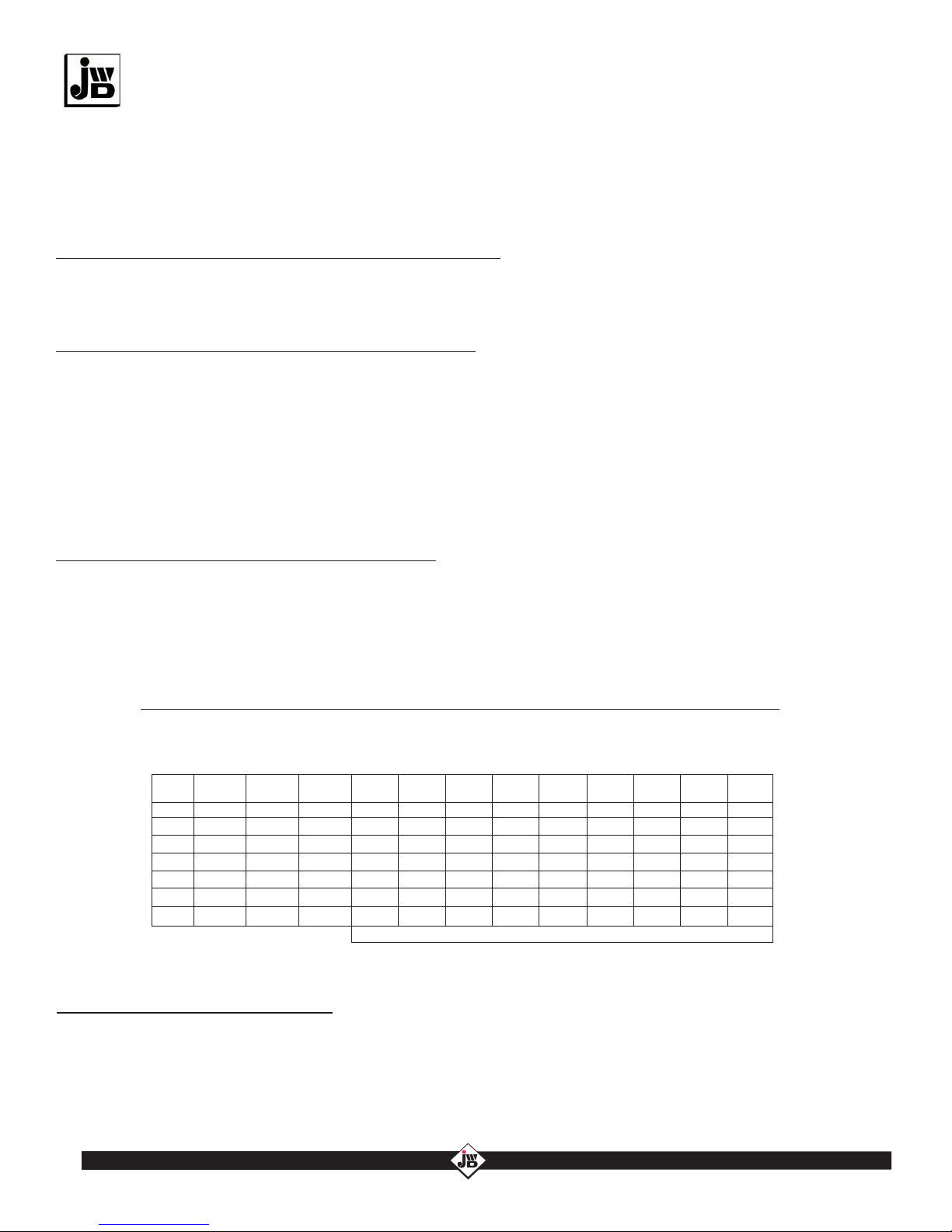
Inputs
Distortion at Rated Output
Power Output
Audio Output
Frequency Response
Power Source
Hum/Noise
Dimensions
Auxiliary, 2 RCA Connectors in Parallel for Input and Bridging. High Impdeance
Unbalanced, 0.50V, 10k Ohm.
Telephone Page, Screw Terminal, 50mV, 600 Ohm Balanced, with VOX Mute.
Line Level, 600 Ohm Balanced Input, 0.50V
500 Watts RMS Rated at 4, or 8 Ohm Direct, 25V, or 70.7V
4, or 8 Ohm, 25V, or 70.7V
</= 0.3% THD
±3dB 20 to 20kHz (Direct Output); ±2dB 50Hz-15kHz on 25V, or 70.7V output
90dB Below Rated Output
120VAC 60Hz
5.25" (H) x 19" (W) x 13.5" (D)
SPECIFICATIONS
Weight
Finish
43 lbs.
Flat Black

NEWTECHNOLOGY OLDRELIABILITY
J.W. Davis & Company •
3030 Canton Street • P.O. Box 710219 • Dallas, Texas 75371-0219
Sales 800-527-5705 • Fax 800-388-9106 • Corp 214-651-7341 • Fax 214-939-0328 • [email protected] • www.jwd.com
The Mark of the Professional...
I. UNPACKING PROCEDURES
INSPECTION
This unit was carefully checked and packed before leaving the factory. However, each shipment should be
inspected by observing the shipping container and unit for indications of improper handling. If damage has
been found, an immediate claim should be made to the shipping company. Keep all cartons and packing
material for inspection. Do not call J. W. Davis & Company or return the shipment to J. W. Davis &
Company until the shipment has been examined by the shipping company. Failure to permit the shipping
company to examine the shipment at the arrival point may void subsequent settlement. If there is a problem after
the shipping company has made its inspection, then call Customer Service at J. W. Davis & Company for
assistance.
INITIAL PERFORMANCE CHECK
Complete the inspection with an initial performance check. Connect a test speaker to the 8-ohm direct output
terminals. Then connect a tuner, tape deck, or CD player to the auxiliary input and set the controls for operation.
If the unit should be inoperable and no damage is noted, please contact J. W. Davis & Company’s Customer
Service Department for directions (800-527-5705).
III. INSTALLATION INFORMATION
RACK MOUNTING
For best results use a 10-32 class UNF-2B or 12-24 class UNC-2B rack and 0.625 inch machine screws (metric:
M5X8-6H or M6X1-6H, 15.88mm). It is recommended that the drive of these screws be phillips to protect the
finish from unnecessary scratches. Nylon or plastic washers are recommended which will not only help protect
the finish but also aid in retaining the screws.
CONVECTION, FAN COOLING, AND VENTILATION
This unit is cooled via convection and therefore designed for continuous operation. Do not block the unit’s
heatsink fins or the vent holes located in the cover. If the unit will be rack mounted, a cooling fan must be used
that is capable of exhausting not less than 300CFM. The fan must be mounted to the inside top of the rack,
above the amplifier.
II. PRODUCT OVERVIEW
-3-
Outputs:
4-8 ohm/25V/70.7
Tel-Page
Microphone
Input
Patch Feature
For Additional Amplifier
Two Aux Inputs
Strapped
in Parallel
Music Input
Source
Inputs
Auto-Mute
Amplification:
600W
D-500A POWER AMPLIFIER
CAUTION: TO PROTECT THE SPEAKER FROM DAMAGE, DO NOT TURN
THE UNIT ON UNTIL ALL CONNECTIONS HAVE BEEN MADE. IN ADDITION,
BE SURE THAT THE UNIT IS GROUNDED BEFORE TESTING.

NEWTECHNOLOGY OLDRELIABILITY
J.W. Davis & Company •
3030 Canton Street • P.O. Box 710219 • Dallas, Texas 75371-0219
Sales 800-527-5705 • Fax 800-388-9106 • Corp 214-651-7341 • Fax 214-939-0328 • [email protected] • www.jwd.com
The Mark of the Professional...
IV. THE FRONT PANEL
V. THE BACK PANEL
1 - VOLUME CONTROL Adjusts the master volume level of
output for the amplifier.
2 - CIRCUIT BREAKER Pushing this plunger resets the
circuit breaker should the breaker trip. The circuit may
need to be resetfor two reason: 1) The amplifier is
continuously being overloaded, 2) The internal temperature
surpasses the safe operating range. NOTE: Before
resetting the circuit, be sure to first correct the problem
causing the overload or overheating.
4 - POWER SWITCH This switch turns the unit on or off.
5 - POWER INDICATOR This green LED will light when
the power is switched on.
3 - OVERLOAD INDICATOR This red LED will light/flash
at full power and on peaks. A steady bright glow could
indicate a shorted speaker line, too much load, or oscillation
in the system.
6 - AC LINE CORD Three conductor line cord for AC
supply voltage.
5 - AC CONVENIENCE OUTLET Grounded outlet to
run additional equipment (2 amp maximum).
2 - INPUT/PATCH These are two high impedance inputs connect-
ed in parallel. One is for signal input, the other for bridging to a
second amplifier that will allow increasing the power to the entire
system.
3 - INPUT TERMINAL SCREW STRIP This strip is designed
to accept either a 600 ohm bal-
anced input or a Tel-Page balanced
input. These inputs, differing only in
sensitivity, are designed for wide
acceptance without the need for
any accessories. It is recommend-
ed to use ground reference on the
input whenever and wherever possible.
1 - OUTPUT TERMINAL SCREW STRIP Four outputs are
provided on this strip; the voice
coil output for 4 ohm and 8
ohm speaker loads, and the
25V and 70.7V speaker line
outputs.
-4-
4 - 600 OHM/TEL-PAGE INPUT GAIN CONTROL This
recessed control adjusts the level of the 600 ohm Tel-
Page input
without effect-
ing the level of
the high imped-
ance input. It is
factory preset at 0. This input will mute the Hi-Z inputs
automatically. To defeat this feature see “Part VIII. The
Auto-Mute Circuit” on page 6.
4Ω8ΩC 25V
1.25Ω
Min
70V
10Ω
Min
12 3 4 56

The Mark of the Professional...
The D-500A is designed to be connected to 4 ohm or 8 ohm speakers directly, or to variable impedance speakers
that match the amplifier’s line output voltage of 25V or 70.7V speaker lines.
VI. SPEAKER INSTALLATION
CONNECTING FOR DIRECT 4, or 8 OHM OPERATION
Connect 4-ohm speaker(s) to terminals 1 (-) and 2 (+), or 8-ohm speaker(s) to 1 (-) and 3 (+). For proper signal
phasing, observe +/- polarity. NOTE: This is a bridged output. Do not ground either of these terminals.
For 25V output, connect the load to terminals 1 (-) and 4 (+). For 70.7V output, connect the load to terminals 1 (-)
and 5 (+).
CONNECTING FOR 25V or 70.7V LINE OPERATION
Cable distance should be kept as short as possible to minimize power loss. The chart below can be used as a
general guide showing various wire sizes and the maximum distance related to cable loading that speakers can
be placed from the unit for an approximate -0.5dB loss (-12.5% power). To allow for future expansion and
distributed cable line loss, it is recommended the total system wattage should not exceed 80% of the amplifier’s
rated output. To determine the total system wattage, sum the wattage tap of all speaker(s)/horn(s) used.
USING THE PROPER WIRE SIZE AND LENGTH
70.7V SPEAKER LINE
(FOR 25V LINE DIVIDE ALL 70.7V LENGTHS BY 8)
NOMINAL POWER IN LOAD
LOW IMPEDANCE
SPEAKER LINE
AWG
SIZE
2 WIRE COPPER CABLE LENGTHS FOR SPEAKER LINES AT -0.5dB LOSS IN SPL (12.5% POWER LOSS IN WATTS)
VII. USING HORN SPEAKERS
ENABLING THE LOW CUT FILTER
If horn speakers are being used, the low cut filter must be activated to protect them. To enable the low cut circuit,
follow these steps. 1) On the same board as the VOX-Mute, look for a tagged jumper that reads, “To activate low
cut filter, cut this jumper.” 2) Cut the jumper and make sure the jumper halves do not touch any of the other part
of the board. The low-cut filter begins to roll off frequencies at 120Hz. NOTE: For complete protection of
compression drivers, or horn diaphrams additional electronic equipment may be necessary.
NOTE: When using the amp’s 25V or 70.7V line operation, the proper tap setting of the impedance matching
transformer determines the individual speaker’s power level. Using these transformers allows the speakers to be
placed at longer distances from the amplifier without significant power loss. The number of speakers for a line-
driven central amplifier system is limited to the power available from the amplifier. The sum of all connected
speakers’ power settings must not exceed 80% of the total power available from the amplifier.
NEWTECHNOLOGY OLDRELIABILITY
J.W. Davis & Company •
3030 Canton Street • P.O. Box 710219 • Dallas, Texas 75371-0219
Sales 800-527-5705 • Fax 800-388-9106 • Corp 214-651-7341 • Fax 214-939-0328 • [email protected] • www.jwd.com
-5-
4 OHMS 8 OHMS 16
120 240 480
75 150 300
50 95 190
30 60 120
20 40 75
15 25 50
10 15 30
7.5W 15W 30W
- - 5,000
- 6,200 3,100
7,600 3,800 1,900
4,800 2,400 1,200
1,500
1,920 960 480
1,200 600 300
60W 100W 125W
2,500 1,500 1,100
1,550 940 750
950 600 450
600 370 290
375 230 180
240 150 110
150 95 -
250W 400W 500W
550 365 275
375 230 185
225 140 110
145 90 -
90 - -
---
---
10
12
14
16
18
20
22
WIRE LENGTHS IN FEET
3,000 750

NEWTECHNOLOGY OLDRELIABILITY
J.W. Davis & Company •
3030 Canton Street • P.O. Box 710219 • Dallas, Texas 75371-0219
Sales 800-527-5705 • Fax 800-388-9106 • Corp 214-651-7341 • Fax 214-939-0328 • [email protected] • www.jwd.com
The Mark of the Professional...
VIII. THE AUTO-MUTE CIRCUIT
The JWD series of mixer amplifiers include a built-in automatic mute circuit. The MIC/
TEL-PAGE/600 ohm input channel, can automatically mute the AUX channel. This unit is
factory installed to auto-mute, however, the mute is defeatable by moving the internal
mute jumper to its other position.
To defeat the auto-mute circuit follow these steps. 1) Unplug the A/C cord. 2) Remove
the hood and find the input board located on the back panel. 3) On the board locate the
header X2 (See the figure to the right). Change the shunt position from positions 1 and 2
to 2 and 3 and the auto-mute will be defeated.
DISABLING OR ENABLING THE AUTO-MUTE CIRCUIT
If a the unit is overloaded or it overheats, the AC line circuit breaker on the front panel will open. Before
resetting the circuit, determine and correct the problem causing the overload of overheating (see
“Troubleshooting” on page 7 for a chart to help guide you in determining the cause of the problem). If after
exhausting the possibilities, the circuit breaker will not reset, have the unit serviced by a qualified technician.
NOTE: If the unit is rack mounted, you must utilize a cooling fan that is capable of exhausting not less than
300CFM.
The D-500A is built to last and therefore comes equipped with multiple built-in protections including relay, short
circuit, and AC circuit breaker. If the unit is overloaded (e.g. too many speakers, shorted speaker line,
mismatched line impedance [e.g. 8 ohm speaker on 70.7V line]) or overheated (e.g. obstructed or poor
ventilation of the unit, mismatched line impedance) the unit will fail to provide output. Overloading and
overheating of the amp can lead to premature output failure.
RESETTING THE AC CIRCUIT BREAKER
REPLACING THE FUSES
Additional protection is provided by fuses in the power supply which protect the transformer. If an output is
shorted the fuses will blow. Before replacing the fuses, determine and correct the problem causing the fuses to
blow (see “Part X. Troubleshooting” on page 8 for a chart to help guide you in determining the cause of the
problem). To safely replace the fuses: 1) Disconnect the AC power cord; 2) Remove the top cover screws and
cover; 3) Replace blown fuses with same type and size; 4) Reinstall the top cover securely; 5) Reconnect the
AC power cord.
IX. MAINTENANCE
Connect shunt here to
disable the Auto-Mute
Connect shunt here to
enable the Auto-Mute
(Fa cto ry-Pres et)
The Auto-Mute Circuit
X. WARRANTY & TECHNICAL SUPPORT
For a period of five (5) years from the date of original purchase, J. W. Davis & Company warrants that it will
correct any defects in material or workmanship in the D-500A without charge. However, this warranty does not
apply to equipment which in the opinion of J. W. Davis & Company has been subjected to abuse or accident,
improper installation or alteration in any way. If the D-500A fails to operate during this period, return prepaid to
J. W. Davis & Company Warranty Service with a letter explaining the problem and proof of purchase.
Should you require further technical support, please contact our Customer Service Department for assistance
through any of the channels shown below.
-6-

NEWTECHNOLOGY OLDRELIABILITY
J.W. Davis & Company •
3030 Canton Street • P.O. Box 710219 • Dallas, Texas 75371-0219
Sales 800-527-5705 • Fax 800-388-9106 • Corp 214-651-7341 • Fax 214-939-0328 • [email protected] • www.jwd.com
Power Indicator on
Front Panel Does
Not Glow:
Overload Indicator
on Front Panel
Glows Steadily:
No Audio
Output:
No Automatic
Muting of Input
Signal:
No AC power present
Unit’s AC circuit breaker is
tripped
• Verify the unit is receiving AC power.
• Verify the AC circuit breaker is not tripped. If so, depress the
plunger to reset.
• Verify the unit’s internal fuse(s) has not tripped. If it has,
replace the tripped fuse with the same type and value fuse
Input or output impedance not
matched
Signal in level too high
•Check that the proper input/output line impedance matches
the selected input/output connections used.
• Lower the signal in level.
No input signal source
Incorrect input signal connection
Incorrect output connections
600 ohm/Tel-Page gain control
on back panel too low
• Verify that proper signal/level is being supplied.
•Verify that the signal input connection is correctly connected.
•Check that the ouput connection has been properly made.
• Check 600 ohm/Tel-Page gain control setting (recessed on
back).
Internal jumper setting
Insufficient 600 ohm/Tel-Page
gain
• Check that the internal muite jumper is not disabled. (See
page 7.)
• Check 600 ohm/Tel-Page gain control setting (recessed on
back).
Low, High, or
Distorted Level:
Volume setting
Signal input level is too low
Signal input level is too high
Input or output impedance not
matched
• Check the corresponding gain control on the front panel or
the 600ohm/Tel-Page control (recessed on the back).
• Check that adequate input signal level is strong enough.
•Reduce input signal accordingly.
• Check that the proper input/output line impedance matches
the selected input/output connections used.
Possible low resistance or
shorted wiring across the audio in
and/or across the speaker out
• Check/correct system wiring.
SYMPTON POSSIBLE CAUSE POSSIBLE SOLUTIONS(S)
The Mark of the Professional...
XI. TROUBLESHOOTING
• Verify the AC outlet has proper AC voltage available
XII. OPTIONAL ACCESSORIES
Optional 600-ohm Isolation Transformer (IT-600)
Speaker Lightening Suppressor (SLS)
Tel-Page Line-lightning Suppressor (TLS)
Universal ADD-ON-AMP (AO-1A) used to match 4 or 8-ohm, 25V and 70V speaker line to MIC or
Auxiliary input of amplifier
-7-
Signal Matching Attenuator, Matches Signal from Tuner or Other high Z Device to Amplifier MIC Input
Signal Matching Attenuator, Matches Signal from Telephone Line or Other Low Z Device to Amplifier MIC Input
Signal Matching Attenuator, Matches Signal from 70V Speaker Line Output to AUX Input of Second Amplifier
•
•
•
•
•
•
•

SCHEMATIC FOR D-500A AMPLIFIER
Table of contents
Other J. W. Davis & Company Amplifier manuals