Jafar 8851 Manual

OPERATION AND MAINTENANCE MANUAL 01-2016
Operation
& Maintenance Manual
UNDERGROUND FIRE HYDRANT
P/N
TYPE 885
TYPE 8852
Approved for use by
President of Factory, JAFAR S.A.
Failure to comply with the guidelines and instructions in this Operation and
Maintenance Manual releases the manufacturer from all obligations, liability and guarantee.
Due to continuous business development, we reserve the right to introduce
modifications and structural changes to the presented product.

OPERATION AND MAINTENANCE MANUAL 01-2016
2
TABLE OF CONTENTS
1 TECHNICAL DESCRIPTION............................................................................................................................ 3
1.1 PRODUCT NAME AND FEATURES......................................................................................................... 3
1.2 PURPOSE..................................................................................................................................................... 3
1.3 TECHNICAL SPECIFICATION.................................................................................................................. 3
2 STRUCTURE...................................................................................................................................................... 3
2.1 HYDRANT DESIGN DESCRIPTION......................................................................................................... 3
2.2 MATERIALS TYPE 8851.......................................................................................................................... 10
2.3 DIMENSIONS TYPE 8851........................................................................................................................ 11
2.4 MATERIALS TYPE 8852.......................................................................................................................... 12
2.5 DIMENSIONS TYPE 8852........................................................................................................................ 13
2.6 STANDARDS............................................................................................................................................. 14
2.7 ORDERING REGULATIONS ................................................................................................................... 15
2.8 MANUFACTURE AND ACCEPTANCE.................................................................................................. 15
2.9 MARKINGS ............................................................................................................................................... 15
3 PROTECTION, STORAGE & TRANSPORT.................................................................................................. 15
3.1 PROTECTIVE COATINGS....................................................................................................................... 15
3.2 PACKAGING............................................................................................................................................. 15
3.3 STORAGE.................................................................................................................................................. 16
3.4 TRANSPORT ............................................................................................................................................. 16
4 ASSEMBLY AND INSTALLATION............................................................................................................... 16
4.1 INSTALLATION GUIDELINES............................................................................................................... 16
4.2 INSTALLATION INSTRUCTIONS.......................................................................................................... 17
4.3 OPERATION.............................................................................................................................................. 19
4.4 OH&S REGULATIONS............................................................................................................................. 20
5 GUARANTEE CONDITIONS.......................................................................................................................... 20

OPERATION AND MAINTENANCE MANUAL 01-2016
3
1 TECHNICAL DESCRIPTION
1.1 PRODUCT NAME AND FEATURES
The subject of this O&MM is:
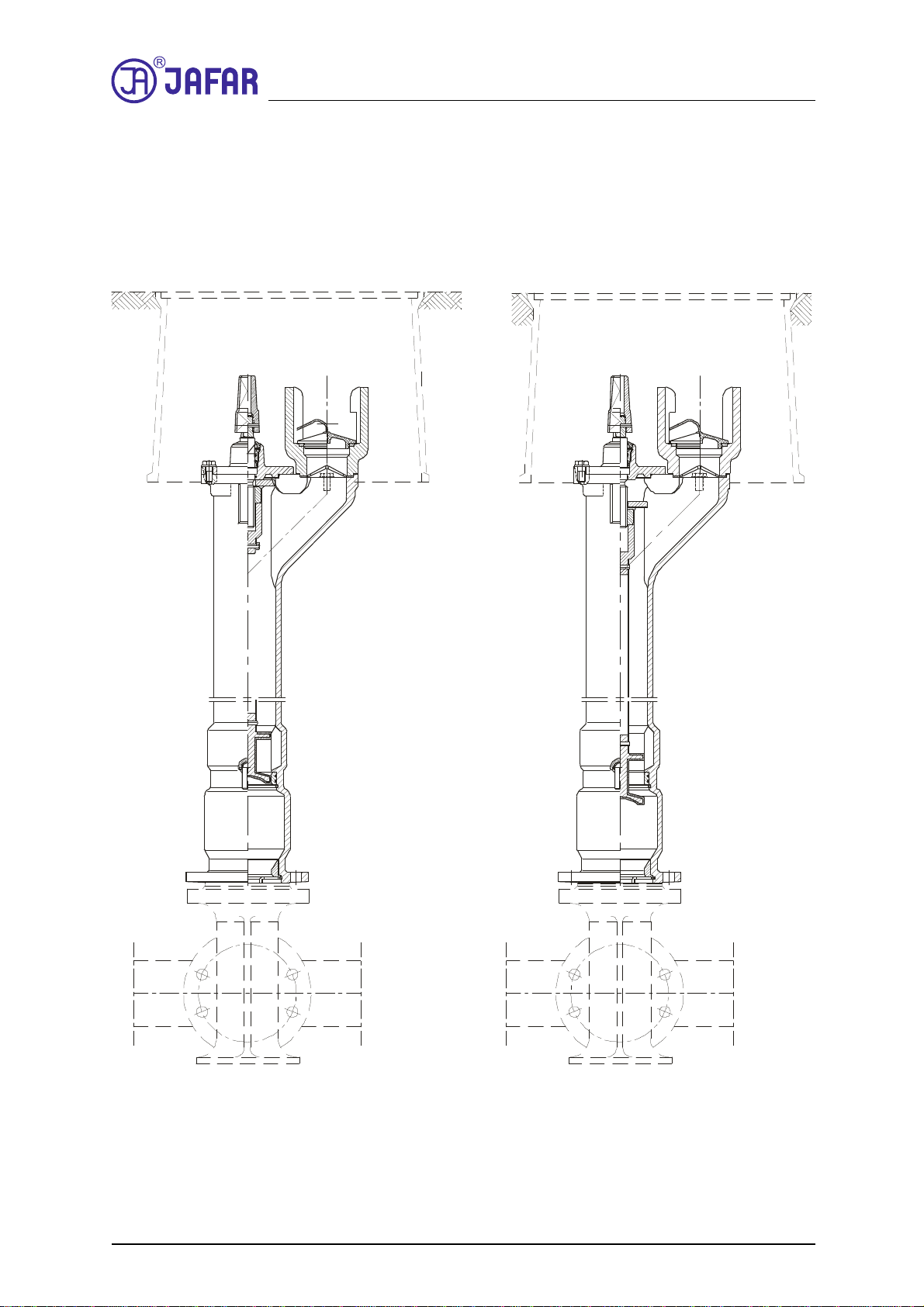
Underground full flow hydrant with single closure TYPE 8851
- With additional protection against flow in the form of ball valve;
located below poppet TYPE 8852
- With automatic water drainage activated by medium flow stoppage;
- With poppet (closure) embedded in 100% pure elastomer;
- Internal parts may be replaced without cutting off flow (TYPE 8852).
1.2 PURPOSE
Underground fire hydrants with single closure and additional flow protection are intended for fire
protection systems, for chemically neutral pure water, free of solid impurities and for industrial systems. For
use on underground installations on pipelines laid horizontally below the freezing zone.
1.3 TECHNICAL SPECIFICATION
Underground fire hydrants with single closure and additional flow protection are intended for transport
of potable water and industrial water at temperatures from +1°C to +50°C.
- Available diameters (dimensions) DN80 -DN 100[mm]
- Maximum medium flow rate: - liquid up to 4 [m/s]
- driving torque at opening start and closing end are listed below:
DN [mm]
80 100
Mmax [Nm]
80 80
- equipment control: closing direction in the standard version of hydrant:
clockwise closing sense of rotation.
The closing sense of rotation can be opposite on special order.
-connection flanges are manufactured in accordance with PN-EN 1092-2:1999
with the dimensions adequate to the relevant nominal pressure of 1.6 MPa.
-Hydrant's efficiency with nominal pressure 0.2 MPa is:
10 dm
3
/s – above ground DN80
15 dm
3
/s – above ground DN100
In accordance with PN-B-02863: 1997 "Fire water supply"
-Key for controlling valves and taps PN-63/M-74085
-Manufactured in accordance with PN-EN 14339:2009
2 STRUCTURE
2.1 HYDRANT DESIGN DESCRIPTION
The underground hydrant is a column with internal structure to enable drawing water from main
pipeline. In the lower part of the hydrant there is a cast-iron valve chamber with a poppet acting as closing
element and a drainage device. The chamber housing is connected to the ball's (ball return valve) valve chamber
finished with a connection flange for installing the hydrant on the pipeline. The top body also has a driving
element on the end of bolt used for transferring rotational movement to the hydrant's poppet via distance pipe.
The hydrant's main body has a toothed socket for connecting a hydrant stand which is used for attaching fire
hoses.
The rotating stem is seated in a stopper with rubber sealing rings. Rotate the hydrant clockwise to close the
flow. Poppet moves during rotation of the stem and flow opens. The poppet's movement closes the water draining

OPERATION AND MAINTENANCE MANUAL 01-2016
4
device's outlet opening. When closing a hydrant, the poppet lands in the seat and the water remaining in the
hydrant's column is drained using the draining hole.
With hydrant TYPE 8852, it is possible to replace the complete internal equipment of a hydrant without cutting
off the supply thanks to a ball valve.

OPERATION AND MAINTENANCE MANUAL 01-2016
5
Operation diagram for hydrant TYPE 8851 DN80
8851.1
CLOSE OPEN
-{}-

OPERATION AND MAINTENANCE MANUAL 01-2016
6
Operation diagram for hydrant TYPE 8851 DN80
8851.2
CLOSE OPEN

OPERATION AND MAINTENANCE MANUAL 01-2016
7
Operation diagram for hydrant TYPE 8851 DN80
8851.3
CLOSE OPEN

OPERATION AND MAINTENANCE MANUAL 01-2016
8
Operation diagram for hydrant TYPE 8852 DN80
8852.1
CLOSE OPEN

OPERATION AND MAINTENANCE MANUAL 01-2016
9
Operation diagram for hydrant TYPE 8852 DN80
8852.2
CLOSE OPEN
The order of operations during opening and closing of a hydrant type 8852 configured with a shutoff gate
valve.
- Starting:
1. Open the shutoff gate valve.
2. Open the hydrant.
- Stopping:
3. Close the hydrant.

OPERATION AND MAINTENANCE MANUAL 01-2016
10
Caution! It is prohibited to open this type of hydrant with a closed shutoff gate valve because the poppet
sliding down must be able to push a water column in the direction opposite to the flow direction during the
first phase of its movement.
2.2 MATERIALS TYPE 8851
List of basic materials used for the construction of an underground hydrant TYPE 8851
see table
Item
Part name Material Reference standard
1Main body Cast-iron, EN-GJS 400-15
EN-GJS500-7 PN-EN1563: 2012
2 Ball chamber Cast-iron, EN-GJS 400-15
EN-GJS500-7 PN-EN1563: 2012
3Column
Cast-iron, EN-GJS 400-15
EN-GJS500-7
Steel 1.0254
Stainless steel 1.4301
PN-EN1563: 2012
PN-EN 1,503-3:2003
PN-EN 10088-1:2014
4 Cover Cast-iron, EN-GJS 400-15
EN-GJS500-7 PN-EN1563: 2012
5Poppet Cast-iron, EN-GJS 400-15
EN-GJS500-7
EPDM
PN-EN1563:2012
PN-ISO1629:2005
6Cap Cast-iron, EN-GJS 400-15
EN-GJS500-7 PN-EN1563: 2012
7Stem Stainless steel 1.4021 PN-EN 10088-1: 2014
8Spindle Stainless steel 1.4301 PN-EN 10088-1:2014
9Tooth socket Cast-iron, EN-GJS 400-15
EN-GJS500-7 PN-EN1563: 2012
10 Gasket EPDM PN-ISO 1629:2005
11 Outlet seal EPDM PN-ISO 1629:2005
12 Deflector EPDM PN-ISO 1629:2005
13 Stopper Brass PN-EN 1982:2010
14 Stem nut Brass PN-EN 1982:2010
15 O-ring EPDM PN-ISO 1629:2005
16 Bolt Steel St3S/Zn5
Stainless steel, A2 PN-EN ISO 4017: 2011
PN-EN ISO 4762: 2006
17 Nut Steel St3S/Zn5
Stainless steel, A4 PN-EN ISO 4032: 2013
18 Drainage Polypropylene PP PN-EN ISO 1873-1:2000
19 Seat Brass PN-EN 1982:2010

OPERATION AND MAINTENANCE MANUAL 01-2016
11
2.3 DIMENSIONS TYPE 8851

OPERATION AND MAINTENANCE MANUAL 01-2016
12
DN RD H H
1
8851.1 8851.2 8851.3
750 665 500 - 30
1000 915 750 - 34 -
1250 1165 1000 - 39 44
1500 1415 1250 - 45 52
1800 1715 1500 - - -
1000 935 750 50 - -
1250 1185 1000 56 - -
1500 1435 1250 62 - -
1800 1735 1500 70 - -
100
Weight
[kg]
[mm]
80
2.4 MATERIALS TYPE 8852
List of basic materials used for the construction of an underground hydrant TYPE 8852
see table
Item
Part name Material Reference standard
1Main body Cast-iron, EN-GJS 400-15
EN-GJS500-7 PN-EN1563: 2012
2 Lower body Cast-iron, EN-GJS 400-15
EN-GJS500-7 PN-EN1563: 2012
3 Nut holder Cast-iron, EN-GJS 400-15
EN-GJS500-7 PN-EN1563: 2012
4Cover Cast-iron, EN-GJS 400-15
EN-GJS500-7 PN-EN1563: 2012
5Poppet Cast-iron, EN-GJS 400-15
EN-GJS500-7
EPDM
PN-EN1563:2012
PN-ISO1629:2005
6Cap Cast-iron, EN-GJS 400-15
EN-GJS500-7 PN-EN1563: 2012
7Stem Stainless steel 1.4021 PN-EN 10088-1: 2014
8Spindle Stainless steel 1.4301 PN-EN 10088-1:2014
9Tooth socket Cast-iron, EN-GJS 400-15
EN-GJS500-7 PN-EN1563: 2012
10 Gasket EPDM PN-ISO 1629:2005
11 Outlet seal EPDM PN-ISO 1629:2005
12 Deflector EPDM PN-ISO 1629:2005
13 Stopper Brass PN-EN 1982:2010
14 Stem nut Brass PN-EN 1982:2010
15 O-ring EPDM PN-ISO 1629:2005
16 Bolt Steel St3S/Zn5
Stainless steel, A2 PN-EN ISO 4017: 2011
PN-EN ISO 4762: 2006
17 Nut Steel St3S/Zn5
Stainless steel, A4 PN-EN ISO 4032: 2013
18 Ball Cellular polypropylene or aluminium
alloy AlSi/EPDM PN-EN 1706:2011
PN-ISO 1629:2005

OPERATION AND MAINTENANCE MANUAL 01-2016
13
19 Seat Brass PN-EN 1982:2010
20 Drainage Polypropylene PP PN-EN ISO 1873-1:2000
2.5 DIMENSIONS TYPE 8852

OPERATION AND MAINTENANCE MANUAL 01-2016
14
DN RD H H
1
8852.1 8852.2
1000 915 750 36 -
1250 1165 1000 46 45
1500 1415 1250 54 53
1800 1715 1500 64 -
1000 935 750 55 -
1250 1185 1000 59 -
1500 1435 1250 63 -
1800 1735 1500 68 -
100
Weight
80
[mm]
2.6 STANDARDS
PN-EN 1074-1: 2002 Valves for water supply. Fitness for purpose requirements and appropriate
verification tests. General requirements
PN-EN 1074-6: 2009 Valves for water supply. Fitness for purpose requirements and appropriate
verification tests. Hydrants.
PN-89/H-02650 Fittings and pipelines. Pressures and temperatures.
PN-EN 19:2005 Industrial valves. Marking of metallic valves.
PN-EN 1092-2: 1999 Flanges and their connections. Circular flanges for pipes,
valves, fittings and accessories, PN designated. Cast iron flanges.
PN-EN ISO 6708: 1998 Pipework components. Definition and selection of DN (nominal size).
PN-EN 1559-1: 2011 Founding. Technical conditions of delivery. General.
PN-EN1563: 2012 Founding. Spheroidal graphite cast irons.
PN-EN1370: 2012 Founding. Examination of surface condition by
visual-tactile comparators.
PN-EN14339: 2009 Undergound hydrants.
PN-EN 10088-1: 2014 Stainless steels. List of stainless steels.
PN-89/H-84023/07 Specific application steel. Pipe steel. Grades.
PN-EN 1706 2011 Aluminium and aluminium alloys. Foundings. Chemical composition and
mechanical properties. .
PN-EN1982: 2010 Copper and copper alloys. Ingots and castings.
PN-EN12420: 2002 Copper and copper alloys. Forgings.
PN-ISO 965-1: 2001 ISO general purpose metric screw threads. Tolerances. Principles and basic
data.
PN-ISO 2903: 1996 Trapezoid ISO metric threads. Tolerances.
PN-EN ISO 4762:2006 Hexagon socket headcap screws.
PN-EN ISO 4017:2011 Hexagon head screws.
Product grades A and B.
PN-EN ISO 4014:2011 Hex head bolt. Product grades A and B.
PN-EN ISO 4032:2013 Hexagon regular nuts (style 1). Product grades A and B.
PN-EN ISO 7091:2003 Plain washers. Normal series. Product grade C
PN-77/M-82008 Spring washers.
PN-EN ISO 8752:2009 Spring-type straight pins. Slotted, heavy duty.
PN-69/M-80202 Steel wires 1x7.
BN-89/8511-15 Metallic seals.
PN-ISO 1629: 2005 Rubbers and lattices. Nomenclature.
PN-EN ISO 1873-1: 2000 Plastic materials. Polypropylene (PP) moulding and extrusion materials.
Designation system and basis for specifications.
PN-EN ISO 1872-1:2000 Plastic materials. Polyethylene (PE) moulding and extrusion materials.
Designation system and basis for specifications.

OPERATION AND MAINTENANCE MANUAL 01-2016
15
PN-EN ISO 12944-5: 2009 Paints and varnishes. Anti-corrosion protection of steel structures by means of
protective painting systems. Protective paint systems.
2.7 ORDERING REGULATIONS
Underground fire hydrants are specific purpose industrial valves, therefore orders must include:
- product's catalogue number,
- intended use, e.g. for fire water supply systems;
furthermore:
- nominal diameter — acc. to PN-EN ISO 6708: 1998
- nominal pressure, acc. to PN-89/H-02650;
- type of body material — acc. to PN-EN 1563: 2012
- max. operating temperature — acc. to PN-89/H — 02650.
2.8 MANUFACTURE AND ACCEPTANCE
The underground hydrants are accepted and produced in accordance with: PN-EN 1074-6:2005 (Valves for
water supply. Fitness for purpose requirements and appropriate verification tests. Hydrants.) and PN-EN
14339:2005
(Underground hydrants). All hydrants (100%) are subject to tightness testing. The tests include external body
tightness and closing tightness.
2.9 MARKINGS
The underground hydrants are marked in accordance with: PN-EN-19: 2005, PN-EN-1074-6: 2009
markings on the front and back walls of the body chamber. The marking contains the following data:
- nominal diameter
- nominal pressure
- type of body material
- manufacturer trade mark
- direction of medium flow.
The location on the valve specified in the documentation features the nameplate which contains the
following data: - manufacturer's company name and logo
- product serial number
- sealing temperature grade
- the Polish Building Mark "B" and/or the CE mark (as applicable)
- product type
3 PROTECTION, STORAGE & TRANSPORT
3.1 PROTECTIVE COATINGS
All inner and outer cast-iron surfaces and column pipes are protected with electro-deposited epoxy coat. The
coat has been approved for contact with foodstuffs.
The anti-corrosion coating layer minimum thickness is 250µm.
The casting surface is pre-treated for epoxy coating in accordance with the relevant technical documentation and
standard PN-EN ISO 12944-5: 2009.
The fastening bolts for external hydrant's part, if other than stainless steel grade 1.4301, should
have corrosion protection in the form of coat, e.g. Fe/Zn5.
3.2 PACKAGING
The hydrants are placed in plastic film sleeves and additionally wrapped with stretch wrap when placed on
pallets.

OPERATION AND MAINTENANCE MANUAL 01-2016
16
3.3 STORAGE
Store the hydrants in sheltered rooms.
3.4 TRANSPORT
Transport the hydrants on sheltered vehicles.
4 ASSEMBLY AND INSTALLATION
4.1 INSTALLATION GUIDELINES
Underground hydrants may be installed on underground pipelines on horizontal systems. The products
described herein are designed for installation using flange on the pipeline acting as medium (water) supply. Note
that the system must not expose the hydrant to bending or tensile stress from loading with the unsupported
pipeline sections. A hydrant assembled and adjusted by the manufacturer is ready for installation in the system.
Any dismantling of the hydrant components may result in loss of tightness.

OPERATION AND MAINTENANCE MANUAL 01-2016
17
4.2 INSTALLATION INSTRUCTIONS
Before installing the hydrants, check the technical and commercial documentation, i.e. application for
media and operation parameters of the pipeline, in which they are to be installed.
Note! If the product is damaged mechanically, do not install it in the pipeline.
Any change in the operating conditions must be consulted with the hydrant's manufacturer beforehand.
Connection diagram for duckfoot elbow

OPERATION AND MAINTENANCE MANUAL 01-2016
18
1. Hydrant; 2. Pipeline connection flange; 3. Gasket; 4. Nut; 5. Fastening bolt

OPERATION AND MAINTENANCE MANUAL 01-2016
19
Connection diagram for a tee
1. Hydrant; 2. Pipeline connection flange; 3. Gasket; 4. Nut; 5. Fastening bolt
4.3 OPERATION
The outdoor hydrants are designed for drawing fire fighting water. Detailed requirements are given in
applicable regulations defining the need for fire fighting water. The diagram above shows an example installation
method for an underground hydrant, the installation method largely depends on the applied rules based on the
local climate and geologic conditions.
Exceeding the operating limits of the fitting may result in damage that will not be covered by the suretyship
granted by the manufacturer.

OPERATION AND MAINTENANCE MANUAL 01-2016
20
It is recommended to change the hydrant's settings once a year.
4.4 OH&S REGULATIONS
In case of hydrants, guidelines and recommendations for installation of water systems and devices
installed in water supply stations and other facilities apply.
Misuse of this product is prohibited.
5 GUARANTEE CONDITIONS
The manufacturer grants guarantee for the product being installed and operated according to this
O&MM. The conditions and period of the guarantee is specified in the guarantee sheet.
This manual suits for next models
1
Table of contents
Popular Water System manuals by other brands

RainWater Harvesting
RainWater Harvesting RWH-FL01 installation instructions

Carrier
Carrier 50YA Installation and start-up instructions

J.E. Adams
J.E. Adams 6700B manual

Stern Engineering
Stern Engineering SWAN Series Installation and maintenance guide

Haws
Haws Hydration Station 2000SM Installation, operation & maintenance instructions

Everpure
Everpure Twin Series Head EV9272-24 Specification sheet