JAMA M8 User guide

Installer manual
LEK
LEK
LEK
JÄMÄ Inverter
M8, M12, M16
Air/water heat pump


Table of Contents
1 Important information 2
Safety information 2
2 Delivery and handling 6
6
6
8
9
9
Transport and storage
Assembly
Supplied components
Removing the covers
Removing the front panel
Removing the side panel 10
3 The heat pump design 11
11
General
Electrical connection 16
4 Pipe connections 19
19
19
General
Pipe coupling heating medium circuit
Docking alternatives 21
5 Electrical connections 22
General 22
Connections 24
6 Commissioning and adjusting 30
30
30
30
31
32
Preparations
Filling and venting the heating medium sys-
tem
Compressor heater
Start-up and inspection
Readjusting, heating medium side
Adjustment, charge flow 33
7 Disturbances in comfort 34
Troubleshooting 34
8 Accessories 38
9 Technical data 40
40
42
43
Dimensions and setting-out
coordinates Sound pressure levels
Technical specifications Electrical
circuit diagram 46
Item register 52
1Table of Contents |

Safety information
This manual describes installation and service proced-ures
for implementation by specialists.
This appliance can be used by children
aged from 8 years and above and per-sons
with reduced physical, sensory or mental
capabilities or lack of experience and
knowledge if they have been given
supervision or instruction concerning use
of the appliance in a safe way and
understand the hazards involved. Chil-
dren shall not play with the appliance.
Cleaning and user maintenance shall not
be made by children without super-vision.
Rights to make any design or technical
modifications are reserved.
Symbols
NOTE
This symbol indicates danger to machine or
person.
Caution
This symbol indicates important information
about what you should observe when main-
taining your installation.
TIP
This symbol indicates tips on how to facilitate
using the product.
Marking
Tee C- marksng means that Kaukora OY ensures that the
pro8uct meets all regulaticns that are placed on it based
on relevant Et dsrectives. Tee C- mark is oAlimat-cry fcr
most pro8ucts sold in the Et, regardless weere they are
made.
Serial number
The serial number for JAMA Inverter can be found on the
side of the foot.
JAMA Inverter M8
LEK
DATA
Serial number
JAMA Inverter M12
LEK
D ATA
Serial number
Chapter 1 | Important information2
1 Important information

JAMA Inverter M16
LEK
DATA
Serial number
Caution
Always give the product's serial number when
reporting a fault.
Country specific information
Installer manual
This installer manual must be left with the customer.
3Chapter 1 | Important information

Inspection of the installation
Current regulations require the heating installation to be inspected before it is commissioned. The inspection must be carried
out by a suitably qualified person. Fill in the page for information about installation data in the User manual.
DateSignatureNotesDescription
✔
System flushed
System vented
Particle filter
Shut-off and drain valve
Charge flow set
Fuses property
Safety breaker
Communication cable connected
JAMA Inverter addressed (only when
cascade connection)
Miscellaneous
Chapter 1 | Important information4

Contact information
5Chapter 1 | Important information
Kaukora Oy
PL 21, Tuotekatu 11
21200 Raisio
Puh. 02 4374 600
E-mail kaukora@kaukora.
www.kaukora.

Transport and storage
JAMA Inverter must be transported and stored vertically.
Assembly
႑ Place JAMA Inverter outdoors on a solid level base that can
take the weight, preferably a concrete foundation. If
concrete slabs are used they must rest on asphalt or
shingle.
႑ The concrete foundation or slabs must be posi-
tioned so that the lower edge of the evaporator is at
the level of the average local snow depth, al-though a
minimum of 300 mm.
႑ The JAMA Inverter should not be positioned next to sensit-
ive walls, for example, next to a bedroom.
႑ Also ensure that the placement does not inconveni-
ence the neighbours.
႑ JAMA Inverter must not be placed so that recirculation of
the outdoor air can occur. This causes lower output and
impaired efficiency.
႑ The evaporator should be sheltered from direct
wind. Place JAMA Inverter protected from wind against
the evaporator.
႑ Large amounts of condensation water as well as
melt water from defrosting can be produced. Con-
densation water must be led off to a drain or similar (see
page 7).
႑ Care must be exercised so that the heat pump is
not scratched during installation.
LEK
LEK
PLQ PP
0LQ PP
Do not place JAMA Inverter directly on the lawn or other
non solid surface.
If there is a risk of snow slip from roof, a protective roof or
cover must be erected to protect the heat pump, pipes
and wiring.
Chapter 2 | Delivery and handling
6
2 Delivery and handling

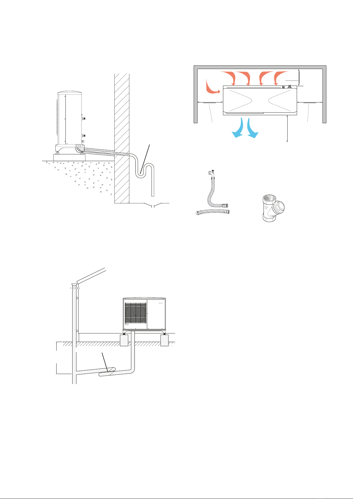
Condensation run off
Condensation water trough
The condensation water trough is used to collect and lead
away condensation water from the heat pump.
NOTE
It is important to the heat pump function that
condensation water is led away and that the
drain for the condensation water run off is not
positioned so that it can cause damage to the
house.
NOTE
Pipe with heating cable for draining the con-
densation water trough are not included.
NOTE
To ensure this function the accessory KVR 10
should be used.
NOTE
The electrical installation and wiring must be
carried out under the supervision of an author-ised
electrician.
NOTE
Self regulating heating cables must not be
connected.
Caution
If none of the recommended alternatives is
used good lead off of condensation water must
be assured.
႑ The condensation water (up to 50 litres/day) collec-
ted in the trough should be routed by pipe to an
appropriate drain, it is recommended that the
shortest outdoor stretch possible is used.
႑ The section of the pipe that can be affected by frost
must be heated by the heating cable to prevent
freezing.
႑ Route the pipe downward fromJAMA Inverter.
႑ The outlet of the condensation water pipe must be
at a depth that is frost free or alternatively indoors
(with reservation for local ordinances and regula-
tions).
႑ Use a water trap for installations where air circula-tion
may occur in the condensation water pipe.
႑ The insulation must be tight against the bottom of
the condensation water trough.
Drain pan heater, control
The drain pan heater is supplied with power when one of
the following conditions is met:
1. Operating mode "Heating" or "Hot water" is activ-
ated.
2. The compressor has been in operation for at least 30
minutes after last start.
3. The ambient temperature is lower than 1 C.
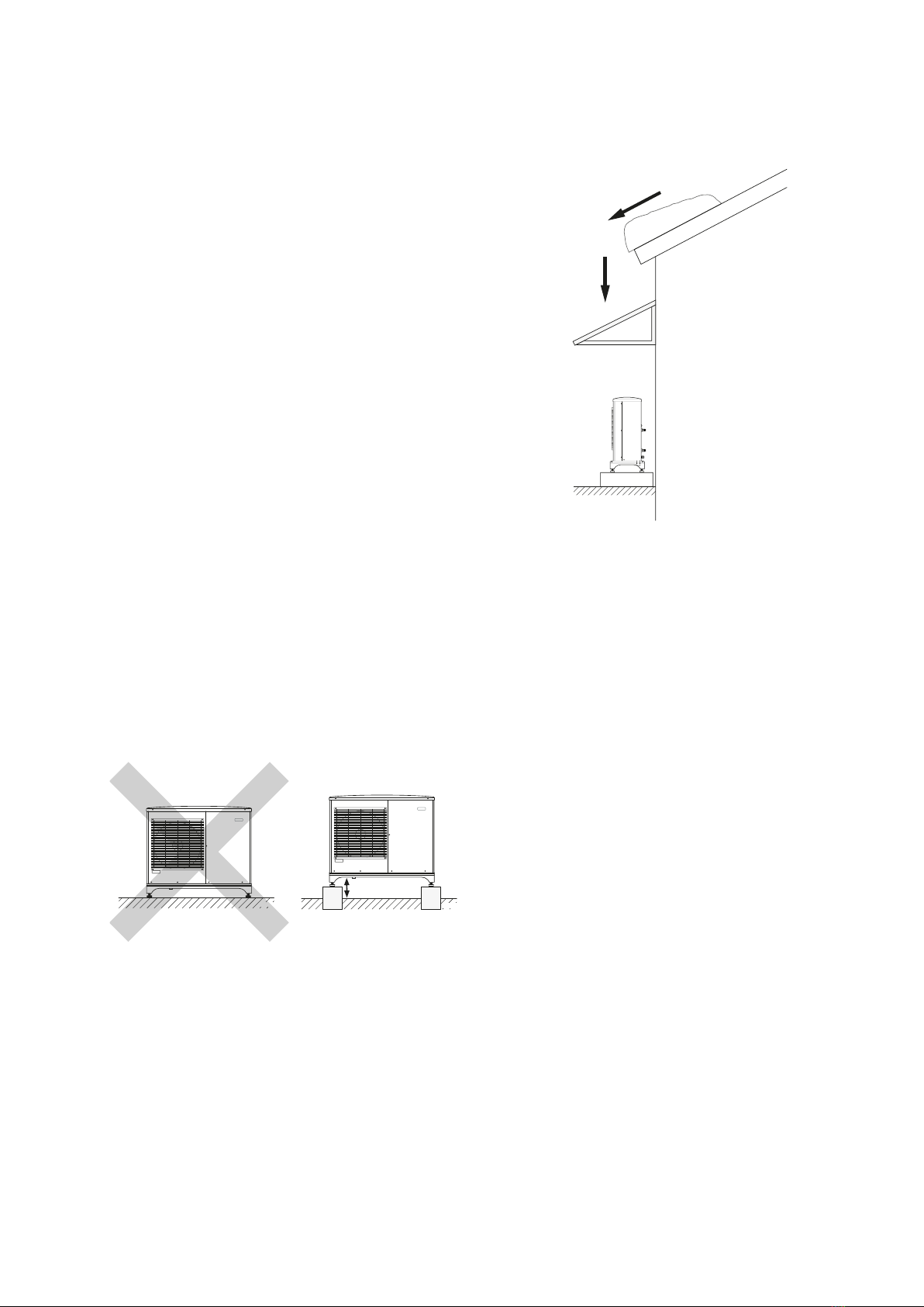
Recommended alternatives Stone
caisson
LEK
FrFrostfritost prt oof depth
If the house has a cellar the stone caisson must be po-
sitioned so that condensation water does not affect the
house. Otherwise the stone caisson can be posi-tioned
directly under the heat pump.
The outlet of the condensation water pipe must be at frost
free depth.
7
Chapter 2 | Delivery and handling

Drain indoors
Water seal
The condensation water is lead to an indoor drain
(subject to local rules and regulations).
Route the pipe downward from JAMA Inverter.
The condensation water pipe must have a water seal to
prevent air circulation in the pipe.
Gutter drainage
Frostfritt
djup
LEK
Frost proof depth
Water seal
The outlet of the condensation water pipe must be at frost
free depth.
Route the pipe downward from JAMA Inverter.
The condensation water pipe must have a water seal to
prevent air circulation in the pipe.
Installation area
The distance between JAMA Inverter and the house wall
must be at least 150 mm. Clearance in front of JAMA
Inverter should be at least one metre.
3000 mm
400 mm
Minimalt
fritt utrymme
Minimalt
fritt utrymme
Fritt utrymme
framför
150 mm
Fritt
utrymme
bakom
600mm
Minimum
free space
Minimum
free space
Free
space
behind
400 mm 600 mm
150 mm
3000 mm
Free space
in front
Supplied components
LEK
Particle filter R25 (HQ1).
2 flexible hoses (R25) with 4
seals
Chapter 2 | Delivery and handling
8

Removing the covers
JAMA Inverter M8
LEK
JAMA Inverter M12/JAMA Inverter M16
LEK
LEK
Removing the front panel
JAMA Inverter M8
LEK
HQ1
9
Chapter 2 | Delivery and handling

JAMA Inverter M12
LEK
HQ1
JAMA Inverter M16
LEK
Removing the side panel
JAMA Inverter M12
LEK
JAMA Inverter M16
D ATA
LEK
Chapter 2 | Delivery and handling
10

General
JAMA Inverter M8
LEK
GQ1
F
DH
UB3
EP1
X1
EB11
CM
20S
63H1
LPT
SM2
SM1
FM01
PWB2 PWB3 PWB1
BT12
BT15
BP4
QN2
BT3
PF3
HS1
EP2
GQ10 QN1
BP2
QM35
QM36
BP1
QN3
CH
EB10
LEK
DATA
XL2
UB1
UB2
W1
XL1
UB3
LEK
DATA
PF1PF3
11
Chapter 3 | The heat pump design
3 The heat pump design

JAMA Inverter M12
LEK
QN1
GQ1
GQ10 QM35
QN3
QM36
TB
BP1
QN2
PWB1
PWB2
PWB3
DH
UB3
BT3
BP4
PF3
BT15
EP1
EP2
HS1
BP2
BT12
X1
EB11
CM
20S
63H1
LPT SM2
SM1
FM01
CH
EB10
LEK
DATA
XL2
UB1
UB2
W1
XL1
UB3
LEK
D ATA
PF3 PF1
Chapter 3 | The heat pump design
12

JAMA Inverter M16
LEK
GQ1
DH
X1
CM
63H1
CH
SM2
SM1
FM01
PWB2 PWB3 PWB1
QN2 20S
BT12
TB
BP1
PF3
QN3
BP4
BT3
BT15
UB3
GQ10 HS1EB10
QN1
EP2
QM36
QM35
EB11
GQ2 FM02
EP1
F
LPT
BP2
13
Chapter 3 | The heat pump design

LEK
DATA
XL2
UB1
UB2
XL1
UB3
W1
LEK
DATA
PF3 PF1
Chapter 3 | The heat pump design
14

List of componentsJAMA Inverter M8, M12, M16
Pipe connections
QM35
QM36
Service valve, liquid side
Service valve, gas side
Connection, heating medium out of JAMA Inverter,
XL1
G3/4" (Ø22 mm)
Connection, heating medium in to JAMA Inverter,
G3/4" (Ø22 mm)
XL2
Sensors etc.
BP1 (63H1) High pressure pressostat
Temperature sensor, heating medium return
line
BT3
Temperature sensor, condenser supply line
BT12
Temperature sensor, fluid pipe
BT15
BP2 (LPT) Low pressure transmitter
BP4 High pressure sensor
Electrical components
AA23 Communication board
AA23-S2 Dipswitch communication card
AA23-X1 Terminal block, incoming supply
AA23-X4 Terminal block, communication
EB10 (CH) Compressor heater
EB11 (DH) Drip tray heater
FMain fuse compressor unit
Fuse for external heating cable (250 mA),
F3
max 45 W.
GQ1 (FM01)Fan
GQ2 (FM02)Fan
PWB1
PWB2
PWB3
Control board
Inverter board
Filter board
Terminal block, electricity and communica-
TB
tion
Terminal block incoming
X1
Cooling components
QN2 (20S) 4-way valve
GQ10 (CM) Compressor
QN3 (SM1) Expansion valve, cooling
QN1 (SM2) Expansion valve, heating
Evaporator (air coil, copper pipe with alumini-
EP1
EP2
um flange)
Condenser (ACH 30, copper/stainless steel)
Drying filter
HS1
Miscellaneous
Type plate
PF1
PF3
UB1
UB2
Serial number
Cable gland, incoming supply Cable
grommet, communication Cable
grommet, heating cable (EB14)
UB3
Cable, incoming supply
W1
15
Chapter 3 | The heat pump design

Electrical connection
Electrical components
AA23 Communication board
AA23-S2 Dipswitch communication card
AA23-X1 Terminal block, incoming supply
AA23-X4 Terminal block, communication
EB10 (CH) Compressor heater
EB11 (DH) Drip tray heater
FMain fuse compressor unit
Fuse for external heating cable (250 mA),
F3
max 45 W.
GQ1 (FM01)Fan
GQ2 (FM02)Fan
PWB1
PWB2
PWB3
Control board
Inverter board
Filter board
Terminal block, electricity and communica-
TB
tion
Terminal block incoming
X1
JAMA Inverter M8
LEK
AA23
F3
AA23-X4
AA23-X1
AA23-S2
Chapter 3 | The heat pump design
16

JAMA Inverter M12
LEK
EB11
PWB3 PWB1
EB10
AA23
FM01TB
F
F3
AA23-X4
AA23-X1
DH
CH
GQ1
AA23-S2
LEK
PWB2
17
Chapter 3 | The heat pump design

JAMA Inverter M16
LEK
PWB3 PWB1
EB10
FM01
AA23-X4
DH
CH
GQ1
TB
AA23-X1 F3
EB11
F
AA23 AA23-S2
LEK
PWB2
Chapter 3 | The heat pump design
18
This manual suits for next models
2
Table of contents
Popular Heat Pump manuals by other brands

ClimaCool
ClimaCool SHC onDEMAND Series Installation operation & maintenance

Nordic
Nordic W Series Product application, installation and service manual

Daikin
Daikin EGSQH10S18AA9W installation manual

Mitsubishi Electric
Mitsubishi Electric PUHZ-W85VAA Service manual

Ingersoll-Rand
Ingersoll-Rand ENL 10 Instructions for installation and operation

Nordic
Nordic W Series Application, Installation & Selection Guide