J&E Hall JABC-1 User manual

JABC-1
AMBIENT BEVERAGE COOLER
ISSUE: 01.03.2016
CE
LLAR COOLER
RANGE
TECHNICAL MANUAL

Issue: 01.03.2016 Pa e 2
Contents
1. Nomenclature
3
2. Standard Product Confi uration
3
3. Product Description
3
4. Specification
4
5. Box Contents
4
6. Operation
4
7. Health & Safety
5
8. Airflow Calculations
6
9. Installation
7-9
10. Commissionin
10
11. Dimensional Drawin
11
12. Wirin Dia ram
12
13. Service & Maintenance
13
14. Troubleshootin
14
15. Certification
15

Issue: 01.03.2016 Pa e 3
1. Nomenclature
1: 1
st
Generation
JABC: J & E Hall Ambient Beverage Cooler
2. Standard roduct Configuration
•Refri erant free – environmentally conscious
•Washable/reusable air filter
•EBM fan motor with multi-speed capability – can be adjusted to suit room size
•Interchan eable air inlet damper location – either rear or base mountin
•Standard 150mm diameter ductin diameter
•Fully pre-set controllers
•Inbuilt timer to allow cellar cooler to run for 1 hour per day (winter operation)
•Switchin relay allows operation with all types of cellar coolers
3. roduct Description
The JABC-1 is primarily used for coolin beer cellars. Cold air is drawn from outside by the fan throu h the washable air filter and
distributed into the cellar space. The unit consists of a fan motor, washable filter, controllers, air damper, a pre-wired electrical
control box all housed within a powder coated steel casin . Operation is via two electronic temperature controls – one an ambient
controller and the other a cellar controller. Each controller has one temperature probe – the ambient probe bein positioned outside
by the air intake rille and the cellar probe bein positioned in a suitable position within the cellar space (ideally by the main cellar
cooler temperature sensor). This uideline enables users to ensure correct and safe installation, operation and maintenance of this
product.
JABC- 1

Issue: 01.03.2016 Pa e 4
4. Specifications
Model Fan Motor Speed Air Flow
(m³/h) Sound
dB(A) @ 1m
Type Max Current (A)
JABC-1 D2E146-HT5902 1.28A
4 684 69.8
3 576 65.0
2 468 56.4
1 252 43.8
Model Overall Dimension (mm)
Mounting Dimensions (mm)
Dry Weight (kg)
W D H W D
12
JABC-1
349 381 484
(Refer drawing- Page 8 )
5. Box Contents
The followin items are included:
•1no. Ambient Cooler
•1no. 2m mains supply cable (without plu )
•2no. Bracket supports
•2no. M5 screws
•1no. Fixin hole template
•2no. Cable lands (1no. M20 & 1no. M12)
•1no. Technical Manual
lease Note: An installation kit is available separately which includes the followin items:
•1no. 500mm len th of 150mm Ø plastic ductin
•1no. External air rille
•2no. Internal door rilles
•1no. Spare air filter
6. Operation
The JABC unit is desi ned to operate when the external ambient temperature is 8°C or below and the cellar temperature rises
above its setpoint of 10°C. The JABC fan motor will draw external cool air into the cellar – passin throu h the air filter and coolin
the space until the set temperature of 10°C is reached. If the cellar temperature continues to rise with the JABC unit runnin , at 13°C
the main cellar cooler unit will cut in and run alon with the JABC to provide additional coolin until the setpoint temperature is
reached. At this point, both the JABC and the main cellar cooler will cut off. The JABC unit will not operate if the external ambient
temperature is above 8°C. At external ambient temperatures of above 8°C, only the main cellar cooler system will operate.
The JABC unit is desi ned to be the main control for the cellar temperature, utilizin both external air when available and the main
cellar cooler as required. The main cellar cooler controller should be set to the same operatin temperature as the JABC unit.
An inbuilt timer within the controller allows the main cellar cooler to run for one hour every 24 hours. This ensures that the main cellar
cooler will still run durin winter periods.

Issue: 01.03.2016 Pa e 5
7. Health and Safety
General information
Before Installation
•On receipt of the product, all items should be visually inspected and any dama e or shorta e should be advised to the supplier
immediately.
•Ensure that the correct volta e supply is available for the unit requirement. Dama e to electrical components within the unit will
occur if this is not observed.
•Check that the proposed equipment location is suitable and provides adequate support for the wei ht of the unit.
•Check the proposed equipment location for mains services ( as, electric water etc.) before drillin holes for ventilation duct and
unit fixin s.
•If usin external ductin arran ement, ensure ductin route will fall within the limitation of pressure resistance as noted on pa e
6.
During Installation and subsequent maintenance
•Installation and maintenance are to be performed only by qualified personnel who are familiar with local codes and
re ulations, and experienced with this type of equipment.
•If liftin equipment is required, ensure that it is suitable for purpose, certificated and that the operatives are qualified to use it.
•Safe workin methods are identified and operatives have suitable Personal Protective Equipment (PPE).
•Ensure the workin area is clear of obstructions.
•The units contain movin parts and electrical power hazards, which may cause severe injury or death. Disconnect and shut off
power before installation or service of the equipment.
•Units must be earthed.
•The electrical covers and fan uards must remain fitted at all times.
•Use of the units outside of the desi n conditions and the application for which the units were intended may be unsafe and be
detrimental to the units, re ardless of short or lon term operation.
•The units are not desi ned to withstand loads or stresses from other equipment or personnel. Such extraneous loads or stress
may cause failure or injury.
Important Note:
Only qualified and authorized personnel, who are familiar with refri eration systems and components
includin all controls, should perform the installation and start-up of this equipment. To avoid potential
injury, use care when workin around sharp ed es of metal cabinets. All electrical wirin should be
installed in accordance with all applicable codes, ordinances and local by-laws. No work should be
undertaken on any equipment without first ensurin all electrical supplies are isolated.
lease be aware that during operation, even if the JABC unit is electrically isolated at its own
supply, there may be terminals within it which are still LIVE. Ensure that the source of the supply is
also isolated before attempting any service or maintenance operations.
Issue: 01.03.2016 Pa e 6
8. Air Flow Calculations
For effective operation, the cellar will require between 6 to 10 air chan es per hour. To calculate the fan speed settin needed to
achieve the required air chan e:
•Calculate room volume in m³ (L x W x H)
•Multiply the resultin room volume by a value between 6 and 10 (air chan es/hour) to achieve a required fi ure in m³/h.
•Check the fi ure a ainst the airflow values (m³/h) for the fan iven in Section 4 on pa e 4 and select the fan speed which
best matches this.
The JABC unit comes with a rear entry air inlet connection for direct attachment to an external facin wall (throu h-wall installation).
If an external facin wall is unavailable, the JABC unit can be mounted in a suitable location, with the air inlet connection chan ed to
bottom entry. This is done by exchan in the rear inlet spi ot with the bottom entry sealin plate for ductin purpose. Please see
pa e 7 for instructions on how to chan e the inlet spi ot position.
When connectin ductin to the JABC unit, it is recommended that any increase in pressure resistance should be limited as follows:
Fan Speed
Maximum Pressure Resistance (Pascals)
4
90
3
118
2
114
1
60
For 150mm nominal diameter li htwei ht ductin , the followin standard industry values can be used to calculate the pressure
resistance for the proposed ductin run:
150mm Circular Duct
Pressure Resistance (Pascals)
1 metre strai ht len th
7
1no. 90 de ree bend
15
1no. 45 de ree bend
7.5
Example calculation:
Room volume is 6m x 5m x 2.4m (72m³). Multiply this fi ure by 8 (air chan es/hour). This ives a required fi ure of 576m³/h. Either
fan speed 3 or 4 will ive the required airflow to achieve 8 air chan es per hour.
Installation requires: 6m of strai ht ductin , 2no. 90 de ree bends and 2no. 45 de ree bends
Calculation: (6 x 7 Pascals) + (2 x 15 Pascals) + (2 x 7.5 Pascals) = 87 Pascals
Assessment: 87 Pascals resistance is within the limits of the fan at either fan speed 3 or fan speed 4.
lease Note:
Fan speed 1 should only be used for throu h-wall applications with small room sizes. For extended ductin application, we do not
recommend usin the unit with fan speed 1. Re ardless of room size, please select either fan speed 2, 3 or 4 only.

Issue: 01.03.2016 Pa e 7
9. Installation
•Chan in Air Spi ot Position
Before installation of the unit, follow these steps to chan e the position of the air spi ot.
Front view inside cellar room Side view showin air inlet hole
throu h wall
1.
Remove
blankin
plate from the
bottom of the unit.
2. Unscrew the damper and
interchan e the damper from
rear to bottom of unit from
inside.
3. Screw the damper to bottom
panel usin existin M5 screws.
4. Cover the hole in rear panel
usin plate and fix usin the
existin M4 screws.
DAMPER
PLATE
M5 SCREW
M4 SCREW
Important Note
s
:
1. Ensure that the outside wall is clear from any obstructions
2. Ensure that the selected wall is stron enou h to support the unit.
3. Ensure that no other exhausts will blow directly into the air inlet duct.
4. Ensure that all hidden cablin /pipework are checked for before any drillin commences.
5. Ensure that fixin s are suitable for the application.
6. Do not position the unit directly opposite the airflow from the main cellar cooler.
Issue: 01.03.2016 Pa e 8
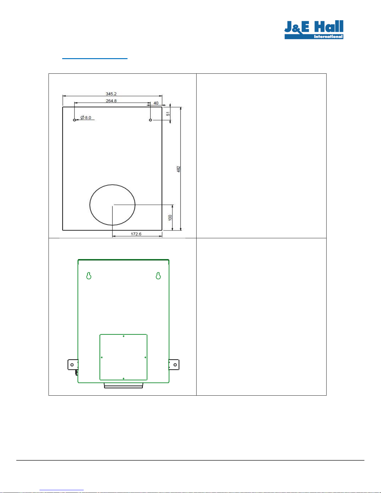
9. Installation
Wall dril
lin
s for direct ductin of
unit.
1. Drill the wall fixin points and the hole
for the air inlet duct, followin the
dimensions as shown on the left or
follow template supplied.
2. Recommended drill dimension is 157mm
diameter for the air inlet duct.
3. Attach required len th of 150mm Ø
ductin to air spi ot and seal joint with
duct tape or silicon.
4. Pass ambient air probe down inside of
ductin . Coil and cable tie excess cable
neatly.
5. Remove the top cover of unit for access
to fixin holes, and fix to wall.
6. Fix the 2 brackets, one each side of unit
usin M5 screws and fix to wall.
7. Seal ductin to hole and fix external air
rille to ductin .
8. Position ambient air sensor.
Alternative mountin
arran ement for
ambient cooler
Spi ot can be placed at bottom of unit to
enable external ductin to be used. This is
the alternative arran ement of the unit
where the rear hole is blanked by plate.
Note :
1. The hole throu h wall can be drilled in
another location.
2. Ductin is not provided.
•
Room Air Balance
As the unit can provide up to approximately 700m³/h of airflow into the cellar, this will need to be balanced by allowin air outlet
from the room. This can be done by fittin an air rille in the cellar door (provided in the optional installation kit) or by other means.
Issue: 01.03.2016 Pa e 9
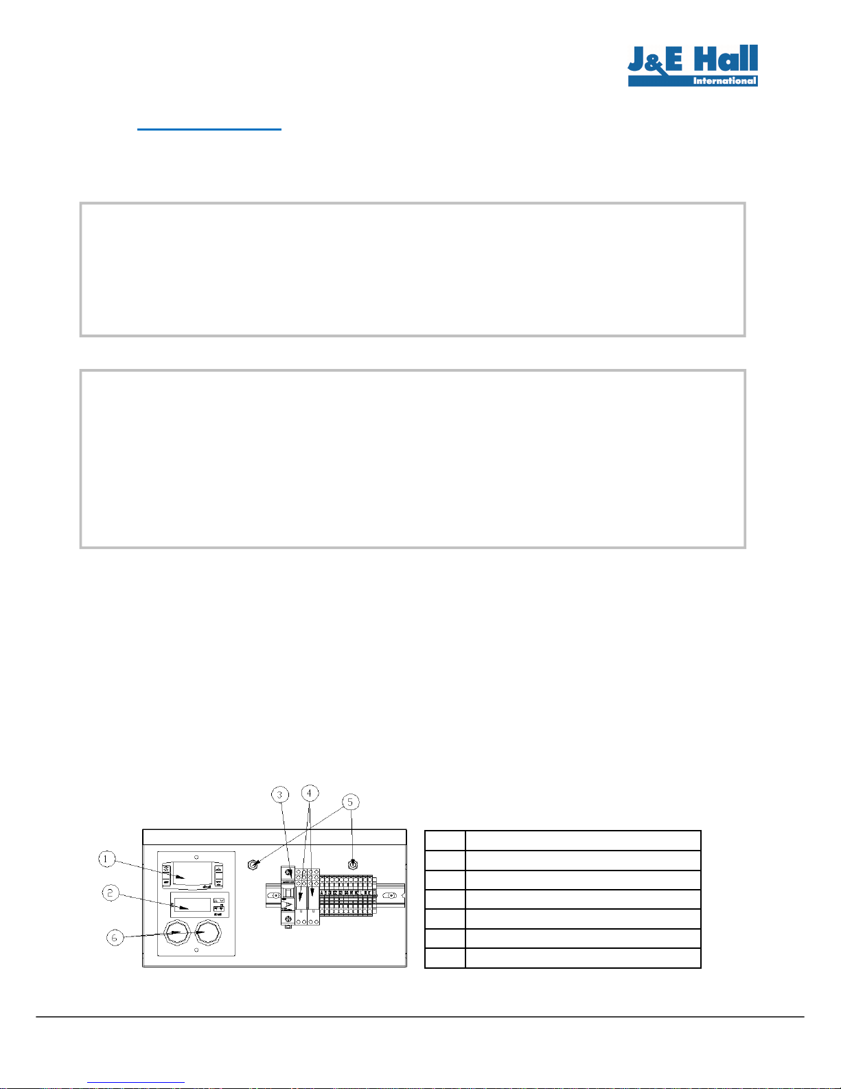
9. Installation
Electrical Connection & Probe Positionin
1. Cable lands are provided for the mains supply cable and the cellar temperature probe cable on the ri ht hand side of the
unit. Use the M20 land for the mains supply cable and the M12 land for the cellar temperature probe.
2. The cellar temperature probe is coiled up in the control box. Remove the front lower panel on the unit to ain access to the
control box.
3. The ambient temperature probe is coiled and stored behind the air damper on the rear of the unit.
4. Connect the mains supply cable (provided) to the unit as per the dia ram on pa e 12. Do not switch on the supply yet.
5. Isolate the main cellar cooler supply and break the control circuit as per the dia ram on pa e 12. Usin a 2 core cable,
connect the control circuit from the main cellar cooler to terminal A on the JABC unit and return via terminal B to feed either
the main cellar cooler contactor coil or the solenoid valve.
6. Position the JABC cellar temperature probe unit in a suitable position within the cellar (ideally next to the temperature sensor
for the main cellar cooler). The probe cable len th is 3m but this can be extended if required.
7. Position the JABC ambient temperature probe. This can be run down the inside of the air inlet ductin and secured within the
external air inlet rille. Ensure sensor is protected from direct sunli ht which may affect the temperature readin and the
operation of the unit.
Item
Description
1 CONTROLLER (AMBIENT)
2 CONTROLLER (CELLAR)
3 MCB
4 RELAYS
5 CABLE GLANDS
6 PILOT LAMPS
Important Note
s
:
1. Ensure that all power supplies have been isolated before startin any electrical work.
2. Only a qualified electrician should carry out any electrical work.
3. Ensure that indoor cellar unit is fully isolated before carrying out this section.
4. Make sure that the supply to the JABC-1 unit and the control circuit from the main cellar cooler
are usin the same electrical phase, otherwise there is potential for 400V at the JABC-1 unit.
5. The main cellar unit evaporator fan(s) should run when the JABC unit is runnin to ensure proper
air circulation within the cellar. This may require a wirin chan e on the main cellar unit.
Important Note:
The mains electrical supply to the JABC-1 unit must be via a suitably rated isolator and circuit breaker
or fuse. There is no isolator fitted to the unit. It requires a 230 volt / 1 phase / 50Hz supply which must
include a Neutral and Earth. It is not suitable for any other supply volta es (other than a deviation of
+/- 10% of the above values) and is not suitable for 60 Hz supplies.

Issue: 01.03.2016 Pa e 10
10. Commissioning
1. Switch on power supply to both main cellar unit and JABC-1.
2. The JABC-1 unit should now display outside ambient temperature on the Ambient controller (top) and the cellar temperature
on the Cellar controller located below.
3. The cellar temperature set point of the JABC-1 unit is preset to 10°C. This must not be altered.
4. The temperature set point of the main coolin should be set at 10°C to match the JABC controller or it can be set 1°C lower
than JABC-1 settin if required. The set point of the main cellar cooler should not be set above 10°C.
5. Allow the system to run and ensure that the unit is functionin correctly.
There are 2 external status li hts on the front of the JABC-1 unit ivin a clear visual display of current operatin condition of unit.
ilot Light Colour
Operating Condition
Green
JABC Fan Motor operat
in
Yellow
Main cellar coolin
function is called for
* Illumination of the Yellow light for main cellar cooling does not mean that the system is running, just that the main cellar
cooling function has been called for.
Controller Alarm Display Information
Ambient Controller
Error Code
Cause
P1
Room probe failure
P2
Evaporator probe failure
HA
Maximum
temperature alarm
LA
Minimum temperature alarm
Cellar Controller
Error Code
Cause
PFo
Probe broken or missin
PFc
Probe short circuited
HA
Maximum temperature alarm
LA
Minimum temperature alarm
Important Note:
1. Ensure that all covers are fitted on the unit.
2. Ensure that all electrical connections have been made as per the wirin dia ram on pa e 12.
3. The controllers are fully preset and the settin s should not be altered.
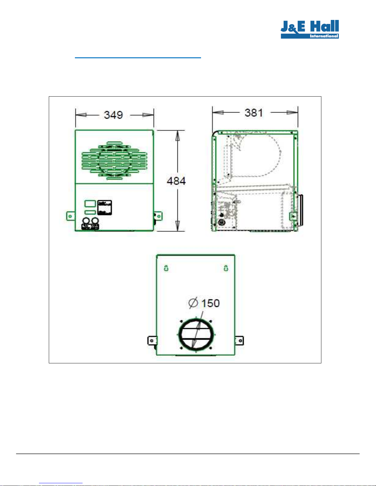
Issue: 01.03.2016 Pa e 11
11. Dimensional Drawing
Issue: 01.03.2016 Pa e 12
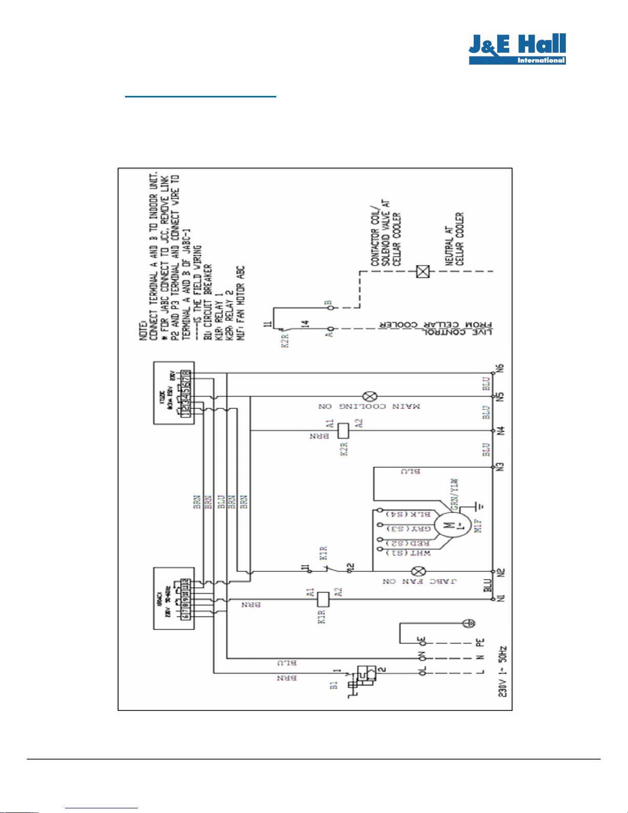
12. Wiring Diagram

Issue: 01.03.2016 Pa e 13
13. Service & Maintenance
The units are desi ned to ive lon life operation with minimum maintenance. However, they should be routinely checked and the
followin service schedule is recommended under normal circumstances:
The front panels and control panel need to be removed to ensure all parts / components mentioned below are accessible:
1. Fan Motor– Inspect at re ular intervals
•Check for abnormal noise and vibration.
2. Power Supply – Inspect at re ular intervals
•Check the runnin current and volta e for the unit.
•Check the electrical wirin and reti hten connections as necessary.
3. Filter – Clean and inspect at re ular intervals
•Check and clean the filter at 3 months intervals to remove dirt and debris on filter media.
•Check external air inlet rille for obstructions.
4. Controls
•Check accuracy of temperature readin s.
Unit decommissioning and disposal
•At the end of the unit’s useful life, a suitably qualified person should decommission it. The unit components must be disposed
of or recycled as appropriate in the correct manner.
Important Note:
Warnin !
–
Disconnect the mains electrical supply before servicin or openin the
units.
Remove this
cover to
access filter
Slide the
filter out

Issue: 01.03.2016 Pa e 14
14. Troubleshooting
In the event of a JABC unit malfunction, please check the followin items. Consult a qualified person before any corrective actions
are taken.
Failure
ossible Causes
Unit does not operate
•Check power supply to unit.
•MCB / safety device tripped.
Air Flow become
s
slower
•Check whether air filter is clo ed with dust.
•Check outside air inlet rille is not blocked.
• Check whether fan speed has been altered.
Error messa e on either of
temperature controllers •Controller/temperature probe failed. Call Service En ineer.

Issue: 01.03.2016 Pa e 15
15. Certification

Issue: 01.03.2016 Pa e 16
J & E Hall Limited
Hansard Gate
West Meadows
Derby, DE21 6JN
En land
Tel: + 44 (0) 1332 253400
Fax: + 44 (0) 1332 371061
Email: helpline@jehall.co.uk
www.jehall.com Issue: 01.03.2016
Other manuals for JABC-1
1
Table of contents
Other J&E Hall Freezer manuals


