Janus 230V 750VA User manual

□
Tower and Rack-Mount
Convertible UPS
User’s Manual
750
/
1000/1500/2200/3000 1
Table of Contents
1Introduction ------------------------------------------------------------------------------------2
2IMPORTANT SAFETY INSTRUCTION-------------------------------------------------3
2.1 An Important Notice------------------------------------------------------------3
2.2 Storage Instruction--------------------------------------------------------------4
3SET UP -----------------------------------------------------------------------------------------5
3.1 Inspection ------------------------------------------------------------------------5
3.2 Place the UPS Properly---------------------------------------------------------5
3.3 Unpacking------------------------------------------------------------------------6
3.4 Selecting Installation Position-------------------------------------------------7
3.5 UPS Setup------------------------------------------------------------------------7
3.6 Tower Setup ---------------------------------------------------------------------8
3.7 Rack-Mount Setup--------------------------------------------------------------9
3.8 UPS Front Panel--------------------------------------------------------------- 11
3.9 LCD Display Panel ----------------------------------------------------------- 12
3.10 UPS Rear Panel --------------------------------------------------------------- 13
4INSTALLATION --------------------------------------------------------------------------- 18
4.1 Connect Utility and Load ---------------------------------------------------- 18
4.2 Connect Network Surge protection----------------------------------------- 19
4.3 Connect Computer Interface Port------------------------------------------- 19
4.4 REPO Switch ------------------------------------------------------------------ 20
5OPERATION-------------------------------------------------------------------------------- 21
5.1 Turn on the UPS -------------------------------------------------------------- 21
5.2 Turn Off the UPS ------------------------------------------------------------- 21
5.3 Plug-in Charge ---------------------------------------------------------------- 21
5.4 Auto-Restart ------------------------------------------------------------------- 22
5.5 Alarm Silence------------------------------------------------------------------ 22
5.6 Self Test------------------------------------------------------------------------ 22
6UPS MAINTENANCE--------------------------------------------------------------------- 23
6.1 Battery Replacement---------------------------------------------------------- 23
6.2 How to Replace Battery------------------------------------------------------ 24
6.3 Recycling the Used battery -------------------------------------------------- 26
7Communication------------------------------------------------------------------------------ 27
7.1 DB-9 Connector--------------------------------------------------------------- 27
8Optional Communication Cards----------------------------------------------------------- 28
8.1 DCE (Dry Contact) card ----------------------------------------------------- 28
8.2 SNMP card of Megatec ------------------------------------------------------ 29
9SPECIFICATIONS ------------------------------------------------------------------------- 30
9.1 120V---------------------------------------------------------------------------- 30
9.2 230V---------------------------------------------------------------------------- 32

2
1 Introduction
The UPS featured with Tower/Rack Convertible design, Single AVR Boost
and Single Buck, Pure Sine Wave Output, User’s Friendly LCD Display, Built-in
customer Option Slot, Hot Swappable Battery, and USB/RS232 Communication
interface, provides a flexible from factor for most of business critical file server,
minicomputers, network switches and hubs, etc. in tower or rack mount formats.
zSine Wave Output provides assurance of compatibility with all kinds of loads.
zUser’s Friendly LCD panel may display system status including load level,
battery level, AVR-Boost/Buck and fault status for easy service.
z90% High Efficiency in Normal Mode meets high energy saving standard
and reduces noise and heat generated by other topology UPS.
zEasy Swappable Battery Function may save the time and money by
swapping the batteries by end-user without sending it back for a factory
service.
zCold Start Function enables to turn on the UPS without connecting to the
Utility.
zOptional Communication Software allows not only the control of the UPS
and graceful shutdown when the Utility Fails, but also allows the user to
remotely test the major operating functions of the UPS, communicate via
SNMP/web/network optional card, access UPS functions via the web and
alert users via SMS messages against specific events.
zUser-friendly Plug and Play design can easily be installed by end user. All
units up to 3KVA are supplied with input cables and output sockets as
standard.
zPlug-and-play USB/RS232 interface conveniently offers a plug-and-play
USB or RS232 port for connecting with nowadays IT products.
3
2 IMPORTANT SAFETY INSTRUCTION
2.1 An Important Notice
1.The UPS has its own internal energy source (battery). Should the battery
be switched on when no AC power is available, there could be voltage at
the output sockets.
2. Make sure that the AC Utility outlet is correctly grounded.
3. Do not open the case, as there are no serviceable parts inside. Your
warranty will be void.
4. Do not try to repair the unit yourself; contact your local supplier or your
warranty will be void.
5. Please make sure that the input voltage of the UPS matches the supply
voltage.
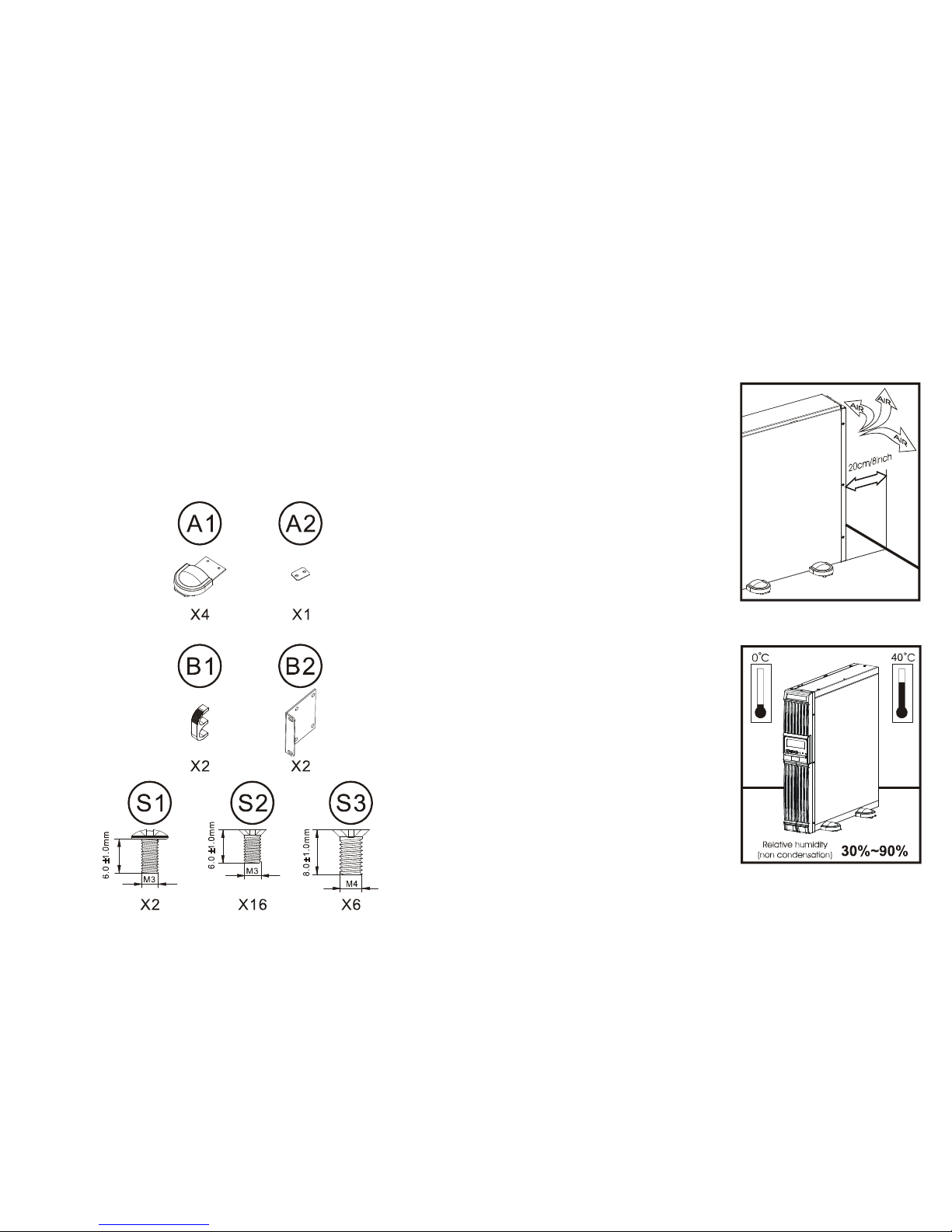
6. To eliminate any overheating of the UPS, keep all ventilation openings free
from obstruction, and do not store "things" on top of the UPS. Keep the
UPS 30 cm away from the wall.
7. Make sure the UPS is installed within the proper environment as specified.
(0-40℃and 30-90% non-condensing humidity)
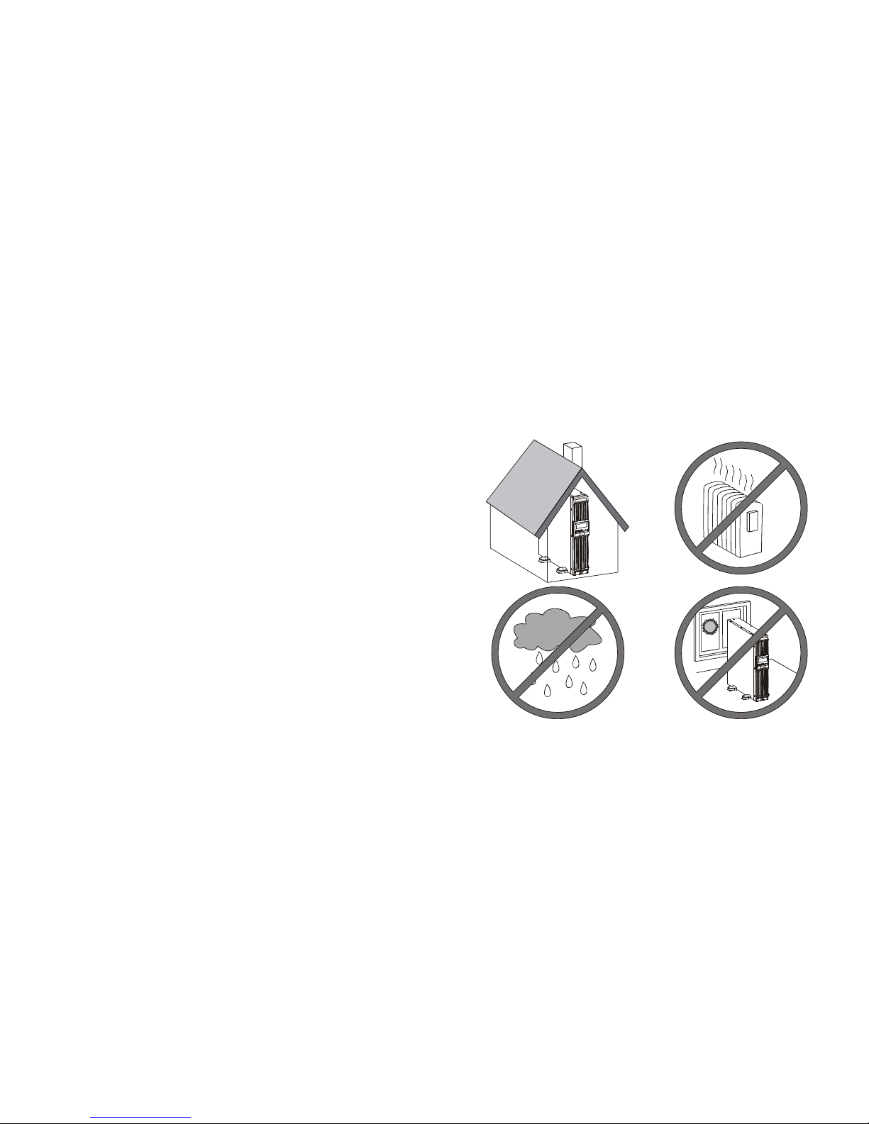
8. Do not install the UPS in direct sunlight. Your warranty may be void if the
batteries fail.
9. Install the UPS indoors as it is not designed for installation outdoors.
10. Dusty, corrosive and salty environments can do damage to any UPS.
11. Install the UPS away from objects that give off excessive heat and areas
that are excessively wet.
12. If liquids are split onto the UPS or foreign objects dropped into the unit,
the warranty will be null and void.
13. The battery will discharge naturally if the system is unused for any length
of time.

4
14. It should be recharged every 2-3 months if unused. If this is not done,
then the warranty will be null and void. When installed and being used, the
batteries will be automatically recharged and kept in top condition.
15. This UPS supports electronic equipment in offices, telecommunications,
process control, medical and security applications. Non-authorized
technician is not allowed to install the UPS in the following areas:
a. Medical equipment directly related to human life
b. Elevator, Metro (Subway) system or any other equipment related to
human safety.
c. Public system or critical computer systems.
16. Do not install the UPS in an environment with sparks, smoke or gas.
17. Make sure the UPS is completely turned off when moving the UPS from
one place to another. It might cause electrical shock if the output is not cut
completely.
18. SAVE THESE INSTRUCTIONS – This Manual Contains Important
Instructions that should be followed during Installation and Maintenance of
the UPS.
19. Symbol for ON/Off is displayed and defined.
20. Intended for installation in a temperature-controlled, indoor area free of
conductive contaminants.
21. Maximum ambient temperature 40℃(or 0~40℃for ambient Operating).
2.2 Storage Instruction
For extended storage through moderate climate, the batteries should be
charged for 12 hours every 3 months by plugging the UPS power cord into the
wall receptacle and turn on input breaker on front panel. Repeat this procedure
every 2 months under high temperature environment.
5
3 SET UP
3.1 Inspection
Inspect the UPS upon receipt. Notify the carrier and dealer if there is damage.
The package is recyclable; save it for reuse or dispose of it properly.
3.2 Place the UPS Properly
The UPS is with microprocessor control, which shall be placed in a well-
ventilated & low humid environment.

6
3.3 Unpacking
1. Take the UPS out of the PE foam.
2. Remove the packing materials.
3. Standard Package includes:
a. User's Manual
b. 1pc x AC Input Power Cord ( Not available for hard wiring connection
models)
c. (1pc for 750/1k/1.5kVA, 2pcs for 2.2k/3kVA)x IEC output cables ( for the
UPS with IEC sockets only)
d. 1set x UPS communication kit (optional)
Accessories for Tower and Rack Mount
7
3.4 Selecting Installation Position
It is necessary to select a proper environment to install the unit, in order to
minimize the possibility of damage to the UPS and extend the life of the UPS.
Please follow the instructions below:
1. Keep at least 20cm(8 inches) clearance
from the rear panel of the UPS from the
wall or other obstructions.
2. Do not block the air-flow to the
ventilation openings of the unit.
3. Please ensure the installation site
environmental conditions are in
accordance with the UPS working
specifications to avoid overheat and
excessive moisture.
4. Do not place the UPS in a dusty or
corrosive environment or near any
flammable objects.
5. This UPS is not designed for outdoor
use.
3.5 UPS Setup
The UPS offers a flexible form factor
enabling integration into a wide variety of
environments.
The UPS with space-saving design only
occupy 2U for 1000 to 3000VA.
If you are installing the UPS in a tower,
continue to the following section, “Tower
setup” otherwise; continue to “Rack-Mount
setup”.

8
3.6 Tower Setup
Stand alone unit
9
3.7 Rack-Mount Setup
Step1
Step2

10
Step3
Step4
Step5
11
3.8 UPS Front Panel

12
3.9 LCD Display Panel
1. Utility LED
2. Fault LED
3. On Switch
4. Off Switch
5. Battery Replacement
6. Battery Backup LED
7. Battery Low
8. Bypass
9. Utility Low, UPS Boost
10. Utility High, UPS Buck
11. UPS Output Indicator
12. Polarity Error or Ground Fault
13. Overload
14. Load/Battery Level (%)
15. Load/Battery Level Indication Control Button
13
3.10 UPS Rear Panel
1000 / 1500VA 120V
Item Description
1 Data Line Connectors
2 Voltage Configuration Switch
3 USB Port
4 RS232 (DB-9) Port
6-1 NEMA 5-15R Output Receptacles
7 Cooling Fan
8 12A Input Circuit Breaker (1000 model only)
15A Input Circuit Breaker (1500 model only)
9 NEMA 5-15P Input Power Core
10 REPO
11 Intellislot Port

14
2200VA 120V(1920VA/1920W for UL)
Item Description
1 Data Line Connectors
2 Voltage Configuration Switch
3 USB Port
4 RS232 (DB-9) Port
5-1 15A Output Circuit Breaker for 6-1
5-2 20A Output Circuit Breaker for 6-2
6-1 NEMA 5-15R Output Receptacles
6-2 NEMA 5-20R Output Receptacles
7 Cooling Vents
8 30A Input Circuit Breaker
9 NEMA 5-20P Input Power Core
10 REPO
11 Intellislot Port
15
3000VA 120V
Item Description
1 Data Line Connectors
2 Voltage Configuration Switch
3 USB Port
4 RS232 (DB-9) Port
5-1 15A Output Circuit Breaker for 6-1
5-2 20A Output Circuit Breaker for 6-2
6-1 NEMA 5-15R Output Receptacles
6-2 NEMA 5-20R Output Receptacles
6-3 NEMA 5-30R Output Receptacles
7 Cooling Vents
8 30A Input Circuit Breaker
9 NEMA L5-30P Input Power Core
10 REPO
11 Intellislot Port

16
750/ 1000/ 1500VA 230V
Item Description
1 Data Line Connectors
2 Voltage Configuration Switch
3 USB Port
4 RS232 (DB-9) Port
6 IEC-320-C13 Output Receptacles
7 Cooling Fan
8 7A Input Circuit Breaker (750 model only)
8A Input Circuit Breaker (1000 model only)
10A Input Circuit Breaker (1500 model only)
9 IEC-320-C14 Input Socket
10 REPO
11 Intellislot Port
17
2200/ 3000VA 230V
Item Description
1 Data Line Connectors
2 Voltage Configuration Switch
3 USB Port
4 RS232 (DB-9) Port
5-1 10A Output Circuit Breaker for 6-1
5-2 10A Output Circuit Breaker for 6-2
6-1 IEC-320-C13 Output Receptacles
6-2 IEC-320-C13 Output Receptacles
6-3 IEC-320-C19 Output Receptacles
7 Cooling Vents
8 15A Input Circuit Breaker(2200 model only)
20A Input Circuit Breaker(3000 model only)
9 IEC-320-C20 Input Socket
10 REPO
11 Intellislot Port

18
4 INSTALLATION
4.1 Connect Utility and Load
First, connect the UPS with Utility, then plug the loads into the Outlets on the
rear of the UPS. To use the UPS as a master “On/Off” switch, make sure that all
of the loads are switched “on”.
These UPS outlets provide battery backup and surge protection to the
equipment when Utility voltage is out of window.
Caution---
Do not connect a laser printer to the UPS outlets!
19
4.2 Connect Network Surge protection
Connect a 10 base-T / 100 base-T network cable with the RJ-45 network
surge protection “IN” jack on the rear of the UPS. Connect from the “OUT” jack
with network cabling to network equipment.
4.3 Connect Computer Interface Port
Connect the supplied interface cable (RS-232 or USB, Optional) between the
interface port on the rear of the UPS and the computer interface port. See
software installation guide in the CD-ROM (Optional) for installation purpose.

20
4.4 REPO Switch
The UPS is equipped with an Emergency Power Off (EPO) switch. The user
must supply a means of interfacing with the EPO circuit to allow disconnecting
the UPS input feeder breaker to interrupt all sources of power to the UPS and
connected equipment to comply with national and local wiring codes and
regulations.
1 2 1 = REPO+
2 = Ground
Short Pin 1 and Pin 2 to enable the REPO function
21
5 OPERATION
5.1 Turn on the UPS
1. Connect the UPS to the wall receptacle. LCD will display “OFF”, when
Utility is normal. If there is nothing on the LCD, go to step 3.
2. Press the “On” Switch on the front panel for approximately 3 seconds until
buzzer sounds, then release the “On” Switch to start the UPS. Both the
LCD and Utility LED (Green) are lit. The start-up procedure is completed
and the loads are supplied by the UPS.
3. To cold start the UPS, press the “On” Switch on the front panel for
approximately 3 seconds until the LCD lights up and buzzer sounds, then
release the “On” Switch. The UPS starts operating and Battery Backup
LED (Amber) lights up. The cold start-up procedure is completed and the
loads are supplied by the UPS.
4. The UPS will run under Backup mode and the buzzer alarms every 2
seconds in case of blackout or over/under voltage. On the contrary, If Utility
is back to normal and then the UPS will run under Utility mode and silence
alarm.
5.2 Turn Off the UPS
1. Press the “Off” Switch for at least 3 seconds to turn off the UPS. If you
press the “Off” Switch less than 3 seconds, the UPS will not execute
shutdown command due to insufficient pressing time.
2. In some occasions, the UPS will shut itself down in case of overload,
output short-circuited or battery cutoff point reached in the Backup mode.
3. The UPS will automatically shut off the output and beep for 5 seconds then
completely shut itself down.
5.3 Plug-in Charge
1. If the Input Power Cord is connected to the wall receptacle properly and
the utility is normal, the UPS will start charging automatically without
processing “Turn On” procedure.
2. You have to charge for at least 8 hours every 3 months to avoid from
battery self over-discharge naturally, if the UPS is in an idle condition.

22
5.4 Auto-Restart
If the Input Power Cord is connected to the wall receptacle properly and
Utility is back to normal, the UPS will automatically restart to provide energy to the
output after battery cut.
5.5 Alarm Silence
1. The Alarm might be turned off by pressing the “On” Switch for
approximately 1 second in the “Backup” mode.
2. Unless any other warning or fault condition occurs, the alarm remains at
Silence condition once the “Alarm Silence” is turned off.
5.6 Self Test
1. Under Utility Normal condition, press the “On” Switch for 3 seconds to
execute the Battery Self-test function.
2. In case the battery is normal, it will enter into the Battery Backup Mode for
10 seconds then return to Utility Mode.
3. If the battery voltage is detected lower than set limit, the Battery
Replacement LCD will blink for 5 seconds then extinguish to stop self-
test procedure. And if battery is detected weak or dead, the Battery
Replacement LCD will steadily illuminate.
Caution---
The UPS will remain at “NO” output, if the start-up operation is not
proceeded properly even though the Input Power Cord is connected
to the wall receptacle.
Important Notice---
Plug the UPS onto the wall receptacle to charge the UPS for over 8
hours after initial installation.
Storage ---
Store at -15 to +30 °C (+5 to +86 °F), charge the UPS battery every six
months.
Store at +30 to +45 °C (+86 to +113 °F), charge the UPS battery every
three months
23
6 UPS MAINTENANCE
6.1 Battery Replacement
When the UPS is started up or a self-test is executed, the Battery
Replacement LED might light up due to battery weak or battery dead.
1. When the Battery-Replacement (RED) lights up, you may leave the UPS to
be re-charged for at least 8 ~ 10 hours to see whether the RED LED will be
extinguished after the Self-test function is executed again.
2. In case the RED LED remains unchanged, you may unscrew the Easy
Swappable Battery cover, replace a new battery then push the “On” Switch
to disable the RED LED. Please follow the steps 1-3 to replace the new
battery.
Caution---
The UPS will remain at “NO” output, if the start-up operation is not
proceeded properly even though the Input Power Cord is connected
to the wall receptacle.
Caution---
The battery is heavy, pull the battery out onto flat, stable surface.
Caution---
DO NOT DISCONNECT the batteries while the UPS is in the BACKUP
mode.

24
6.2 How to Replace Battery
STEP 1
STEP 2
25
STEP 3
STEP 4
1000/ 1500VA

26
2200/ 3000VA
6.3 Recycling the Used battery
Contact your local recycling or hazardous waste center for
information on proper disposal of the used battery.
27
7 Communication
7.1 DB-9 Connector
The UPS has a DB-9 (9 pin female) connector on the rear to allow UPS status
communications with a computer running UPS software. The connection
provides serial communication, On Battery and Low Battery signals.
Table 4 DB-9 pin assignment
DB-9 Pin Assignment Description
1Low Battery (open collector)
2UPS TxD
3 UPS RxD
4 N.C.
5 Common
6 N.C.
7 Low Battery (open emitter)
8 Utility Fail (open emitter)
9 Utility Fail (open collector)

28
8 Optional Communication Cards
8.1 DCE (Dry Contact) card
8.1.1 The pin assignments of 10-Pin Terminal
:
1 ÆN/A
2 ÆUtility Abnormal
3 ÆUtility Normal
4 ÆAVR On
5 ÆBattery Low
6 ÆN/A
7 ÆN/A
8 ÆCommon
9 ÆShutdown UPS positive(+ ) signal
10 ÆShutdown UPS Negative( - ) signal
8.1.2 The shutdown function will be activeated, after a +6~+25Vdc is put
between pin 9 and pin 10 for 5 seconds.
8.1.3 The capacity of each relay contact is 40Vdc/25mA.
8.1.4 Installation Position
:
Optional Slot.
8.1.5 Flexible signal output for N.C.(Normal Close) or N.O.(Normal Open)
contact by shorting pin1-2 or pin2-3 form JP1-5.
8.1.6 The shutdown function will be enabled in 1 minute after blackout occurs if
the pin1-2 of both CN1 and CN6 are shorted by cap. Or, the shutdown
function can only be enabled by pin9-10 of CN3 if the pin2-3 of both CN1
and CN6 are shorted by cap.
1 2 3 4 4 5 6 7 8 9 10
29
8.2 SNMP card of Megatec
8.2.1. For installation, please refer to the user’s manual attached with the card.
8.2.2. Installation Position:Optional Slot

30
9 SPECIFICATIONS
9.1 120V
Model number 1000VA 1500VA 2200VA 3000VA
Power Rating, VA/W 1000VA/900W 1500VA/1350W 1920VA/1920W 3000VA/2700W
Dimensions, W x D x H, in (mm)
Unit 440x405x88 440x405x88 440x650x88 440x650x88
Shipping 560x526x228 560x526x228 560x833x228 560x833x228
Weight, lbs (kg) Unit 19.7 21.1 34.6 38.2
Shipping 22.9 24.6 38.3 42
Input AC Parameters
Surge Protection 570J
Voltage Range
Without
Battery Operation 83~159, configurable
Frequency Range 45~65Hz, (±0.5Hz)
Input Power Cord 10ft(3m)
attached,
w/ NEMA 5-15P
10ft(3m)
attached,
w/ NEMA 5-15P
10ft(3m)
attached,
w/ NEMA 5-20P
10ft(3m) attached,
w
/ NEMA L5-30P
Output Receptacles (8) NEMA 5-15R (8) NEMA 5-15R (6) NEMA 5-15R
(2) NEMA 5-20R (6) NEMA 5-15R
(2) NEMA 5-20R
(1) NEMA L5-30R
Voltage (Normal
mode) 110 / 120 / 127 VAC (configurable) ±10%
Voltage (Battery
Mode) 110 / 120 / 127 VAC (configurable);
±5% before low battery warning
Transfer Time 4-6 ms typical
Waveform Sinewave
Frequency
(Normal Mode) 45~65Hz, (±0.5Hz)
Frequency
(Battery Mode) 50/60Hz, (±0.5Hz), auto sensing
Overload Warning >100% - 109% Continuous Overload Alarm and power to the load
>110% - 120% Shutdown after 10 minutes
Normal Mode
>120% Shutdown UPS immediately
>100% - 119% Continuous Overload Alarm till end of battery discharged
>120% - 130% Shutdown after 10 seconds
Battery Mode
>130% Shutdown UPS immediately
Battery Parameters
Type Valve-regulated, nonspillable, lead acid
Quantity x Voltage x
Rating 3x36x7 3x36x9 6x72x7 6x72x9
31
Backup Time
Full Load 3”14 2”33 2”41 2”32
Half Load 10”31 8”18 8”40 8”14
Recharge Time 5 hours to 90% of rated capacity, after full discharge into resistive load
Environmental
Operating
Temperature +32°F to + 104°F (0°C to + 40°C)
Storage Temperature +5°F to + 104°F (-15°C to + 40°C)
Relative Humidity 0% to 95%, non-condensing
Operating Altitude Up to 10,000 ft. (3000m) at 95°F (35°C) without derating
Audible Noise <40 dBA, internal fan(s) Off
<45 dBA, internal fan(s) On <40 dBA, internal fan(s) Off
<45 dBA, internal fan(s) On
Model number PS1000RT3-120 PS1500RT3-120 PS2200RT3-120 PS3000RT3-120
Power Rating, VA/W 1000VA/900W 1500VA/1350W 1920VA/1920W 3000VA/2700W
Agency Safety UL 1778, c-UL Listed
Surge ANSI C62.41 CatA Lev3 (surges)
IEC61000-4-5
ESD IEC61000-4-2
Susceptibility IEC61000-4-3
Electrical Fast
Transient IEC61000-4-4
Emissions FCC Part 15, Class A
Conducted Immunity EN61000-4-6
Harmonics EN61000-3-2
Network surge UL 497 B
Transportation ISTA Procedure 1A Certification

32
9.2 230V
Model number 750VA 1000VA 1500VA 2200VA 3000VA
Power Rating, VA/W 750VA/675W 1000VA/900W 1500VA/1350W 2200VA/1980W 3000VA/2700W
Dimensions, W x D x H, in (mm)
Unit 440x405x88 440x405x88 440x650x88 440x650x88
Shipping 560x526x228 560x526x228 560x770x228 560x770x228
Weight, lbs (kg) Unit 15 19.4 20.9 33.8 37.2
Shipping 18.2 22.6 24.1 38.3 41.5
Input AC Parameters
Surge Protection 220J
Voltage Range
Without
Battery Operation 165~300, configurable
Frequency Range 45~65Hz, (±0.5Hz)
Input Socket IEC-320-C14 IEC-320-C14 IEC-320-C20 IEC-320-C20
Output Receptacles (8)IEC-320-C13 (8)IEC-320-C13 (8)IEC-320-C13
(1)IEC-320-C19 (8)IEC-320-C13
(1)IEC-320-C19
Voltage (Normal
mode) 220/230/240 VAC (configurable) ±10%
Voltage (Battery
Mode) 220/230/240 VAC (configurable);
±5% before low battery warning
Transfer Time 4-6 ms typical
Waveform Sinewave
Frequency
(Normal Mode) 45~65Hz, (±0.5Hz)
Frequency
(Battery Mode) 50/60Hz, (±0.5Hz), auto sensing
Overload Warning
>100% - 109% Continuous Overload Alarm and power to
the load
>110% - 120% Shutdown after 10 minutes
Normal Mode
>120% Shutdown UPS immediately
>100% - 119% Continuous Overload Alarm till end of battery
discharged
>120% - 130% Shutdown after 10 seconds
Battery Mode
>130% Shutdown UPS immediately
Battery Parameters
Type Valve-regulated, nonspillable, lead acid
Quantity x Voltage x
Rating 2x24x7 3x36x7 3x36x9 6x72x7 6x72x9
Backup Time
Full Load 2”38 3”14 2”33 2”41 2”32
Half Load 8”35 10”31 8”18 8”40 8”14
Recharge Time 5 hours to 90% of rated capacity, after full discharge into resistive load
33
Environmental
Operating
Temperature +32°F to + 104°C (0°C to + 40°C)
Storage Temperature +5°F to + 104°F (-15°C to + 40°C)
Relative Humidity 0% to 95%90%, non-condensing
Operating Altitude Up to 10,000 ft. (3000m) at 95°F (35°C) without derating
Audible Noise <40 dBA, internal fan(s) Off
<45 dBA, internal fan(s) On
Agency Safety IEC61000-4-5
Surge IEC61000-4-2
ESD IEC61000-4-3
Susceptibility IEC61000-4-4
Electrical Fast
Transient IEC/EN/AS 62040-2 2nd Ed class A
Emissions EN61000-4-6
Conducted Immunity EN61000-3-2
Harmonics IEC61000-4-5
Transportation ISTA Procedure 1A Certification

34
35
192321372001003
This manual suits for next models
8
Table of contents
Popular UPS manuals by other brands

DuraComm
DuraComm RU2-1524-UPS owner's guide

Exide
Exide Inverterz GQP 12V 7009VA user manual

Rittal
Rittal PMC 12 instruction manual

MGE UPS Systems
MGE UPS Systems Pulsar EXB 1000 - 1500 RT Installation and user manual

Powercom
Powercom 5K VA User and installation manual

Maruson
Maruson UltimaPro 33 Series user manual

Power Solid
Power Solid PS-PGU1500VA#2B9A user manual

Allen-Bradley
Allen-Bradley Bulletin 1609 installation instructions

Huawei
Huawei UPS5000-H-800 quick guide

PowerShield
PowerShield Centurion Pro Series user manual

UPS Direct
UPS Direct Multi Sentry MST 80 Installation and use manual

AEG
AEG 600 KVA manual