Jaycar Electronics MP5212 User manual

UPS
Rack Mount Series
(1-3KVA)
User’s Manual

【NOTE】
Please carefully read the user’s manual before operation for the sake of
understanding correct operation of the instrument. Please keep the manual
handy for future reference.
WARNING
The input and output of the instrument is with danger high
voltages which may endanger the safety of life. Please strictly
follow the operating description.No-authorized professional
maintainance personal is not allowed to remove the cover of
the instrument.
1. Please connect protective earth before power supply cables.
2. The input & output voltage of the UPS is dangerous which will endanger the safety.
3. Dangerous voltages are present inside the unit. Please do not open the cover of the UPS.
4. Please turn off the mains input switch and the battery switch for any urgency.
5. There are many kinds of power sources in the equipment, the line bank or the socket may still
have dangerous voltage even if the main power is disconnected.
6. Please remove the cable between the battery & UPS before repairing. It’s necessary to wait
for another 5 minutes for discharging, because of the dangerous voltages.
7. The wires should be fastened to the terminals. It is prohibited to short the anode and cathode
of battery. It’s prohibited to touch any two of wire connectors or bare end of connecting wires.
Otherwise, it may lead to damage of battery or personal injury.
8. Please keep the battery away from the fire and all the equipment that may cause spark to
prevent the danger and damage.
9. Please do not open or shatter the battery, the overflow electrolyte is with causticity that may
be harmful to life.
10. Please contact the professional personnel of the local dealer or the special maintenance
station for any trouble-shooting. Random disposal of the trouble is not allowed.
11. This is an A-grade product with electromagnetic compatibility.
12. This equipment must be installed and serviced by qualified personnel.
13. Before you replace the battery of different brand and different type, make sure the charging
voltage is matching with UPS charging voltage due to the different required charging voltage
of different battery, If any doubt, please consult with the manufacturer. Any changes of the
system configuration, structure and composition will influence the performance of UPS,
please consult with the manufacturer in prior before doing any changes.
14. Before usage, confirm that the temperature of the instrument has dropped into the normal run
range. It is recommended still placement for 24 hours in the normal temperature range before
startup.

-i-
Contents
1.Overview.......................................................................................................................................... 1
1.1 Profile....................................................................................................................................... 1
1.2 Performance Index.................................................................................................................. 2
1.3 Primary Functions and Characteristics ................................................................................ 3
1.4 Precautions ............................................................................................................................. 3
2 .Structure and Basic Principles..................................................................................................... 5
2.1 General Structure.................................................................................................................... 5
2.1.1 1~3kVA series Front Panel Structure............................................................................5
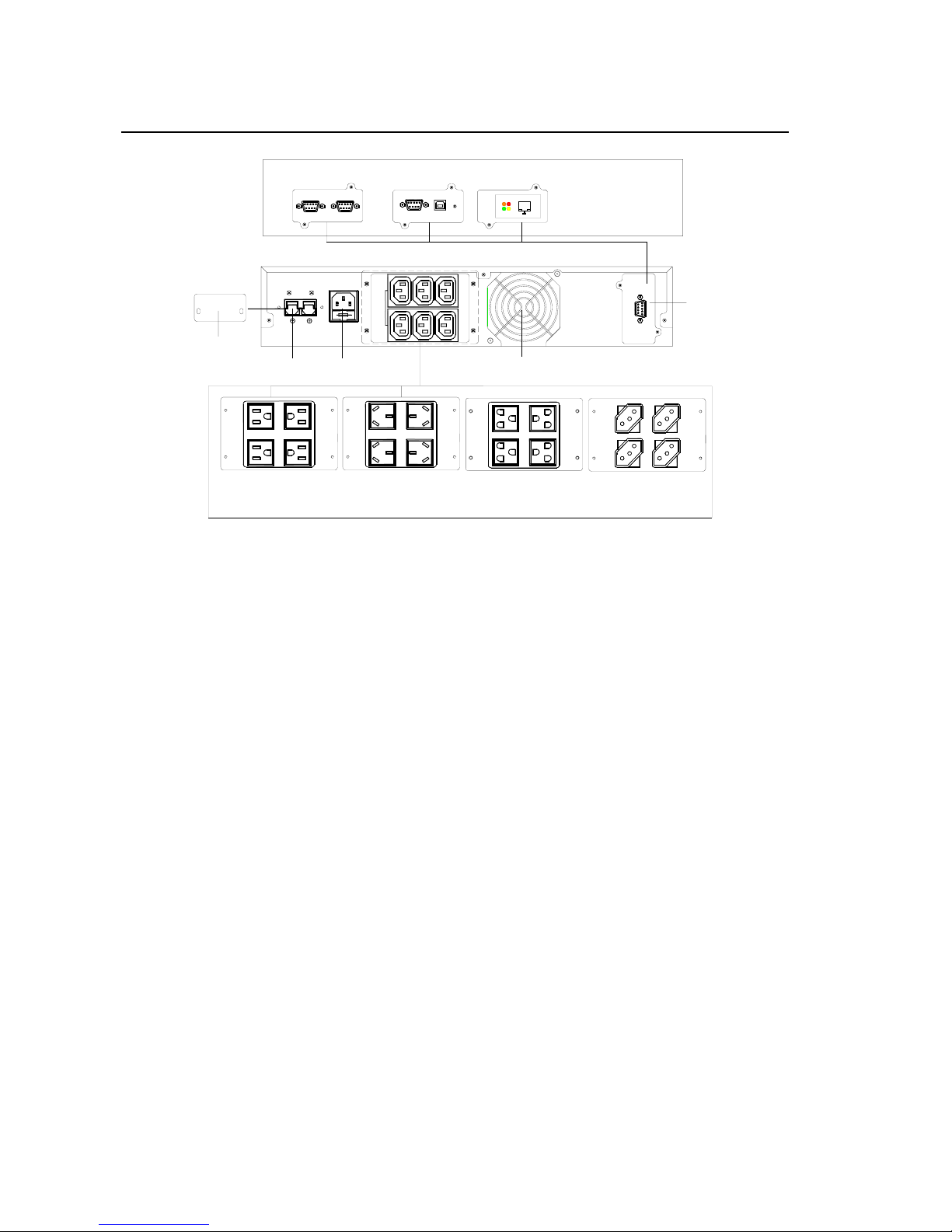
2.1.2 1kVA Rear Panel Structure.............................................................................................5
2.1.3 2kVA & 3kVA rear structure............................................................................................6
2.1.4 1~3kVA series rack mount and tower structure...........................................................8
2.2 Basic Principles...................................................................................................................... 9
2.3 Communication interface....................................................................................................... 9
3 .Equipment Installation .................................................................................................................11
3.1 Site and Environment Requirements .................................................................................. 11
3.1.1 Site Requirements ........................................................................................................11
3.1.2 Environment Requirements.........................................................................................11
3.2 Procedures of Dismantling Cases....................................................................................... 12
3.3 Installation of UPS ................................................................................................................ 12
3.4 Selection of Cable................................................................................................................. 13
3.4.1 Selection of Input Air Switch.......................................................................................13
3.4.2 Selection of Input and Output Power Cord Diameter................................................13
3.5 Cable Connection ................................................................................................................. 14
3.5.1 Rack mount Series Wiring ...........................................................................................14
3.5.2 Inspection of Electric Connection...............................................................................15
4 . Equipment Use and Maintenance.............................................................................................. 17
4.1 Preparations before First Start-up....................................................................................... 17
4.2 UPS Start-up Sequence........................................................................................................ 17
4.3 Daily Start-up and Shutdown............................................................................................... 17
4.4 Battery Daily Maintenance ................................................................................................... 18

-ii-
4.5 Battery Changing...................................................................................................................19
4.6 Maintenance Guide................................................................................................................19
4.6.1 Safety Precaution.........................................................................................................19
4.6.2 Preventive and Regular Maintenance.........................................................................20
4.6.3 FAQ................................................................................................................................20
4.7 Troubleshooting ....................................................................................................................22
4.7.1 Overview .......................................................................................................................22
4.7.2 Troubleshooting ...........................................................................................................22
5 . Packing Transportation and Storage.........................................................................................24
5.1 Packing...................................................................................................................................24
5.2 Transportation........................................................................................................................24
5.3 Storage...................................................................................................................................24
APPENDIX.........................................................................................................................................25

Rack mount Series UPS (1~3kVA) User ‘s Manual
-1-
1.Overview
1.1 Profile
Rack mount (1-3kVA) series UPS are total high frequency, pure online and
intellectualized UPS. They are also ideal power guarantee for file server,
enterprise server, central server, microcomputer, concentrator,
telecommunication system, data center, medical facilities and those who
requiring high quality power protection. They can be widely used in many key
business areas such as post & telecom, finance, network, securities and
railway, etc.
Rack mount (1-3kVA) series UPS are single-phase alternating current input
and output. Each series has two products including standard type and long
backup model.

Rack mount Series UPS (1~3kVA) User ‘s Manual
-2-
1.2 Performance Index
The main performance index of 1-3kVA Series is shown in Table 1-1.
Table 1-1 UPS Main Performance Index
Index Model 1kVA 2kVA 3kVA
Input
Characteristic
Rating voltage (V) In range 160V~290V full load, 50% load even voltage low to 120V
Rating frequency (Hz) 50/60±5%
Input mode Single-phase three-line
Battery voltage (V) 36 72 96
Output Characteristic
Capacity (VA/W) 1000/700 2000/1400 3000/2100
Voltage (V) 220/230/240±2%
Frequency (Hz) 50/60±0.2%(Battery mode)
Waveform Sine wave
Voltage distortion
factor THD < 3% (Linear load)
Power factor 0.7 (Lag)
Switching time (ms) 0
Overload capacity 105%~130% Load, lasting 60 seconds. 135%~150% Load, lasting 30 seconds.≥150% lasting
300 milliseconds
Output mode Sockets Sockets
Other Characteristics
Backup time 5 minutes
(PC LOAD)
Rational
configuration
for long
backup type
5 minutes
(PC LOAD)
Rational
configuration
for long
backup type
5 minutes
(PC LOAD)
Rational
configuration
for long
backup type
Charge recovery time <12 hours (Standard time delay model)
Communication
interface RS232(USB, relay dry connector and SNMP are optional)
Panel display LED or LCD displays operation status of UPS
Warning function Battery low voltage, abnormal power supply, UPS malfunction
Protection function Battery low voltage, overload, short-circuit and over temperature
Frequency noise (dB) < 45
Working temperature 0 ~ 40℃
Relative humidity 0 ~ 95%, No condensation
Size (mm)( W ×D×H) 440×460×88
Weight (kg) 14 7
UPS: 10
Battery pack:
22
12
UPS: 11
Battery pack:
28
13
◆Specifications are subject to change without prior notice.

Rack mount Series UPS (1~3kVA) User ‘s Manual
-3-
1.3 Primary Functions and Characteristics
1.Intelligent RS232 communication function: With RS232 standard data
interface and UPS power management software, realize three
remote-control functions between computer and UPS, computer
supervises UPS operation and electric parameters, and realize
long-distance power on/off function, as well as supporting SNMP
network adaptor (outlaid, connecting UPS through RS232 interface),
which enables UPS to directly become the new member of network.
2.High input power factor: Adopt advanced active PFC technique, which
alleviates load on electric network and represents green power supply of
new generation.
3.High performance-price ratio: Adopts multiple power transfer and high
frequency PWM technique, high efficiency, small size and light weight as
well as improving operational reliability and reducing manufacturing cost,
which lowers the cost of the system design for customers.
4.Perfect protection function: Possess such functions as output
low-voltage protection, battery low-voltage protection, input low-voltage
protection and triple overflowing protection, etc and overcome previous
defects such as high frequency UPS' poor adaptability and weak
resistance to shock for electric network.
5.Low commercial power input voltage: Adopt independent quick detection
technique, even at the lower limit 120V of commercial power, the battery
remains off discharge, thus all energy output are taken from electric
network, ensuring the battery in the state with 100% energy storage,
while at the same time decreasing the battery discharge times and
prolonging its life.
1.4 Precautions
Abide by the following general safety precaution during operation or
maintenance.
1.Please don't remove the cover. This system can only be maintained or
repaired by professional maintenance personnel.

Rack mount Series UPS (1~3kVA) User ‘s Manual
-4-
2.Protective ground terminals should be connected to earth end for sure.
3.High leakage danger! Connect to the ground before connecting UPS.
4.Install this UPS indoors with both temperature and humidity under
control and without dust.
5.The electric power of this UPS has multiple sources. Before maintaining,
cut the alternating current, exterior battery or interior battery's air switch
to isolate the input energy.
6.Even if the AC power supply has been cut off, the danger from battery's
high voltage inside the UPS still exists.
7.If battery circuit has not been isolated from AC input, dangerous voltage
may possibly exists between battery terminal and ground terminal.
8.High voltage endangering personal safety exists in the storage battery
of this UPS. Please pay attention to insulation during installation and
use.
9.Improper handling of acidic battery leads to leakage risk of chemistry
dangerous substance and corrosive liquid.
10.Dripping condensation should be happen if machine was operated under
low-temperature environment. So please install and use machine when
machine was full-dry, or there will has dangerous of electric shock.
Warning: Input and output voltage of this equipment is dangerous high voltage,
which can endanger personal life or safety. Please read carefully this Manual
during installation, operation and before use. Pay attention to various caution
nameplates and caution statements. Professional maintenance personnel
without proper authorization are not allowed to remove off the case cover of
this equipment.

Rack mount Series UPS (1~3kVA) User ‘s Manual
-5-
2 .Structure and Basic Principles
2.1 General Structure
This series UPS 1~3kVA have LED or LCD display for choice. And they could
be used as tower and rack mount type UPS
2.1.1 1~3kVA series Front Panel Structure
1~3kVA series UPS Front Panel have LED or LCD display.
Fig. 2-1 Front Panel
2.1.2 1kVA Rear Panel Structure
1kVA UPS standard type has batteries internal. But for long backup type, the
batteries are external, it has DC input port, please refer to Figure2-2.

Rack mount Series UPS (1~3kVA) User ‘s Manual
-6-
INPUT
DC
FUSE 250V/10A
AC INPUT
AC OU TPUT 10A Max. AC OUTPUT 10A Max.
SIGNAL RS232 RS232 USB
SNMP
NetAgentMini
These communication
interfaces are optional
RS232&dry contact(DB9)
RS232
RS232&USB SNMP
American socket
23 4 5
6
1
RS232
AC
OUTPUT
10A Max.
Chinese socket
AC OUTPUT 10A Max.
Brazilian socket
These input and output modules are optional
AC OUTPUT 10A Max.
New Brazilian socket
Fig 2-2 1kVA rear panel
1kVA rear panel
1. DC input cover
2. DC input port, used for long backup type UPS, please remove the cover No.1 when using.
3. AC input socket
4. AC output socket (optional)
5. Fan
6. Communication interface (optional)
2.1.3 2kVA & 3kVA rear structure
2kVA & 3kVA standard UPS with batteries external which are installed in 2U
height battery cabinet. For long backup UPS, it has DC input port for external
battery pack. UPS rear panel as Figure2-3, Battery cabinet front and rear panel
as Figure 2-4 & 2-5.

Rack mount Series UPS (1~3kVA) User ‘s Manual
-7-
INPUT
DC
SIGNAL RS232 RS232 USB
SNMP
NetAgent Mini
These communication
interfaces are optional
RS232&dry contact(DB9)
RS232
RS232&USB SNMP
5
23 3 4
These input and output modules are optional
FUSE
250V/15A
AC INPUT
PELN AC OUTPUT 10A Max .
FUSE
250V/15A
N
AC INPUT
LPE AC OUTPUT 10A Max.
FUSE
250V/15A
NLPE
AC
OUTPUT
10A Max.
AC OUTPUT
PELN
AC INPUT
1
B
bc
a
RS232
AC
OUTPUT
10A Max.
AC INPUT
PELN
b
a
c
bc
a
bc
a
AC
OUTPUT
10A Max.
AC INPUT
b
a
c
CD
E
FUSE
250V/15A
N
AC INPUT
LPE AC OUTPUT 10A Max.
F
bc
a
AC OUTPUT 10A Max.
N
AC INPUT
LPE
G
bc
a
Fig2-3 2kVA & 3kVA rear panel
2kVA & 3kVA rear panel
1. DC input cover
2. DC input port, used for long backup type UPS, please remove the cover No.1 when using.
3. Fan
4. AC input and output module (optional)
5. Communication interface
Fig 2-4 2U battery cabinet front panel
DC DC
OFFON
GND
1
43
1
22
Fig 2-5 2U battery cabinet rear panel
2U battery cabinet rear instruction
1. DC port cover, remove it when using. Please do not remove if not use, prevent electric

Rack mount Series UPS (1~3kVA) User ‘s Manual
-8-
shock.
2. DC port. One port is used for UPS DC input, another port is used for parallel battery pack.
3. Nut for connecting ground. Connect to ground when using.
4. Breaker
2.1.4 1~3kVA series rack mount and tower structure
1~3kVA series rack mount and tower structure please refer to following
drawing.
UPS rack mount structure
Battery cabinet rack mount structure
UPStowerstructure Batterycabinettowerstructure
Fig 2-6 1~3kVA UPS and battery cabinet rack mount and tower structure

Rack mount Series UPS (1~3kVA) User ‘s Manual
-9-
2.2 Basic Principles
When commercial power is normal, rack mount series UPS input, through PFC,
increases the voltage to ±360V stabilized DC voltage, which supplies DC/AC
inverter and transmits stable 220V AC, while at the same time completing the
charging of the battery. When commercial power is abnormal, the battery
increases the voltage through DC/DC to ± 360V DC voltage and supplies
DC/AC inverter.
UPS principle lock diagram is shown in Fig. 2-7. DC/AC inverter adopts
half-bridge structure, while DC/DC voltage increase adopts push-pull or
BOOST circuit. PFC is active power-factor correction circuit controlled by
UC3854, while CHARGER is complete isolation type charger.
CHARGE
PFC AC/DC SW
BATTERY
DC/DC
DC/AC LOAD
220Vac
Fig. 2-7 UPS Basic Principle Block Diagram
2.3 Communication interface
This series UPS has four communication interfaces for choice. Among which
RS232 & dry contact port instruction as below:
Corresponding relations of pins for the RS232 serial ports of this series UPS
and those of general PC as Table 2-1.
162738495
Fig. 2-8 RS232 pins definitions

Rack mount Series UPS (1~3kVA) User ‘s Manual
-10-
Table 2-1 Corresponding relations of pins for the RS232 serial ports of this series UPS
and those of general PC:
Communication RS232 Interface for UPS General RS232 Interface
9 (3) 2 (Receive)
6 (2) 3 (Deliver)
7 (5) 5 (Ground)
Dry contact communication port pins definitions as Figure 2-9, signal definitions
as Table 2-2.
162738495
Fig 2-9 Dry contact pins definition
Table 2-2 UPS Dry contact communication signal definitions
Status Dry contact signal description
Battery normal P1-P2 close, P2 –P3 open
Battery fault P1-P2 open, P2 –P3 close
Main normal P4-P5 close, P5 –P6 open
Main fault P4-P5 open, P5 –P6 close
UPS normal P7-P8 close, P8 –P9 open
UPS fault P7-P8 open, P8 –P9 close
Note: The normal status indicates that relay pulls, and the fault status indicates
that relay releases.

Rack mount Series UPS (1~3kVA) User ‘s Manual
-11-
3 .Equipment Installation(删除上面一空白页)
3.1 Site and Environment Requirements
Before UPS installation, the site and environment of equipment room should
meet the essential conditions for safe and normal operation of equipment as
defined in this section. If the customer’s site conditions are not accord with the
minimum requirement of safe equipment operation, the customer should make
corresponding changes to the site conditions, and install the equipment only
after meeting the conditions of safe and normal equipment operation.
3.1.1 Site Requirements
The site conditions should accord with the essential conditions of safe and
normal equipment operation as stated in this section.
1.The equipment room must be equipped with applicable and effective fire
apparatus;
2.The commercial power, which supplies power for UPS, should be equipped
with dedicated air switch or utility socket;
3.Strictly prohibit storing dangerous things, such as inflammable things,
explosive things in the equipment room;
4.Before equipment installation, the ground wire should be prepared. The
voltage of neutral wire and ground wire of commercial power cannot
exceed 5V;
5.The civil engineering construction of the equipment room should be
completed totally, and the floor should be sclerotic. The site must be tidy
and dry without dust.
3.1.2 Environment Requirements
Ambient temperature: 0℃~+40℃;
Relative humidity: 0%RH~95%RH, no condensation;
Cooling mode: air-cooling;
Verticality: no shock with orthogonal rake not exceeding 5º.

Rack mount Series UPS (1~3kVA) User ‘s Manual
-12-
3.2 Procedures of Dismantling Cases
When installing the equipment, the packing should be removed after carrying
the equipment to the installation site. The packing of UPS equipment and
fittings (battery, etc.) should be wooden case and carton. Check the UPS
equipment and fittings against the shipping list.
If the equipment or fittings are damaged during transportation or the equipment
and fittings are not accord with the ordering contract, make site record in time
and immediately contact the local office or distributors.
3.3 Installation of UPS
Because the main unit size of rack mount series standard time-delay model
and long time-delay model is small, the UPS can be placed on the flat surface
directly without other fixing or installation. For convenient operation,
maintenance and heat emission of the equipment, there shall be at least
30cm~50cm room space reserved around the machine frame and 50cm above
the upper machine frame. The vent fan shall be installed beside the battery.
Keep good interior ventilation. The service life of the battery is the longest
when the battery is used under normal temperature (20℃). Recommend to
install air-conditioning equipment in equipment rooms with allowed conditions.
Refer to Fig. 3-1 for the precautions of UPS installation and use.
Fig. 3-1 Precautions of UPS Installation and Use

Rack mount Series UPS (1~3kVA) User ‘s Manual
-13-
1.Place UPS on flat floor (avoid oblique and ragged floor).
2.Keep good ventilation, the distance of the back and side to the wall should
be above 30cm~50cm, to facilitate heat emission.
3.Avoid placing it in the location with sunshine, rain and dampness.
4.Never place it in the location with corrosive air.
5.Do not place articles on or around the UPS, to prevent the vent hole from
being blocked. No person is allowed to sit on it.
3.4 Selection of Cable
3.4.1 Selection of Input Air Switch
Before the input coil in of the equipment, install an air switch or a distribution
box compliant with the power and capability of the equipment, to isolate it with
commercial power. Consider especially the charge power and the current
shock, the input air switch can be higher than 1.5-2 times most current of UPS
input, which is without leakage protection in order to avoid error action. The
distribution box should be better to be manufactured by professional company.
Please refer to Table 3-1.
Table 3-1 Recommended Sectional input air switch
1kVA 2kVA 3kVA
Most
Current
(A)
Recommended
Air switch
(A)
Most
Current
(A)
Recommended
Air switch
(A)
Most
Current
(A)
Recommended
Air switch
(A)
AC
Input
6 10 12 20 18 32
DC
Input
26 50 26 32 30 50
3.4.2 Selection of Input and Output Power Cord Diameter
For the selection of conducting wire sectional area for UPS AC input and output
cable and battery cable, please refer to Table 3-2 for corresponding
recommended values, and choose values upwards.

Rack mount Series UPS (1~3kVA) User ‘s Manual
-14-
Table 3-2 Recommended Sectional Flow of Cable Sectional Area of UPS
Ampacity
(A)
Sectional Area (mm2)
1 1.5 2.5 4 6 10 16 25
Rubber
(25°C) 8 12 20 28 42 70 96 125
Plastic
(25°C) 6 9 15 20 30 50 64 100
3.5 Cable Connection
To connect UPS cable only after confirming that all air switches on UPS are in
disconnection condition, and the equipment is properly installed.
3.5.1 Rack mount Series Wiring
1kVA standard UPS with battery internal and long backup type UPS wires
connection as Figure 3-2. As for the standard UPS with battery internal, it
doesn’t need the operation of step 1&step 2 and remove the DC input cover.
INPUT
DC
FUSE 250V/10A
AC INPUT
2.DC
Input
DC
Source
Socket output
to load
Socket output
to load
Socket output
to load
Socket output
to load
Share
alike
!
Share
alike
!
Commercial
power input
1.Take
off cover
Commercial
power socket
Communite with
computers or moniters
Figure 3-2 1kVA wires connection
Caution:
Step 1. Mains socket should be installed near the equipment and should be
easy to touch.
Step 2. For long backup type UPS, it needs to connect battery input wire, that’s
to connect the battery cable to the rear panel socket of UPS. The

Rack mount Series UPS (1~3kVA) User ‘s Manual
-15-
Battery cabinet installation and battery cabinet cable connections
please refer to the installation manual.
Step 3. For the long backup type UPS, the battery connecting line could be
connected with UPS only after the UPS with mains input
Picture shows only one of four modes of communication interface.
2kVA & 3kVA wires connection as Figure 3-3 showed:
INPUT
DC
FUSE
250V/15A
N
AC INPUT
LPE AC OUTPUT 10A Max.
LNPE
DC DC
OFFON
GND
RS232
1.Take
off cover
3. DC
Source
2.DC
Input Socket output
to load
Socket output to load
Socket output
to load
Share
alike
!
Share
alike
!
220V AC Power System
Connecting to the rack
Communite with
computers or moniters
Figure 3-3 2kVA & 3kVA wire connection
Cautions:
Step 1. Mains socket should be installed near the equipment and should be
easy to touch.
Step 2. For long backup type UPS, it needs to connect battery input wire, that’s
to connect the the battery cable to the rear panel socket of UPS. The
Battery cabinet installation and battery cabinet cable connections
please refer to the installation manual.
Step 3. For the long backup type UPS, the battery connecting line could be
connected with UPS only after the UPS with mains input
Note: Picture shows only one of four modes of communication interface, the
customer can choose other communication interfaces when place order.
3.5.2 Inspection of Electric Connection
1.Inspection of AC input wire: Whether the AC wire color spectrum is

Rack mount Series UPS (1~3kVA) User ‘s Manual
-16-
normative. Whether the wire diameter of AC input cable is suitable.
Whether control switch is connected outside. Whether the connection of
line wires (L), neutral wire (N) and ground wire (PE) is correct. Whether
the connection of AC input wire is firm.
2.Inspection of AC output wire: Whether the AC output wire color
spectrum is normative. Whether the wire size of AC output cable is
suitable. Whether switch in the control switch outside. Whether the
connection of line wires (L), neutral wire (N) and ground wire (PE) is
correct. Whether the connection of AC output wire is firm.
3.Inspection of ground wire: Whether the ground wire of UPS is connected
to the ground line bank of the equipment room. Whether the connection
of ground wire is reliable.
4.The inspection of the voltage difference between neutral wire and
ground wire: the voltage difference should be less than 5Vac.
5.If the customer adopts the configuration of long time-delay model,
examine whether the battery cable connection of main unit box and
battery box is correct and reliable.
6.If the UPS is installed with remote monitoring equipment, examine
whether the connection of relevant RS232 serial port is correct.
7.Examine whether the wiring is in order, whether the cable binding
accord with the technical criterion.
8.Examine whether the installation and wiring are in favor of the future
system modification, expansion and maintenance.
Table of contents