JBJ Lighting Varyscan 4 1200 HMI User manual

JB-lighting Lichtanlagentechnik GmbH
Sallersteigweg 15 D-89134 Blaustein-Wippingen
Telefon++49(0)7304-9617-0
Telefax ++49(0)7304-9617-99
http://www.jb-lighting.de
english
Bedienungsanleitung
User Manual

2
Varyscan®4 1200 HMI
Illustration of VS 4 1200HMI..........................................................................................................................3
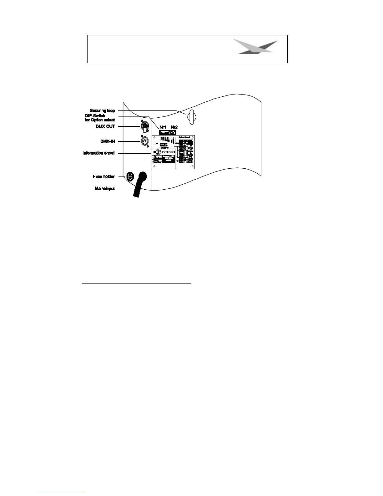
Back view and position of operating sections...................................................................................4
Unpacking of the Varyscan®Equipment.....................................................................................................4
Put in/ Exchange of the Bulb.........................................................................................................................5
Starting the Equipment..................................................................................................................................5
1. Hang up of Varyscan®........................................................................................................................5
2. Adjustment of Varyscan®...................................................................................................................5
3. Cabling of Varyscan®..........................................................................................................................5
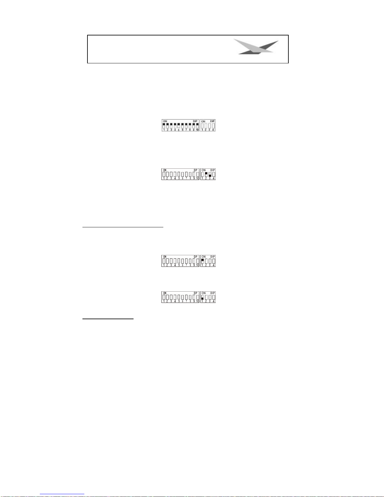
4. Adjustment at DIP-switches .............................................................................................................5
Initialisation Mode...................................................................................................................................6
Test Mode.................................................................................................................................................6
Adjustments at DIP-Switch No.2..........................................................................................................6
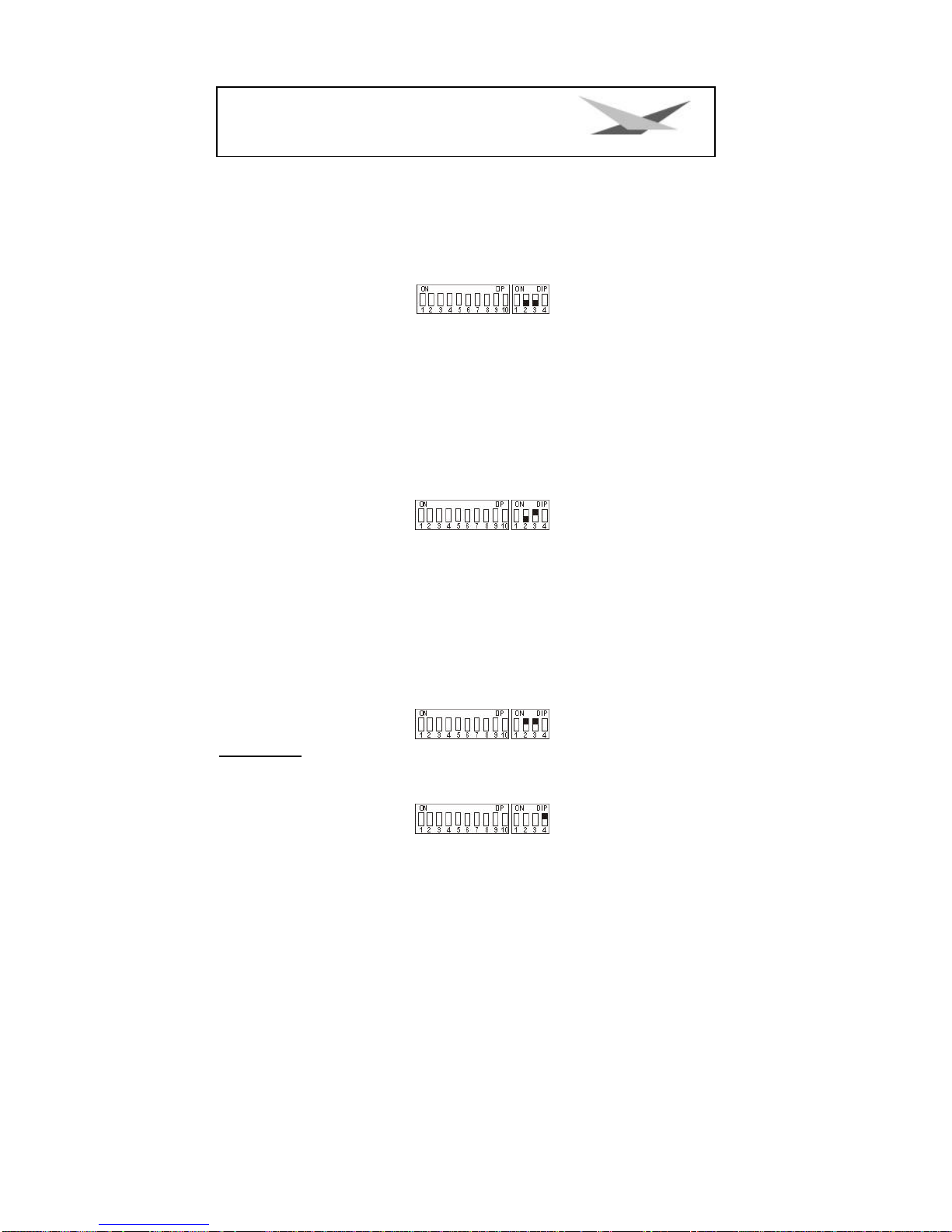
1. JB lighting 8 channel drive mode....................................................................................................6
2. 6 channel drive mode (Clay Paky -Goldenscan 3 compatible).................................................7
3. JB-lighting 6 channel drive mode....................................................................................................7
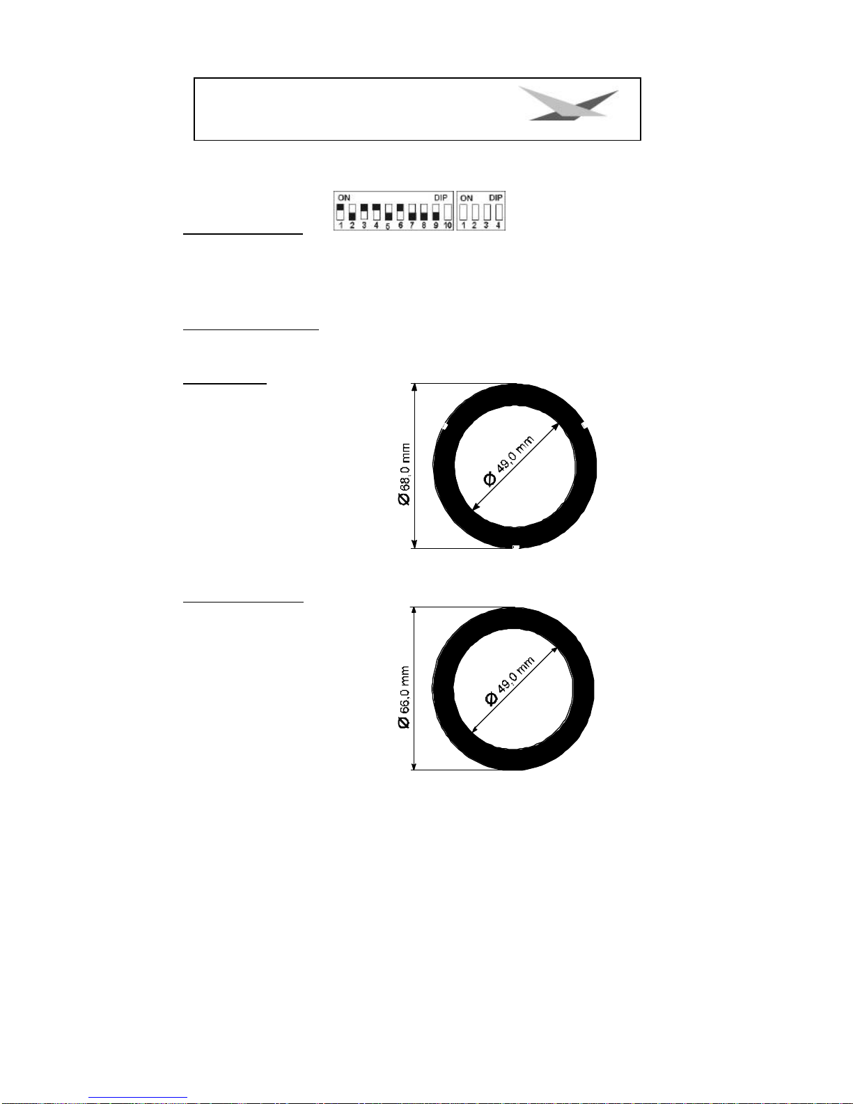
Definition of DIP-switch positions for defined DMX-addresses.............................................................9
Changing of gobos......................................................................................................................................10
GOBO measurements................................................................................................................................10
B Service instructions..................................................................................................................................11
Adjustment of the mirror stop............................................................................................................11
Adjustment of the motor brake..........................................................................................................11
Regular Maintenance Performances...............................................................................................12
1. Cleaning of all optical parts...........................................................................................................12
2. Cleaning of ventilation............................................................................................................................12
3. Oiling of rotating gobos ..................................................................................................................13
General Information about DMX512 record............................................................................................13
Occupation of channels for Varyscan®4 1200 HMI ...............................................................................13
Occupation DMX-In / DMX-Out...................................................................................................................18
Technical data ..............................................................................................................................................18
Change of Eprom/ Software Update ........................................................................................................19
Plan of current circuits for Varyscan®4 1200HMI...................................................................................20
Occupation of connectors and Jumper....................................................................................................21
List of parts or electronic board of Varyscan®4 1200 HMI ...................................................................21
Plan of electronic parts for electronic board of Varyscan®4 1200 HMI..............................................25

3
Varyscan®4 1200 HMI
Illustration of VS 4 1200HMI

4
Varyscan®4 1200 HMI
Back view and position of operating sections
Occupation of DMX-sockets
DMX-in DMX-out
Pin No. signal Colour of wire Pin No. Signal Colour of wire
1 Ground black 1 Ground black
2 DMX -white 2 DMX -white
3 DMX + red 3 DMX + red
4 free 4 not connected
5 +5V green/black 5 not connected
Unpacking of the Varyscan®Equipment
The box contains:
Varyscan®1200 HMI
operating instructions
Check, if the delivery contains all parts.
Should you notice a damage through transportation, please inform immediately the carriers respectively your
dealer. Also in case of noticing missing parts.

5
Varyscan®4 1200 HMI
Put in/ Exchange of the Bulb
Warning: Before opening pull out mains plug!
Loosen the screws at the lid of your Varyscan®with a suitable screw-driver and lift the lid (label Varyscan®4
1200 HMI). You can see the bulb holder in the back third of your
Varyscan®(see outline page 4). Now detach nuts No.1 and No.2 and
remove the bulb from it's holder. Put the new HMI bulb into the holder
and tighten nuts No.1 and No.2 by hand. The point on the glass of the
bulb should on no account point to the concave mirror, respectively to
the lenses (outline page 4), it should point to the base sheet or to the lid.
Take care that the bulb is tightened in the holder.
Warning: Never touch the glass of bulb of the 1200 HMI bulb itself!
An adjustment of the bulb is not necessary.
Starting the Equipment
1. Hang up of Varyscan®
To scoop the optimal functioning of your Varyscan®, you should hang up the spots as high as possible.
2. Adjustment of Varyscan®
All spots should hang in the same angle, i.e. the imagined angle between perpendicular and Varyscan®should
be the same among all Varyscans®
3. Cabling of Varyscan®
Power supply:
A specialist should attach a plug to the open end of the connecting cable, or have the cable connected to 230
volt 50 hertz.
DMX-cabling:
Connect the output of your DMX-controller with the first Varyscan®(controller DMX-out; Varyscan®DMX-in)with
the aid of a 5pole XLR-cabel. Now establish the connection between the Varyscans®with the aid of further
5pole XLR-cables. Make sure that in DMX-out of the last Varyscan®there is a resistor (XLR-plug with a resistance
of 100 Ohm between pin 2 and pin 3) plugged into.
4. Adjustment at DIP-switches
At DIP-switch No.1 and No.2 you have the following possibilities of adjustment:
?initialisation mode
?test mode
?infinitely variable colour changing

6
Varyscan®4 1200 HMI
?optional channels of Varyscan®
?reset on DMX
?DMX-address
Initialisation Mode
This mode serves for adjustment and basic initialisation of the Varyscan®(carrying-out by producer).
Test Mode
To see the variety of functions of your Varyscan®easily, start the test mode by turning switch 3 off and switch 2
on at DIP-switch No.2. Now plug in your scanner and you will largely see it's functions.
Adjustments at DIP-Switch No.2
Before adjusting DMX-addresses, you have to choose a certain drive mode and then make the right choice of
addresses.
At DIP-switch No.2 you find 4 switches for choosing the following functions.
Infinitely Variable Colour Changing: DIP-switch No.2 switch 1
i.e. the moment this function is turned on, every DMX-factor between 0 and 128 corresponds to an adjustment
of the colour wheel. You can produce not only half colours but 1/3-2/3 colours or 1/4-3/4 colours etc. To
choose this function, turn switch 1 at DIP-switch No.2 on.
Is switch 1 on position off, you get only full colours, respectively half colours.
Optional Drive Modes: DIP-switch No.2 switch 2 and 3
You have 3 DMX-channel formats to your disposal, which are explained precisely in the following text.
1. JB lighting 8 channel drive mode
channel 1 x-axis

7
Varyscan®4 1200 HMI
channel 2 y-axis
channel 3 gobo
channel 4 colour
channel 5 shutter/dimmer
channel 6 iris
channel 7 rotating gobos; positioning and rotation
channel 8 effect wheel
DIP-switch position: DIP-switch No.2 switch 2 and 3 off
2. 6 channel drive mode (Clay Paky -Goldenscan 3 compatible)
channel 1 iris and gobo rotation
channel 2 colour
channel 3 gobo and effect wheel
channel 4 dimmer/shutter
channel 5 x-axis
channel 6 y-axis
DIP-switch position: DIP-switch No.2 switch 2 off, switch 3 on
3. JB-lighting 6 channel drive mode
channel 1 x-motor
channel 2 y-motor
channel 3 gobo
channel 4 colour
channel 5 dimmer/shutter
channel 6 iris/gobo rotation
DIP-switch position: DIP-switch No.2 switch 2 and 3 on
Reset on DMX:DIP-switch No.2 switch 4
If you would like to reset your Varyscan®from your DMX-desk, turn switch 4 on at DIP-switch No.2. Now you have
the possibility to reset your Varyscan®, if you transmit DMX-factor 255 via gobo channel.
If switch 4 at DIP-switch No.2 is turned off, reset on DMX is not possible.

8
Varyscan®4 1200 HMI
Adjustment of DMX-addresses:DIP-switch No.1 switch 1-9
Depending on the optional drive mode, you have to adjust DMX-addresses as follows. The addressing works by
a binary numeral system and in 6 channel drive mode it has to follow in six steps.
Varyscan®Nr. DMX address Dip switch setting
11
27
313
419
525
631
737
843
949
10 55
11 61
12 67
In 8 channel drive mode addresses have to be adjusted in 8 steps.
Varyscan®Nr. DMX address Dip switch setting
11

9
Varyscan®4 1200 HMI
29
317
425
Varyscan®Nr. DMX address Dip switch setting
533
641
749
857
965
10 73
11 81
12 89
Definition of DIP-switch positions for defined DMX-addresses
Every single DIP-switch responds to the above designated figures. If you would like to adjust a defined DMX-
address, you have to add up the single figures to get it.
For example: DMX-address "45"
32 + 8 + 4 + 1 = 45
SW6 SW4 SW3 SW1
on on on on

10
Varyscan®4 1200 HMI
All remaining DIP-switches SW9 SW8 SW7 SW5 SW2 stay in position "OFF".
Changing of gobos
Open the lid with the label Varyscan®4 1200 HMI, by screwing off the six screws. Now you are
able to press the gobos at the gobo wheel out of their holder and then put in other gobos. Take
care that the gobo engages exactly with it's slits in the holder. If the gobo is put in correctly, it
moves easily inside the holder. Now you can close the lid.
GOBO measurements
With your Varyscan®, you have the chance of using two different gobo sizes.
1. Gobos JB-size
Outside diameter: 68,0 mm
Use diameter: 49,0 mm
2. Standard size (M-size)
Outside diameter: 66,0 mm
Use diameter: 49,0 mm

11
Varyscan®4 1200 HMI
B Service instructions
Repair of defects
Defect Reparation
The appliance does not work at all (you can
not hear any noise from the ventilator) Exchange 16 Ampere fuse of the appliance
The bulb of the appliance does not shine, but
electronics are working, i.e. motors are working
1. The bulb is defect and you have to change
it
2. The temperature switch of the appliance is
released. Plug out your Varyscan®and after
approximately 15 minutes plug it in again.
Check now, if both ventilators are working and
if they are clean. If one of the ventilators is de-
fect, have it exchanged by a specialist or the
p
roducer. If the scan turns off again and again,
please contact your dealer.
DMX-input does not work Control DIP-switch position
Adjustment of the mirror stop
To adjust the mirror of your Varyscan®1200 HMI, proceed as follows:
Adjust the initialisation mode at DIP-switch No.1 (DIP-switch position see page 7) and start your
Varyscan®. Now wait until the initialisation of the scan is ran through and all motors stopped.
Then loosen screw No.1 Now turn the holder
for the y-motor towards the stop up to a
distance of 0,5 mm. Tighten screw No.1 now.
During tightening the screw pay attention to the
correct adjustment of the motor brake (see
sketch below). Loosen screw No.2 and turn
the y-motor towards the holder for the y-motor
and adjust hereby a distance of 0,5 mm
between the stop and the holder for the y-
motor.
Adjustment of the motor brake
The motor brake is similar at each of the
stepper motors of the scan. There are three
special parts (part no. 2,3 and 4) which must be installed in the following succession:

12
Varyscan®4 1200 HMI
Part no. 1. motor
Part no. 2. Tellerfedern
Part no. 3. Stahllaserteil
Part no. 4. Kunststoffscheibe
Part no. 5. zu montierendes Teil
Part no. 5 has to be pushed on the axis of the stepper motor until
the parts no. 2 can not be compressed anymore. After remove the
part no. 5 about 0,5 mm and turn the fastening screws. The
"motor-brake" is now optimum adjusted .
Regular Maintenance Performances
Warning: Before open the appliance pull out mains plug!
Open the casing by turning out the screws at the top of the Varyscan®.
To be able to take out the slide-in modules of your Varyscan®, you have to screw off two screws
of silver at the side-piece, up to the mark of the slide-in modules. Now you are able to take out
the slide-in modules (sketch page 4).
Attention:Do not forget to lock in the slide-in modules after having completed
your maintenance performances, by screwing in the screws of silver
carefully!
1. Cleaning of all optical parts
You should clean the optical parts of your Varyscan®periodically to restore maximum brightness
of the scan. After having opened the casing as explained above, take out the effect wheel slide-in
(see sketch page 4) and put it on anunderlay in front of you. Take a fuzz-free rag and a detergent
for windows and clean the effect filters on the effect wheel.
Subsequently clean both lenses (sketch page 4). In order to clean the lens easily, loosen the
screw which fixes the lens and remove the lens. Now it is easy to clean from the outside and the
inside. Take out the colour wheel slide-in in order to clean the dichroitic filters. Put in the lens,
the effect wheel slide-in and the colour wheel slide-in. Do not forget to tighten the screw which
fixes the lens.
2. Cleaning of ventilation
You should check regularly the function of the ventilators. Above all take care that ventilation
inlets and the interior of the Varyscan* are free from fuzzes and other dust. Open both lids of your
Varyscan®, by screwing off the screws from the lids. Now clean your Varyscan* carefully with a
vacuum cleaner. Now screw down the lid. Take care that you use the sheet metal screws for
closing the smaller lid.

13
Varyscan®4 1200 HMI
Attention: Take care that you do not twist or damage any parts while cleaning
your scan!
3. Oiling of rotating gobos
Procure a syringe with a thin needle, customary in trade (grind off the tip, so it will be blunt -no
risk of injury!!), and fill it with our special oil. On no account use another kind of oil, because our
oil is a special mixture. Now syringe the oil between the brass gear wheels and the brass plate
and turn the rotating gobos by hand.
Attention: Do not use too much oil!
General Information about DMX512 record
The DMX512 record is devided in 512 addresses. You have 512 addresses for your disposal. To
be able to connect different appliances with a DMX-controller, it is necessary to determine the
number of DMX-channels for every appliance. The occupation of channels of a scan could be
like that for example:
channel 1 x-movement
channel 2 y-movement
channel 3 gobo/effect wheel
channel 4 colour
channel 5 shutter/dimmer
channel 6 iris/gobo positioning/gobo rotation
In order that not every connected DMX-appliance performs same functions, the appliances are
addressed in series; i.e. for the first appliance the first 6 addresses are used (be right for an
appliance with six channels), for the second one (appliance with six channels) the next 6
addresses of all the DMX-addresses are used (see for example Varyscan®page 48).
Occupation of channels for Varyscan®4 1200 HMI
1. JB lighting 8 channels
Channel 1 X-movement
Channel 2 Y-movment
Channel 3 gobo
Channel 4 shutter / dimmer
Channel 5 color
Channel 6 Iris
Channel 7 rotating gobos (positioning and rotating)
Channel 8 effect wheel

14
Varyscan®4 1200 HMI
channel 1 = x (pan) 170°
channel 2 = y (tilt) 90°
channel 3 = gobo
gobo 0 (Beam) DMX 000-031
gobo 1 DMX 032-063
gobo 2 DMX 064-095
gobo 3 DMX 096-127
gobo 4 DMX 128-255
if at DIP-switch No.2 switch 4 is "ON"
gobo 4 DMX 128 -254
Reset DMX 255
channel 4 = colour
colour 0 (white) DMX 000-007
colour 1 DMX 008-015
colour 2 DMX 016-023
colour 3 DMX 024-031
colour 4 DMX 032-039
colour 5 DMX 040-047
colour 6 DMX 048-055
colour 7 DMX 056-063
colour 8 DMX 064-071
colour 9 DMX 072-079
colour 10 DMX 080-087
colour 11 DMX 088-095
colour 12 DMX 096-103
colour 13 DMX 104-111
colour 14 DMX 112-119
colour 15 DMX 120-127
colour wheel rotation speed 1 (slow) DMX 128-
colour wheel rotation speed 7 (fast) DMX 255
channel 5 = dimmer / shutter
dimmer shutter closed --> blackout (BO) DMX 0
dimmer: you can perceive some light DMX 19
dimmer DMX 20 -127
dimmer completelyopen DMX 128-137
shutter immediatelly closed DMX 138-139
shutter sequence 1 flash/sec upto 10 flashes/sec DMX 140-243
shutter open DMX 244-255
channel 6 = iris
iris (linear) DMX 000-255
channel 7 = rotating gobos (positioning and
rotation
0° DMX 000
180° DMX 063
360° DMX 126
540° DMX 191
rotation left (fast) DMX 192

15
Varyscan®4 1200 HMI
rotation left (slow) DMX 222
rotation stop DMX 223-224
rotation right (slow) DMX 225
rotation right (fast) DMX 255
channel 8 = effect wheel
open DMX 000-031
artificial light filter DMX 032-063
daylight filter DMX 064-095
prism DMX 096-127
floodfilter DMX 128-159
infinitely variable from flood to open DMX 160-255
2. 6 channels (Clay Paky Goldenscan 3 compatible)
channel 1 iris and gobo rotation
channel 2 colour
channel 3 gobo and effect wheel
channel 4
dimmer / shutter
channel 5 X-axis
channel 6
Y-axis
channel 1 = iris and gobo rotation
iris cl osed / gobo first position DMX 0
iris open / gobo first position DMX -64
second gobo position DMX 65
third gobo position DMX 66
..........
locked into position 360° DMX 191
locked into position 540° DMX 191
rotation left highest speed DMX 192
rotation left lowest speed DMX 222
rotation stop DMX 223 -224
rotation right lowest speed DMX 225
rotation right highest speed DMX 255
channel 2 = colour
colour 0 (white) DMX 000 -007
colour 1 DMX 008 -015
colour 2 DMX 016 -023
colour 3 DMX 024 -031
colour 4 DMX 032 -039
colour 5 DMX 040 -047
colour 6 DMX 048 -055
colour 7 DMX 056 -063
colour 8 DMX 064 -071
colour 9 DMX 072 -079
colour 10 DMX 080 -087
colour 11 DMX 088 -095

16
Varyscan®4 1200 HMI
colour 12 DMX 096 -103
colour 13 DMX 104 -111
colour 14 DMX 112 -119
colour 15 DMX 120 -127
colour wheel rotation speed (slow) DMX 128 -
colour wheel rotation speed (fast) DMX 255
channel 3 = gobo and effect wheel
white DMX 0-9
artificial light filter DMX 10 -19
daylight filter DMX 20 -29
prism DMX 30 -39
floodfilter DMX 40 -51
gobo 1 white DMX 52 -64
gobo 1 artificial light filter DMX 65 -77
gobo 1 daylight filter DMX 78 -90
gobo 1 prism DMX 91 -103
gobo 2 white DMX 104 -116
gobo 2 artificial light filter DMX 117 -129
gobo 2 daylight filter DMX 130 -142
gobo 2 prism DMX 143 -155
gobo 3 white DMX 156 -168
gobo 3 artificial light filter DMX 169 -181
gobo 3 daylight filter DMX 182 -194
gobo 3 prism DMX 195 -207
gobo 4 white DMX 208 -220
gobo 4 artificial light filter DMX 221 -233
gobo 4 daylight filter DMX 234 -246
gobo 4 prism DMX 247 -255
if at DIP-switch No. 2 switch is "ON"
GOBO 4 prism DMX 247 -254
Reset DMX 255
channel 4 = dimmer / shutter
dimmer shutter closed --> blackout (BO) DMX 0
dimmer: you can perceive some light DMX 19
dimmerDMX 20 -127
dimmer completely open DMX 128 -137
shutter immediatelly closed DMX 138 -139
shutter sequence 1 flash/sec upto 10 flashes/sec DMX 140 -243
shutter open DMX 244 -255
channel 5 = x (pan) 170°
channel 6 = y (tilt) 90°
3. JBlighting 6 channels
channel 1 X-axis
channel 2 Y-axis
channel 3 gobo and effect wheel
channel 4 colour

17
Varyscan®4 1200 HMI
channel 5 simmer shutter
channel 6 iris and goborotation
channel 1 = x (pan) 170°
channel 2 = y (tilt) 90°
channel 3 = gobo and effectwheel
white DMX 0-9
artificial light filter DMX 10 -19
daylight filter DMX 20 -29
prism DMX 30 -39
floodfilter DMX 40 -51
gobo 1 white DMX 52 -64
gobo 1 artificial light filter DMX 65 -77
gobo 1 daylight filter DMX 78 -90
gobo 1 prism DMX 91 -103
gobo 2 white DMX 104 -116
gobo 2 artificial light filter DMX 117 -129
gobo 2 daylight filter DMX 130 -142
gobo 2 prism DMX 143 -155
gobo 3 white DMX 156 -168
gobo 3 artificial light filter DMX 169 -181
gobo 3 daylight filter DMX 182 -194
gobo 3 prism DMX 195 -207
gobo 4 white DMX 208 -220
gobo 4 artificial light filter DMX 221 -233
gobo 4 daylight filter DMX 234 -246
gobo 4 prism DMX 247 -255
if at DIP-switch No. 2 switch 4 is "ON"
gobo 4 prism DMX 247 -254
Reset DMX 255
channel 4 = colour
colour 0 (white) DMX 000 -007
colour 1 DMX 008 -015
colour 2 DMX 016 -023
colour 3 DMX 024 -031
colour 4 DMX 032 -039
colour 5 DMX 040 -047
colour 6 DMX 048 -055
colour 7 DMX 056 -063
colour 8 DMX 064 -071
colour 9DMX 072 -079
colour 10 DMX 080 -087
colour 11 DMX 088 -095
colour 12 DMX 096 -103
colour 13 DMX 104 -111
colour 14 DMX 112 -119
colour 15 DMX 120 -127
colour wheel rotation speed (slow) DMX 128 -

18
Varyscan®4 1200 HMI
colour wheel rotation speed (fast) DMX 255
channel 5 = dimmer / shutter
dimmer shutter closed --> blackout (BO) DMX 0
dimmer: you can perceive some light DMX 19
dimmer DMX 20 -127
dimmer completely open DMX 128 -137
shutter immediatelly closed DMX 138 -139
shutter sequence 1 flash/sec upto 10 flashes/sec DMX 140 -243
shutter open DMX 244 -255
channel 6 = iris and gobo rotation
iris closed / gobo first position DMX 0
iris open / gobo first position DMX -64
second gobo position DMX 65
third gobo position DMX 66
..........
locked into position 360° DMX 191
locked into position 540° DMX 191
rotation left highest speed DMX 192
rotation left lowest speed DMX 222
rotation stop DMX 223 -224
rotation right slow DMX 225
rotation right fast DMX 255
Occupation DMX-In / DMX-Out
DMX-IN DMX-OUT
Pin1: ground black Pin1: ground black
Pin2: DMX-beige Pin2: DMX-beige
Pin3: DMX+ red Pin3: DMX+ red
Pin4: free Pin4: free
Pin5: + 5V green Pin5: free
Technical data
Measurements: hight 100cm
width 34cm
depth 24cm
Weight: 36 kg
Power consumption: ca. 1725W
Mains Voltage: 230V 50Hz 7,5A
Bulb :Osram 1200 HMI
Fuse: 16 ampere inert

19
Varyscan®4 1200 HMI
Change of Eprom/ Software Update
To change the Eprom proceed as follows:
Remove the cover sheet for the electronic board below the mirror by taking out the 4 screws (see sketch page
36). By comparing the electronic board with the plan of electronic parts you can see the Eprom at the right side
(IC U2). Carefully lift out the used Eprom from the holder and change it for a new one.
Attention: Pay attention to the polarity of the Eprom!
(The inlet of the Eprom has to point to the same direction as the inlet of the IC-holder.)
Close the lid and fix it with screws. Plug in your Varyscan®and please test all functions.

20
Varyscan®4 1200 HMI
Plan of current circuits for Varyscan®4 1200HMI
Table of contents