· 8 ·
REF. 53688
BEDIENUNGSANLEITUNG
DE
PRODUKTBESCHREIBUNG
Der Starter ist zum Starten von Autos, Motorbooten und an-
deren Fahrzeugen, wenn es unter normalen Bedingungen
unmöglich ist, Ihren Motor zu starten, ohne fremde Hilfe vor-
gesehen. Das Gerät ist mit einer 12/24 V-Stromversorgung,
die in Notfallsituationen eingesetzt werden kann, sowie mit
LEDs zur Signalisierung über den internen Batteriestatus
ausgerüstet. Dieser Starter kann Geräte mit einer Span-
nung von 12 V DC über eine spezielle Steckdose mit Strom
versorgen sowie mittels des externen Ladegeräts durch den
Anschluss an die Ladesteckdose aufgeladen werden. Zum
Schutz der Batterie ist ein automatisches Überlastschut-
zsystem vorgesehen.
SICHERHEITSHINWEISE
WARNUNG! Lesen Sie alle Warn- und Sicherheits-
hinweise durch. Andernfalls kann es zu Stromschlägen,
Bränden und/oder schweren Verletzungen kommen.
• Stellen Sie sicher, dass der Arbeitsbereich sauber und
gut beleuchtet ist.
• Lassen Sie Kinder und unbefugte Personen nicht in der
Nähe des Arbeitsbereichs stehen.
• Betreiben Sie das Gerät nicht, wenn Sie müde sind
oder unter Alkohol -, Drogen- oder Arzneimitteleinuss
stehen.
• Arbeiten Sie in geeigneter Kleidung. Tragen Sie keine
lockere Kleidung und keine Schmucksachen, verber-
gen Sie das lange Haar.
• Verwenden Sie die Schutzbrille und das Atemschutz-
gerät unbedingt.
• Betreiben Sie das Gerät in der Nähe von brennbaren
Flüssigkeiten oder Gasen nicht.
• Lassen Sie das Gerät mit Wasser oder Feuchtigkeit in
Berührung nicht kommen.
• Stellen Sie sicher, dass der Schalter (der schwarze
Drehknopf) ausgeschaltet ist, wenn das Gerät nicht
benutzt wird. Dadurch werden Beschädigungen durch
einen zufälligen Kurzschluss der roten und der schwar-
zen Klemme vermieden.
• Schließen Sie die roten und der schwarze Klemme
direkt oder gleichzeitig an denselben Leiter nicht an.
• Stellen Sie vor der Inbetriebnahme sicher, dass die
Batteriespannung mit der gewählten Spannung am
Starter übereinstimmt und dass die Polarität des Klem-
menanschlusses eingehalten ist.
HINWEIS! Verwenden Sie den Starter als Alternative zur
Fahrzeugbatterie und Stromversorgung des Fahrzeugs ni-
cht.
• Ziehen oder tragen Sie das Gerät an den Kabeln des
Geräts nicht, ziehen Sie es an den Klemmen der Ba-
tterie nicht.
• Lagern Sie das Produkt unter feuchten Umgebungsbe-
dingungen oder an Orten nicht, wo die Temperatur
mehr als 50 ºC sein kann.
• Stellen Sie sicher, dass das Wasser und die Seife in
der Nähe des Geräts für den Fall eines Kontakts der
Batteriesäure mit der Haut, Kleidung oder den Augen
vorgesehen sind, und ggf. spülen Sie sofort entspre-
chend.
WICHTIGE HINWEISE
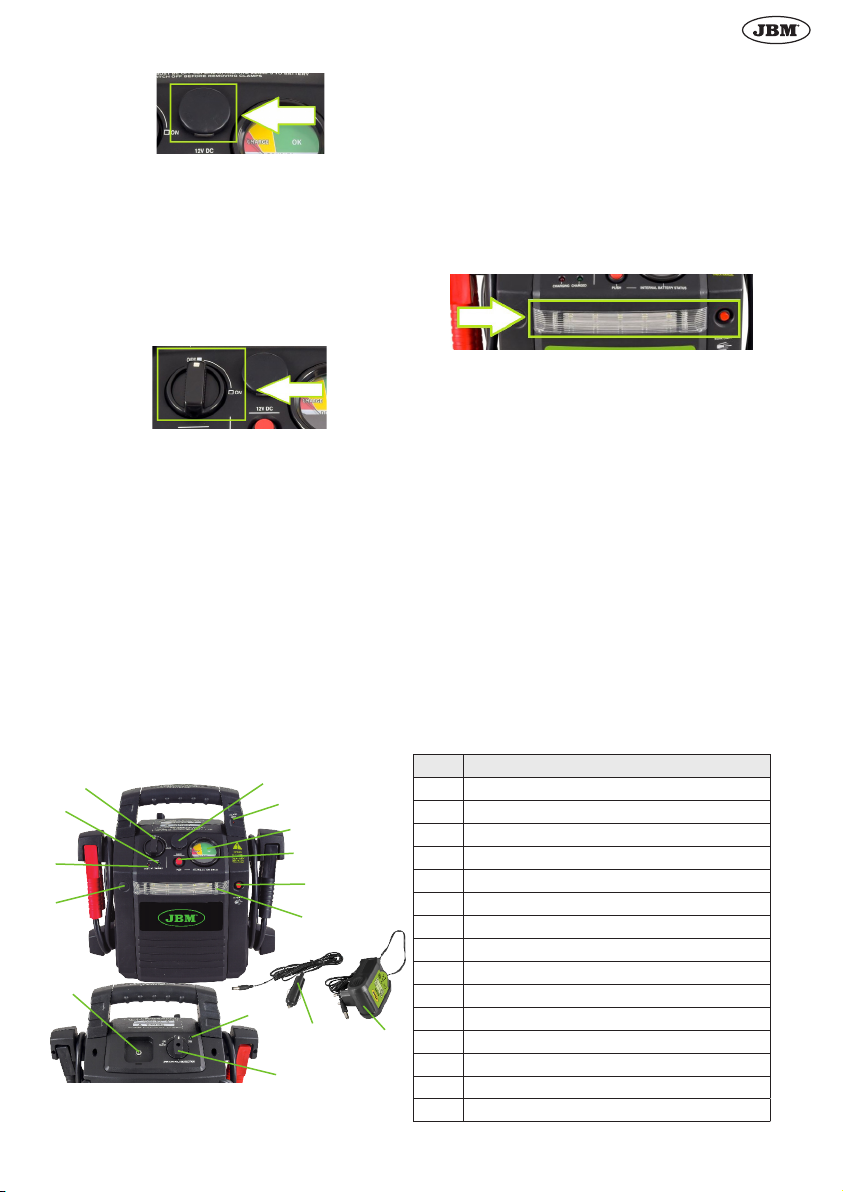
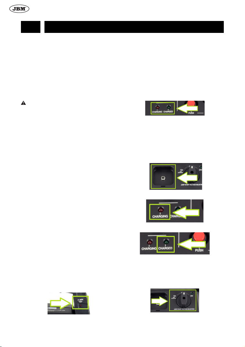
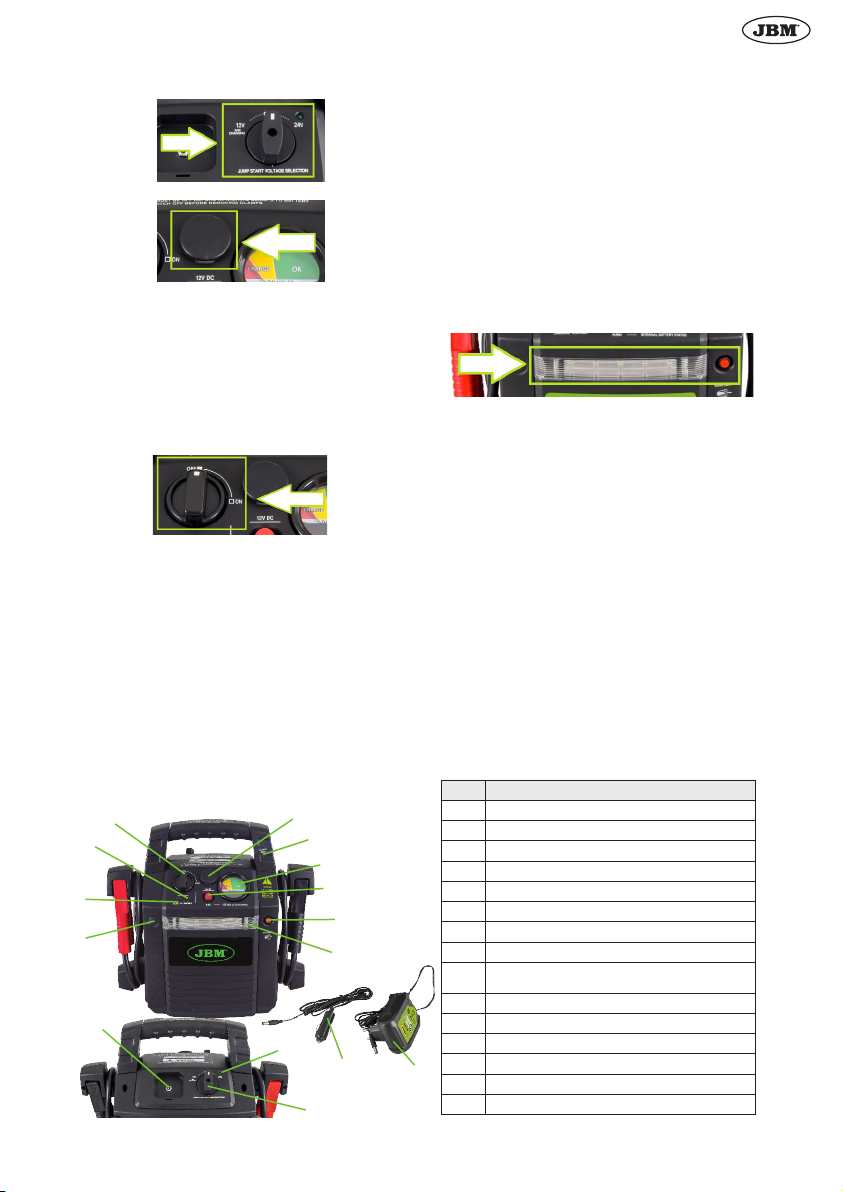
1. Die Warnanzeige (7) ändert die Farbe mit der unters-
chiedlichen Frequenz und informiert den Bediener:
• Wenn die Klemmen an den Batterieklemmen richtig
angeschlossen sind, leuchtet die Anzeige grün.
• Wenn die Anzeigt inkorrekt angeschlossen ist, blinkt
sie mit zwei roten Blitzen pro Sekunde, und es ertönt
ein Signalton.
• Beim Anschluss ans Fahrzeug mit einem 24 V-Bord-
netz, wenn der Schalter auf “12 V” eingestellt ist,
blinkt die Anzeige mit zwei roten Blitzen pro Sekun-
de, und es ertönt ein Signalton.
2. Wenn die Spannung der internen Batterie zu niedrig ist,
blinkt die Ladestatusanzeige (3) rot.
3. Um den Starter wieder aufzuladen, muss sich der 12/24
V-Modusschalter (12) in der Position “12 V” benden.
Wenn der Benutzer den Schalter auf “OFF” oder “24V”
stellt, blinkt die Ladestatusanzeige mit 3 und 4 roten
und grünen Blitzen, und es ertönt ein Signalton.
BETRIEB
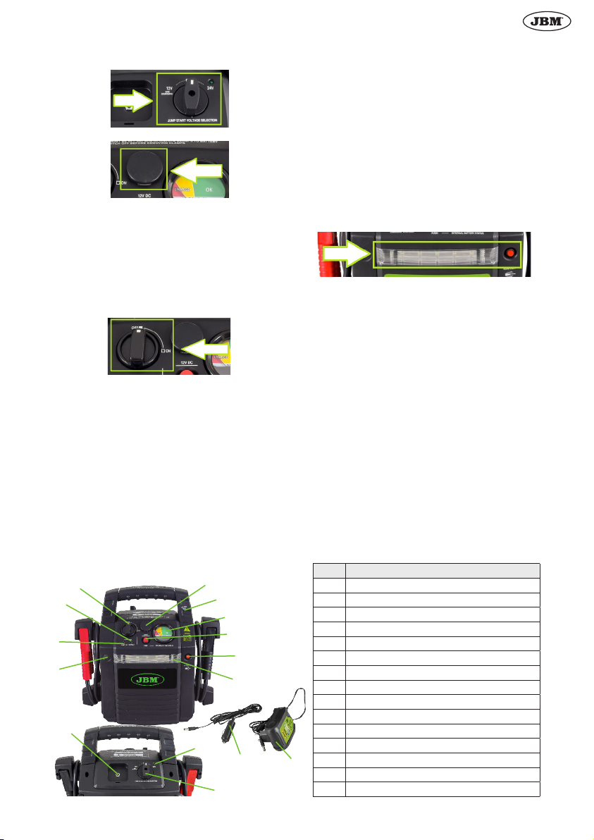
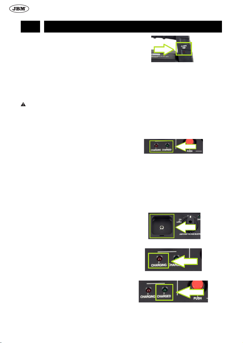
Auaden des Starters
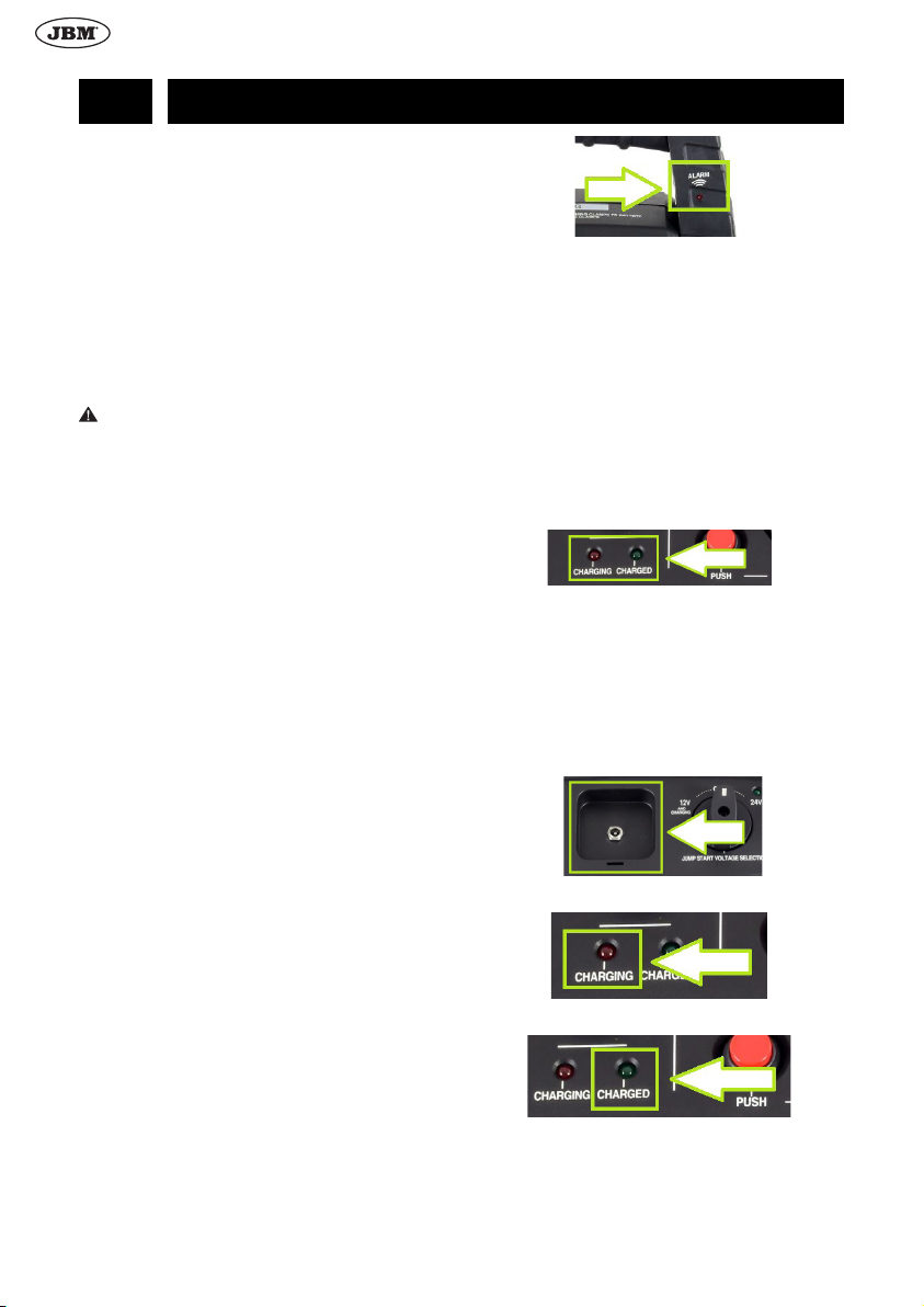
HINWEIS! Überprüfen Sie den Zustand der internen Strom-
versorgung durch das Drücken der Prüftaste (9) und die
Kontrolle der Voltmeteranzeigen (8) vor der ersten Inbetrieb-
nahme. Wenn die rote Ladeanzeige aueuchtet, laden Sie
das Gerät so schnell wie möglich auf.
1. Schließen Sie das Ladegerät an die Stromversorgung
an.
2. Stecken Sie den Stecker des Ladegeräts in die Lades-
teckdose (11).
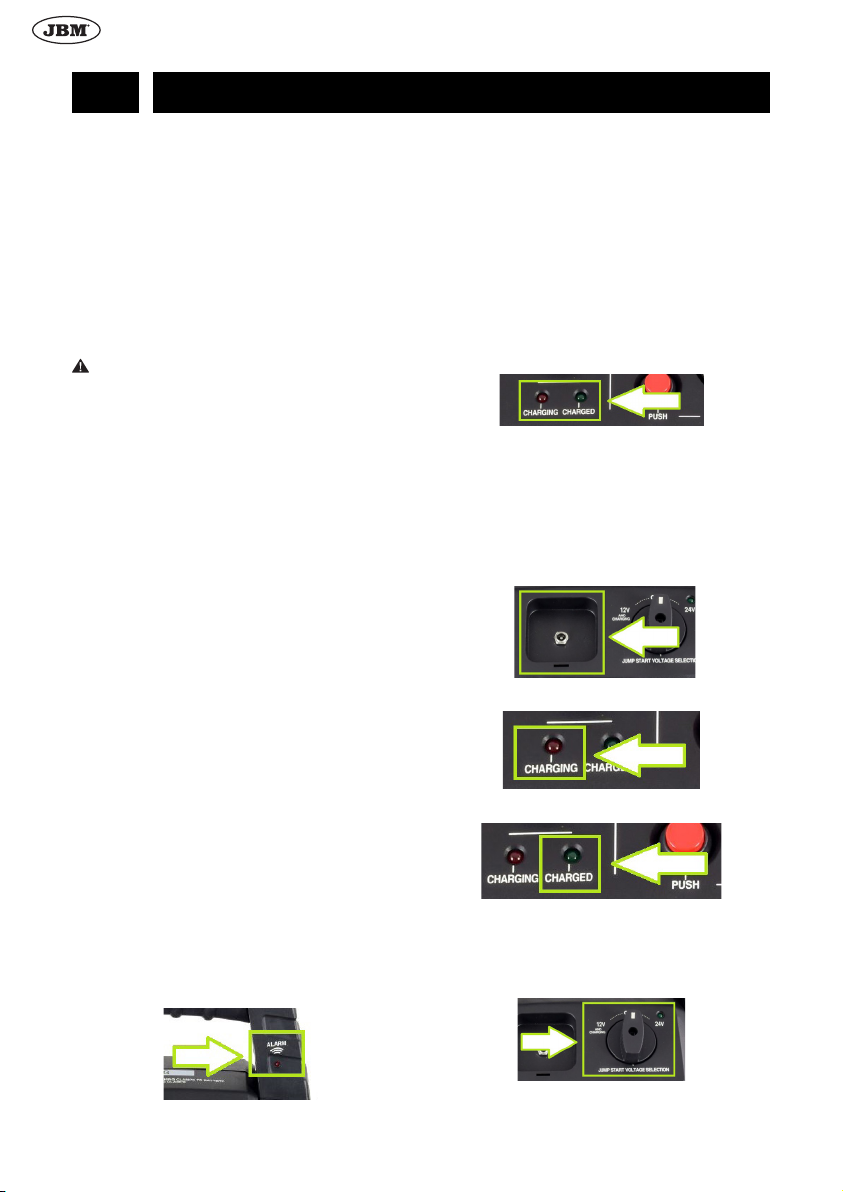
3. Die LED-Anzeige (3) leuchtet auf, nachdem die La-
dung des Starters begonnen hat.
4. Die LED-Anzeige (4) leuchtet auf, nachdem der Starter
vollständig geladen ist.
5. Trennen Sie ein Ende des Ladegeräts von der Steck-
dose und das andere Ende von der Stromversorgung.
12 V DC-Steckdose
Der Starter kann zum Laden von Geräten verwendet wer-