JCM SATURN MKII User manual

SATURN MKIIe
Instructionsg
Produced by JCM Seating Solutions Ltd
Issue Number 3 : October 2001

SATURN CHAIR INSTRUCTION MANUAL
Contents Page
Page 1: Introduction.
Page 2: Height and Tilt Adjustment – Gas Spring.
Page 3: Height Adjustment – Hydraulic Ram.
Page 4: Height and Tilt Adjustment – Electric Motor.
Page 5: Adjusting the Back Height and the Lateral Supports.
Page 6: Hip Pad and Back Angle Adjustment.
Page 7: Arm Rest Position Adjustment.
Page 8: Seat Depth and Split Seat Positional Adjustment
Page 9: Adjusting Head Rest Positioning.
Page 10: Adjusting Footplate Positioning.
Page 11: Applying Brakes and Removing Castors.
Page 12: Cleaning, Care and Maintenance Instructions.
Page 13: Servicing and Inspection Instructions – Service Record.
Page 14: Inspecting and Re-Issuing Instructions.
Page 15: JCM Accessories and Accessory Instructions.

SATURN CHAIR INSTRUCTION MANUAL
Introduction
Please read all the information contained in this manual before first using the Seating System and retain for future
reference.
The Saturn Seating System is available in four sizes, all of which are on a moveable base and offer a vast array of
positional adjustment. The seating system is designed to provide comfort and postural support and as such is
supplied via qualified professionals who will have undertaken the necessary adjustment to provide the required
support for the individual user. The seating system should therefore never be adjusted or used by any other person
without the input from a suitably qualified professional person. The seating system is not intended for those who
have significant athetosis.
The following pages provide guidance on the versatile adjustment for reference by these professionals, but also they
provide information about how the seating system should be used, maintained, and which parts should be regularly
checked for security of attachment.
Within the manual there are important points to note which are identified by the following symbol:
IMPORTANT
The degree of maintenance required is largely dependent upon the frequency of use, how active the user is, and the
effects of others who mistakenly operate this chair. In some instance, daily checking of security and correct
adjustment may be necessary. If it is likely that the hand-wheels will be repeatedly loosened, JCM can supply Allen
Key Bolts as an alternative. We strongly recommend this if there is a danger from those in the vicinity of the user.
IMPORTANT
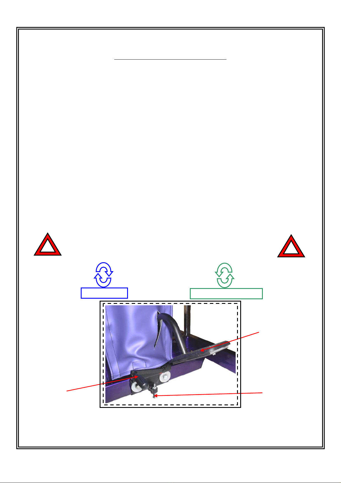
The mobile base is intended for indoor use only. Whilst the seating system is stable on a 5-degree slope, even in its
most upright position, it is not intended to be used in this manner. It is however, intended to be used on a level flat
floor, where movement is confined to a single room. For safety ALWAYS lower before moving.
NOTE: that heavy items on the tray will affect stability. The fitting of anything other than the standard JCM tray
may substantially affect the stability of the seating system and should therefore be checked before issue.
IMPORTANT
Note the cleaning, care and maintenance information on page 11.
IMPORTANT
If at any time it is noted that areas of the Users skin remain red after being out of the seating system for 10 minutes,
contact the qualified professional who performed the fitting. It may be a sign that there is excessive pressure being
applied by the padding. This could occur due to initial use, where further corrective adjustment may be needed, or
due to growth of the child.
PAGE 1

SATURN CHAIR INSTRUCTION MANUAL
Adjusting Height/ Tilt of Chair – Gas Spring
Reference: Figure 1 – Height and Tilt Adjustment (Gas Piston).
Arrow 1:
Pulling and holding this lever inwards whilst controlling the chair by the grab handles enables you to alter the seats
tilt/prone angle. The chair has been designed to offer a substantial variation of positioning and support, which the
tilt/prone angle mechanism can help to demonstrate. The chair can be positioned at any point within this range to
suit whatever situation. The chair offers around 20 degrees of tilt movement and approximately 15 degrees of prone
movement.
Arrow 2:
Pulling and holding this lever inwards whilst controlling the chair by the grab handles enables you to alter the seats
vertical height. The chair has been designed to fit under nursery tables and raise high enough for positioning at
dining room tables. The chair can be positioned at any point within this range to suit whatever situation.
IMPORTANT
Always ensure that the height/tilt mechanism is free from obstruction before operating this chair.
Never Over Adjust or Over Tighten Moving Parts!
Figure 1 – Height and Tilt Adjustment.
Page 2
Arrow 1 Arrow 2

SATURN CHAIR INSTRUCTION MANUAL
Adjusting Height/ Tilt of Chair – Hydraulic Ram
Reference: Figure 2 – Height and Tilt Adjustment (Hydraulic).
Arrow 1:
The Lever indicated by Arrow 1 is a foot pedal used for heightening of the chair. To operate the height adjustment
you should first check that the lever indicated by Arrow 2 is locked securely in place by turning it in a clockwise
direction. Once secure the chair can be raised to the desired position by continually pumping on Lever 1 using one
of your feet. It is important that you stop to pump the lever whenever you reach a position of resistance, inspect the
chair for obstruction and ensure you haven’t reached the maximum height.
Arrow 2:
Lever 2 enables you to release the chair and lower it to its home position. To lower the chair you should turn lever 2
in an Anti Clockwise direction until the chair starts to contract to its lowest position. Whilst performing this
operation ensure that the chair mechanism is free from obstruction and assist the lowering by holding the chair at the
grab rails. To Re-Raise the chair Lever 2 will need to be secured tight again by turning and locking it in the
clockwise direction.
Arrow 3:
Lever 3 enables you to adjust the movement of Lever 2 in order to ensure a gradual decline to the lowest position.
On first lowering the chair its is recommended that the operator releases Lever 2 gradually until a steady decline
speed is achieved (Chair should be Loaded.) When the desired speed has been achieved you should set the
adjustment Lever 3 to this position in order to stop over adjustment of Lever 2. JCM Seating set this lever on
leaving the factory using a weight limit of 40Kgs. If this proves unsuitable then the adjustment has been provided
for operator purposes.
IMPORTANT
Always ensure that the height mechanism is free from obstruction before operating this chair.
Never Over Adjust or Over Tighten Moving Parts!
Figure 2 – Height and Tilt Adjustment (Hydraulic).
Page 3
Arrow 2
Arrow 1
Arrow 3
CLOCKWISE
A
N
TI -
C
L
OC
K
W
I
S
E

SATURN CHAIR INSTRUCTION MANUAL
Adjusting Height/ Tilt of Chair – Electric Motors
Reference: Figure 3 – Height and Tilt Adjustment (Electric).
Button 1: Pressing and holding this button downwards enables you to raise the seat height position.
Button 2: Pressing and holding this button downwards enables you to lower the seat height position.
Button 3: Pressing and holding this button downwards enables you to alter the tilt angle of the chair.
Button 4: Pressing and holding this button downwards enables you to alter the prone angle of the chair.
The chair has been designed to offer a substantial variation of positioning and support, which the tilt/prone angle
and height adjustment mechanism can help to demonstrate. The chair can be positioned at any point within this
range to suit whatever situation. The chair is fitted with limit switches to restrict the motors in certain positions.
Please ensure that the footplates are raised from the ground before moving the chair so as not to damage one
of these switches.
IMPORTANT
Always ensure that the motor is plugged into the mains supply before operating this chair.
Never Over Adjust or Over Tighten Moving Parts!
IMPORTANT
Always ensure that Adjustment Mechanism is free from Obstruction before operating this chair.
Never Over Adjust or Over Tighten Moving Parts!
Figure 3 – Height and Tilt Adjustment (Electric).
Page 4
Arrow 4
Arrow 3
Arrow 2
Arrow 1

SATURN CHAIR INSTRUCTION MANUAL
Adjusting Back Height and Lateral Supports
Reference: Figure 4 – Back Height and Lateral Support Adjustment.
Arrow 1:
Turning these levers anti-clockwise enables you to adjust the height of the Lateral support. The height of the
support should be adjusted to fit the size of child and seat them in comfort. Once a suitable position has been found
the levers should then be re-tightened by gently turning in the clockwise direction.
Arrow 3:
Turning these levers anti-clockwise enables you to adjust the height of the back support. The height of the back
should be adjusted to fit the size of child and seat them in comfort. Once a suitable position has been found the
levers should then be re-tightened by gently turning in the clockwise direction.
Arrow 5:
Turning this lever anti-clockwise enables you to adjust the angle of the lateral support. Once the required position
has been found the lever should then be re-tightened by gently turning in the clockwise direction.
Arrow 6:
Turning this lever anti-clockwise enables you to adjust the width of the lateral support. Once the required position
has been found the Lever should then be re-tightened by gently turning in the clockwise direction.
IMPORTANT
Always ensure that the back and lateral supports are completely locked into position before operating this chair.
Never Over Adjust or Over Tighten Moving Parts!
Figure 4 – Back Height and Lateral Support Adjustment.
Page 5
Arrow 6
Arrow 5
Arrows 3 & 4
Arrows 1 & 2
CLOCKWISE
ANTI
-
CLOCKWISE

SATURN CHAIR INSTRUCTION MANUAL
Adjusting Hip Pads and Back Angle Recline
Reference: Figure 5 – Hip Pad and Back Angle Adjustment.
Arrow 1:
Turning this lever anti-clockwise enables you to adjust the position of the hip pad. The pads can be extended to seat
the child and then fitted close to provide suitable support and comfort. Once a suitable position has been found the
lever should then be re-tightened by turning in the clockwise direction.
Arrow 2:
The lever indicated by Arrow 2 enables you to alter the back recline of your seating system. Identical levers are
situated on either side of the chair frame and they should both be used to adjust the reclined position. Pulling the
levers outward whilst supporting the back recline enables you to manual adjust the position. When a suitable
position has been found the levers should be released and the back adjusted until it has locked into position. The
Back mechanism allows for 40 degrees recline and 10 degrees prone angle adjustment. To make the operation
easier the levers are provided with a locking mechanism, the lever should be pulled outward and rotated by 90
degrees, locking the lever in its open position. JCM recommend that you do this with one side only while manually
holding out the other lever and adjusting the back. When the desired position has been achieved turning again by 90
degrees should close the lever, which has been left open.
IMPORTANT
Always ensure that the back support is completely locked into position before operating this chair.
Never Over Adjust or Over Tighten Moving Parts!
ANTI
-
CLOCKWISE
C
L
OC
K
W
I
S
E
Figure 5 – Hip Pad and Back Angle Adjustment.
Page 6
Arrow 1
Arrow 2

SATURN CHAIR INSTRUCTION MANUAL
Adjusting Arm Rest Positioning
Reference: Figure 6 – Arm Rest Positional Adjustment.
Arrow 1:
Turning this lever anti-clockwise enables you to adjust the angle at which the armrest sits. Once a suitable position
has been found the lever should then be re-tightened by gently turning in the clockwise direction.
The button on the lever enables the user to adjust the position of the lever. The lever should be pulled outward and
turned to the required position.
Arrow 2:
Turning this lever anti-clockwise enables you to adjust the height at which the armrest sits. Once the required
position has been found the lever should then be re-tightened by gently turning in the clockwise direction.
IMPORTANT
Always ensure that the Arm Rest is completely locked into position before operating this chair.
Never Over Adjust or Over Tighten Moving Parts!
C
L
OC
K
W
I
S
E
ANTI
-
CLOCKWISE
Figure 6 – Arm Rest Positional Adjustment.
Page 7
Arrow 1
Arm Rest
Arrow 2

SATURN CHAIR INSTRUCTION MANUAL
Adjusting Seat Depth and Split Seat Positioning
Reference: Figure 7 – Seat Depth and Split Seat Positional Adjustment.
Arrow 1:
Turning the levers indicated by Arrow 1 anti-clockwise enables you to adjust the amount of Seat Depth provided.
The loosened hand wheels enable the user to manually adjust the position of the back support and therefore alter the
seat depth. To achieve the maximum seat depth the back support should be pulled out to its maximum position and
then locked into place by gently turning the hand wheels back in the clockwise direction. To acquire the minimum
seat depth the user should push the back support close up to the seat frame and then re-tighten the hand wheels by
turning gently in the clockwise direction.
Arrow 2:
If your chair is fitted with a split seat, it can be easily adjusted using the hand wheels indicated by Arrow 2. Simply
loosen the levers by turning in the anti-clockwise direction and then manually position the relevant section of seat by
easing it away from the chair frame. Once the required position of support has been achieved the mechanism should
be locked into place by gently re-tightening the hand wheels, turning in the clockwise direction.
IMPORTANT
Always ensure that the Back Support and Seat are completely locked into position before operating this chair.
Never Over Adjust or Over Tighten Moving Parts!
C
L
OC
K
W
I
S
E
ANTI
-
CLOCKWISE
Arrow 1
Figure 7 – Seat Depth Positional Adjustment.
Page 8
Arrow 2

SATURN CHAIR INSTRUCTION MANUAL
Adjusting Head Rest Positioning
Reference: Figure 8 – Head Rest Positional Adjustment.
Arrow 1
Arrows 1 and 2 should be operated together to provide the best head positioning for the child seated. The head
support can also be taken out of the frame and turned around to provide even greater variation of support.
Turning these levers anti-clockwise enables you to adjust the angle/position of the head support. Once the required
position has been found the levers should then be re-tightened by gently turning in the clockwise direction.
The button on levers 1 and 2 enables the user to adjust the position of the lever. The lever should be pulled outward
and turned to the required position.
Arrow 3:
To adjust the vertical positioning of the headrest, simply turn this lever anti-clockwise and raise/lower the support to
a suitable position. Once the required position has been found the lever should then be re-tightened by gently turning
in the clockwise direction.
IMPORTANT
Always ensure that the Head Support is completely locked into position before operating this chair.
Never Over Adjust or Over Tighten Moving Parts!
CLOCKWISE
ANTI
-
CLOCKWISE
Figure 8 – Head Rest Positional Adjustment.
Page 9
Arrow 2
Arrow 1
Arrow 3

SATURN CHAIR INSTRUCTION MANUAL
Adjusting the Footplate Positioning
Reference: Figure 9 – Footplate Positional Adjustment.
Arrow 1:
Turning this lever anti-clockwise enables you to adjust the vertical position of the Foot Plate. The footplate can be
extended to suit the child and provide suitable support and comfort. Once the desired position has been found the
lever should then be re-tightened by gently turning in the clockwise direction.
Arrow 2:
The Foot Plates can be flipped out of the way by simply pushing them up towards the frame. This is shown by the
direction of Arrow 2.
IMPORTANT
Always ensure that the Footplate is completely locked into position before operating this chair.
Never Over Adjust or Over Tighten Moving Parts!
C
L
OC
K
W
I
S
E
ANTI
-
CLOCKWISE
Figure 9 – Footplate Positional Adjustment.
Page 10
Arrow 1
Arrow 2

SATURN CHAIR INSTRUCTION MANUAL
Applying Brakes and Replacing Castors
Reference: Figure 10 – Brake Application and Castor Replacement.
Arrow 1:
Suppressing this lever with the foot will apply the brake to the castor. When all four brakes are applied the chair is
rigid in position. To remove the brakes simply flick lever 1 back up using the foot.
Arrow 2:
Castors can be simply removed by placing the chair on its side and by pulling the castor away from the frame. This
should only be necessary if for some reason the castor is damaged. Replacement castors can be purchased using the
companies ordering system.
IMPORTANT
Always ensure that the Castors are completely locked into position before operating this chair.
Never Over Adjust or Over Tighten Moving Parts!
Figure 10 – Brake Application and Castor Replacement.
Page 11
Arrow 1
Arrow 2

SATURN CHAIR INSTRUCTION MANUAL
Cleaning and Care Instructions
The fabric used on your Saturn chair can be:
•Wiped with a mild detergent.
•Washed or Dry Cleaned using detergent up to a maximum temperature of 60 Degrees Celsius.
•Do not use bleach or biological or phenolic based cleaners.
•Dry completely before use.
•It is possible that some surface wrinkling may occur.
IMPORTANT
Maintenance
We encourage the use of the service history log record, which can be found on the following page. The degree of
maintenance required is largely dependent upon the frequency of use, how active the user is, and the effects of
others who mistakenly operate this chair. In some instance, daily checking of security and correct adjustment may
be necessary. Reference to the earlier pages of this manual will identify all points that should be checked for fitting
and security. In addition a detailed inspection of the following should be checked at least annually.
•Castor Wheels: Lift base and check each wheel to ensure it is not loose or worn.
•Castor Brakes: Removing any grease or dirt that has built up on the wheels, check that the brakes stop the
wheels rotating.
•Seat Tilt Mechanism: With the tilt lock released check for free movement with no signs of wear. Tighten
the lock and ensure it holds the seat angle.
•Hi-Low Base Height Adjustment: With the seat unloaded press the lever and ensure that it moves freely
to the maximum height. Place the appropriate maximum load (40, 60, 80 or 100kgs) and, over a period of
time (approximately 10 —15 minutes), check that there is no creep (lowering) of the seat. With the load on,
press the lever and ensure the seat travels freely to the lowest position.
•Seat / Backrest Upholstery: Check the attachment points of the seat and backrest upholstery, for
tightness. Check for wear or worn covering, rough worn upholstery can cause discomfort, would be
difficult to keep hygienically clean, and might cause skin irritation.
•Frame & Fixtures General: Check for signs of fatigue wears, replacing parts that show signs of wear or
repeatedly becoming loose. With correct maintenance the frame should provide at least 5 years trouble free
use but, depending on conditions of use, wear will occur and a thorough inspection is recommended.
•Check all metal parts for signs of wear, paying particular attention to adjustable/moving parts.
•Check Arm Pads and Headrest, replace if worn.
•Check Tray for damage. Trays with black edge rails are fitted with D shaped blanking end caps. They are
held in place by an inference fit and an adhesive, if these are loose they should be removed, all surfaces
cleaned and an appropriate adhesive applied, following the adhesive instructions. Alternatively if the Tray
is worn, replace with the new tray, which has solid silver coloured rails. If the tray is damaged with any
rough or sharp corners, it should also be replaced.
•Maximum Loading on a Saturn chair should not exceed:
SATURN 1 – 40 Kgs SATURN 2 – 60 Kgs SATURN 3 – 80 Kgs SATURN 4 – 100 Kgs
IMPORTANT
JCM Seating Solutions Ltd will not be held responsible for incorrect use of this chair.
PAGE 12

SATURN CHAIR INSTRUCTION MANUAL
Servicing and Inspection Instructions
JCM Seating Solutions Ltd recommend that an inspection of this product is completed once every 6 Months. If any
fault is found that could provide a hazard to either the occupier or the operator then the chair should not be used
until the product has been repaired. A competent person who preferably has experience of this type of product
should carry out the service. The growth and any changes of the occupants needs since the original assessment
should also be taken into account when servicing this product.
The table below has been provided for recording of relevant data regarding these inspections.
Date Service Performed Signature Print Name
IMPORTANT
JCM Seating Solutions Ltd will require proof of service for any Warranty Orders
Chair Serial Number:
Date Delivered:
Battery Use By Date:
PAGE 13

SATURN CHAIR INSTRUCTION MANUAL
Inspecting and Reissuing the Product
Most JCM Products are individually assessed for a client upon issuing. We therefore recommend that the following
points be adhered to before reissuing of this product.
•Check that there is no chance of cross infection due to poor cleaning, taking into account the condition of
the fabric and the foam inside.
•Check the chair is suitable for the clients needs, taking into account age, weight and type of disability.
JCM products are not suitable for people with severe behavioural problems.
•Ensure that the instruction manuals are passed onto the new user and that the inspection service record is up
to date.
•Ensure the frame and accessories are free of distortion or excessive wear.
•Check that the wheels are secure and that the brakes are in a good working condition.
•If the chair has a tray, inspect the tray to ensure there is no damage that could be a hazard to the user.
•Ensure that all the functions of the chair are working correctly i.e. tilt, height adjustment or back recline,
etc.
•Check that hand wheels and levers are in good condition and fitted securely.
•Always ensure that the chair is packaged correctly before delivering.
IMPORTANT
JCM Seating Solutions Ltd will not be held responsible for incorrect use of this chair.
PAGE 14

SATURN CHAIR INSTRUCTION MANUAL
JCM Accessory Listing
Moore Head Support
Should only be adjusted by a therapist or competent person who understands the product and its principals. The
prongs on the Head Support should never be tight around the head. Check that the prongs are NOT set near the eyes
or infringe behind the ears. The foam covering the prongs should be inspected regularly and if damaged replaced.
Multi Adjustable Head support
Wings on the head support are ideally set at 45 degrees. Do NOT bring the wings in tight to the head.
Ensure that the head support is set in such away that the child cannot loop their head around the wings and get stuck.
Flexi-Supports and Lateral Supports
Check that when fitting this type of support the straps do not infringe on any feeding tubes the child may have.
Lap Strap
Always check that the child’s pelvis is symmetrical and at the back of the seat. Fit at reasonable tension for security.
Never leave a child in a chair unattended without the lap strap being fastened.
Pommel
The pommel is designed to abduct the users knees to help keep the hips in a good position. Do NOT use the pommel
as a way of holding the user in the seat. Remove the pommel when transferring the user in and out of the seat.
Knee Blocks
Knee blocks are designed to abduct the knees and keep the hips in a good position. The pelvis should always be well
positioned and the lap strap fastened before fitting the knee blocks. Do NOT use knee blocks without fixing the
users feet with foot sandals or straps. If the user extends in the chair this may injure the knee.
Never use knee blocks unless you are familiar with the user and know the condition of their hips. If the user has any
known medical problem, relating to their hips, consult with a therapist.
Foot Sandals and Straps
Should only be fixed when the user is wearing shoes or boots.
Tray
Do NOT use the tray as away of securing children in a chair always ensure that the lap strap and any other straps
supplied are used. Ensure that the tray clips are secure on both sides of the tray. If the tray is damaged, ensure that
this will not be a hazard to the user. Never leave hot items on the tray while children are unattended.
IMPORTANT
JCM Seating Solutions Ltd will not be held responsible for incorrect use of this chair.
Ensure all Adjustment mechanisms are Secure and in place before operation.
Page 15
Other JCM Indoor Furnishing manuals
Popular Indoor Furnishing manuals by other brands

Style selections
Style selections CL22-11ST8-W manual

Furniture of America
Furniture of America CM3059T-3PK Assembly instructions

Forte
Forte FRTB01 Assembling Instruction

Williams-Sonoma
Williams-Sonoma Penn 3 Seater Sofa Assembly instructions

World Market
World Market ALICANTE II 597208 Assembly instructions

Case
Case Tanso 102356 instructions

Living Spaces
Living Spaces 17C258A-W-S Assembly instruction

Galipette
Galipette LITTLE TOWN P69 Assembly instructions

Triarch
Triarch Indoor Lighting 31414 Assembly instructions

INGENIA
INGENIA PRISMA 42.74 manual

Whalen
Whalen AVCBEC60-SMB Instruction booklet

Dedeman
Dedeman BARLETTA 120 Assembling Instruction