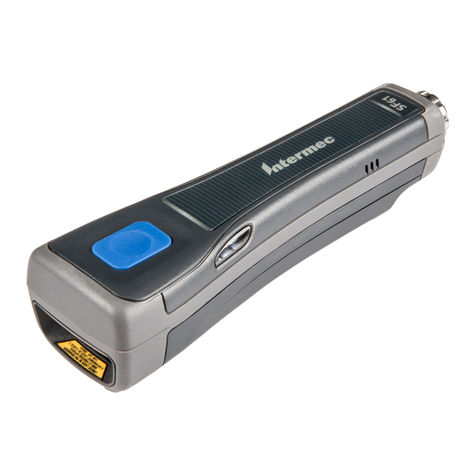
JDiag FasDiag JD301 User manual

FasDiag JD301/316
User Manual
OBDII Car Diagnostic Scanner

1. General Information
•On-Board Diagnostics (OBD) II
The OBD II system is designed to monitor emission control systems
and key engine components by performing either continuous or
periodic tests of specific components and vehicle conditions. When a
problem is detected, the OBD II system turns on a warning lamp
(MIL) on the vehicle instrument panel to alert the driver typically by
the phrase of “Check Engine” or “Service Engine Soon”. The system
will also store important information about the detected malfunction
so that a technician can accurately find and fix the problem. Here
below follow three pieces of such valuable information:
•Whether the Malfunction Indicator Light (MIL) is commanded
'on' or 'off';
•Which, if any, Diagnostic Trouble Codes (DTCs) are stored;
•Readiness Monitor status.
•Diagnostic Trouble Codes (DTCs)
OBD II Diagnostic Trouble Codes are codes that are stored by
theon-board computer diagnostic system in response to a problem
found in the vehicle. These codes identify a particular problem area
and are intended to provide you with a guide as to where a fault
might be occurring within a vehicle. Here below is an example to

illustrate the structure of the digits:
•Location of the Data Link Connector (DLC)
The DLC (Data Link Connector or Diagnostic Link Connector) is the
standardized 16-cavity connector where diagnostic scan tools
interface with the vehicle's on-board computer. The DLC is usually
located 12 inches from the center of the instrument panel (dash),
under or around the driver's side for most vehicles. If Data Link
Connector is not located under dashboard, a label should be there
telling location. For some Asian and European vehicles, the DLC is
located behind the ashtray and the ashtray must be removed to
access the connector. If the DLC cannot be found, refer to the
vehicle's service manual for the location.

•OBD II Readiness Monitors
An important part of a vehicle's OBD II system is the Readiness
Monitors, which are indicators used to find out if all of the emissions
components have been evaluated by the OBD II system. They are
running periodic tests on specific systems and components to ensure
that they are performing within allowable limits.
Currently, there are eleven OBD II Readiness Monitors (or I/M
Monitors) defined by the U.S. Environmental Protection Agency
(EPA). Not all monitors are supported by all vehicles and the exact
number of monitors in any vehicle depends on the motor vehicle
manufacturer's emissions control strategy.
Continuous Monitors -- Some of the vehicle components or systems
are continuously tested by the vehicle's OBD II system, while others
are tested only under specific vehicle operating conditions. The
continuously monitored components listed below are always ready:
1. Misfire
2. Fuel System
3. Comprehensive Components (CCM)
Once the vehicle is running, the OBD II system is continuously
checking the above components, monitoring key engine sensors,
watching for engine misfire, and monitoring fuel demands.
Non-Continuous Monitors - Unlike the continuous monitors, many
emissions and engine system components require the vehicle to be

operated under specific conditions before the monitor is ready.
These monitors are termed non-continuous monitors. For different
ignition type engines, the available monitors are different too.
The following monitors are to be used for spark ignition engines only
1. EGR System
2. O2 Sensors
3. Catalyst
4. Evaporative System
5. O2 Sensor Heater
6. Secondary air
7. Heated Catalyst
The following monitors are to be used for compression ignition
engines only:
1. EGR System
2. NMHC Catalyst
3. NOx aftertreatment
4. Boost pressure system
5. Exhaust gas sensor

6. PM filter
•OBD II Monitor Readiness Status
OBD II systems must indicate whether or not the vehicle's PCM's
monitor system has completed testing on each component.
Components that have been tested will be reported as “Ready”, or
“Complete”, meaning they have been tested by the OBD II system.
The purpose of recording readiness status is to allow inspectors to
determine if the vehicle's OBD II system has tested all the
components and/or systems.
•OBD II Definitions
Power-train Control Module (PCM) - OBD II terminology for the on-
board computer that controls engine and drive train. Malfunction
Indicator Light (MIL) - Malfunction Indicator Light (Service Engine
Soon, Check Engine) is a term used for the light on the instrument
panel.
OBD II Drive Cycle - A specific mode of vehicle operation that
provides vehicle to the “ready” condition.
Freeze Frame Data - When an emissions related fault occurs, the
OBD II system not only sets a code but also records a snapshot of
the vehicle operating parameters to help in identifying the problem.
•OBD II Modes of Operation

Here is a basic introduction to the OBD II communication protocol.
Mode byte: The first byte in the stream is the mode number. There
ar 9 modes for diagnostic requests, so this first byte is from 1 to 9.
The first byte in the response data bytes is this same number plus 64.
For example, a mode 1 request would have the first data byte = 1,
and the response would have the first data byte = 65.
2. Using the Scan Tool
•Tool Description
①OBD II CONNECTOR – Connects the scan tool to the vehicle's Data
Link Connector (DLC).

②YELLOW LED – Indicates there is a possible problem. A “Pending”
DTC is present and/or some of the vehicle's emission monitors
have not run their diagnostic testing.
③GREEN LED – Indicates that engine systems are running normally
(The number of monitors on the vehicle which are active and
performing their diagnostic testing is in the allowed limit, and no
DTCs are present).
④RED LED – Indicates there is a problem in one or more of the
vehicle's systems. The red LED is also used to show that DTCs are
present. DTCs are shown on the Scan Tool's display.In this case,
the MIL lamp on the vehicle’s instrument panel will light steady on.
⑤LCD DISPLAY – Indicates test results.
⑥IM BUTTON – I/M Readniess function.
⑦UP BUTTON – Scrolls up through menu items.
⑧EXIT BUTTON – EXIT function screen.
⑨ENTER BUTTON – Enter function screen.
⑩DOWN BUTTON - Scrolls down through menu items.
•Specifications
1) Display: 2.4 inch TFT color display
2) Operating Temperature: 0 to 60°C (32 to 140 F°)
3) Storage Temperature: -20 to 70°C (-4 to 158 F°)
4) External Power: 8.0 to 18.0 V power provided via vehicle battery

5) Dimensions:
Length Width Height
117 mm (4.61”) 72 mm (2.83”) 18 mm (0.71”)
6) NW: 0.18kg (0.39lb), GW: 0.21 kg(0.46lb)
•Accessories Included
A. User’s Manual - Instructions on tool operations.
B. OBD2 cable - Provides power to tool and communicates between
tool and vehicle.
•Navigation Characters
Characters used to help navigate the scan tool are:
• “#” -- Identifies the control module number from which data is
retrieved.
•“Pd” – Identifies a pending DTC when viewing DTCs.
•Keyboard
No solvents such as alcohol are allowed to clean the keypad or
display. Use a mild nonabrasive detergent and a soft cotton cloth.
Do not soak the keypad as the keypad is not waterproof.
•Power
The scan tool is powered via the vehicle Data Link Connector (DLC).
Just follow the steps below to turn on the scan tool:

A. Locate DLC on vehicle.
•A plastic DLC cover may be found for some vehicles and you
need to remove it before plugging the OBD2 cable.
B. Plug the tool's OBD II cable to the vehicle's DLC.
•System Setup
The scan tool allows you to make the following adjustments and
settings:
1. Language: Selects the desired language.
2. Configure Monitors: Sets the monitors you want to test.
3. Unit of measure: Sets the unit of measure to English or Metric.
4. Key Beep Set: Turns on/off key-press beep.
5. Status Beep Set: Turns on/off the I/M Readiness Status beep.
6. Tool Self-test: Checks if the LCD display, LED lamps and keyboard
are working normally.
7. Update Mode: Accesses the Update Mode.
8. Settings of the unit will remain until change to the existing settings
made.
To enter the Setup menu

When the scan tool is powered on, it displays a Main Screen.
From the Main Screen: Use the Direction button to select Set up, and
press the OK button. Follow the instructions to make adjustments an
settings as described in the above setup options.
•Language Setup
1. English is the default language.
2. From System Setup screen, use the Direction button to select
Language, and press the OK button.
3. Use the Direction button to select the desired language and press
the OK button to save your selection and return to previous
screen. We provide three language options currently.
•Configure Monitors
From System Setup screen, use the Direction button to select
Configure Monitors, and press the OK button.
•Key Beep Set

This function allows you to turn on/off the build-in speaker for key
pressing.
◆The default setting is Beep On.
1. From System Setup screen, use the Direction button to sele Key
Beep Set and press the OK button.
2. From Key Beep Set menu, use the Direction button to select Beep
ON or Beep OFF to turn on/off the beep.
3. Press the OK button to save your selection and return to previous
menu.
•Status Beep Set
•The default setting is Beep
This function allows you to turn on/off the build-in speaker for the
LEDs in diagnostic testing. Different audio tone corresponds to
different LED lamp. This function is invaluable when working in bright
areas where LED illumination alone is not sufficient.
◆From System Setup screen, use the Direction button to sele
Status Beep Set and press the OK button.
◆From Status Beep Set menu, use the Direction button to select
Beep ON or Beep OFF to turn on/off the beep.
•Tool Self-test
The Tool Self-test function checks if the display, LED lam and
keyboard are working properly.
•Display test

The Display Test function checks if the LCD display is working
normally.
◆From System Setup screen, use the Direction button to sele Tool
Self-test, and press the OK button.
◆Select Display Test from Tool Self-test menu and press the OK
button to start test.
◆Look for missing spots in the red, green, blue, black and white
LCD display.
◆When completed, press the OK button to exit.
•Keyboard Test
The Keyboard Test function verifies if the keys are functioning
properly.
√Use the Direction button to select Keyboard Test from the Tool
Self-test menu, and then press the OK button.
√Press any key to start test. When you press a key, the key name
should be observed on the display. If the key name does not
show up, then the key is not functioning properly.
√Double press OK to return to previous menu
•LED Test
The LED Test function verifies if the I/M Readiness LED indicator
lamps are functioning properly.
•Use the Direction button to select LED Test from the Tool Self-
test menu, and then press the OK button.

•In the LED Self-test menu, use the Direction button to selec one
or more LED lamps to check. The LED should turn on or off
according to the selected commands.
•When completed, press the OK button to exit.
•Update Mode
This function allows you to update the scan tool software and DTC
library through a computer.
•Download the programs to be updated to your computer.
•Run update Tool Kit in your computer.
•Connect the scan tool to your computer through the USB cable
provided.
•From System Setup screen in scan tool, use the Direction button
to select Update Mode, and press the OK button.
•Select the programs to be updated in your computer. There are
two types of programs: operating system and DTC library.
•Click Update in the JD201 update Toolkit window to begin
updating.
•During the update procedure, the scan tool displays a message
“Update Program. Please wait…”.
•When the update has finished, the scan tool will display a
message “Program Update has been done!”
•Restart the scan tool to finish the whole update.
•Product Troubleshooting
Vehicle Linking Error

A communication error occurs if the scan tool fails to communicate
with the vehicle's ECU (Engine Control Unit). You need to do the
following
to check up:
√Verify that the ignition is ON.
√Check if the scan tool's OBD II connector is securely connected
to the vehicle's DLC.
√Verify that the vehicle is OBD2 compliant.
√Turn the ignition off and wait for about 10 seconds. Turn the
Ignition bac to on and continue the testing.
√Verify the control module is not defective.
•Operating Error
If the scan tool freezes, then an exception occurs or the vehicle's ECU
(Engine Control Unit) is too slow to respond to requests. You need to
do the following to reset the tool:
√Reset the scan tool.
√Turn the ignition off and wait for about 10 seconds. Turn the
ignition bac to on and continue the testing.
•Scan tool doesn’t power up
If the scan tool won't power up or operates incorrectly in any other
way, you need to do the following to check up:
√Check if the scan tool's OBD II connector is securely connected
to the vehicle's DLC;
√Check if the DLC pins are bent or broken. Clean the DLC pins if
necessary.

√Check vehicle battery to make sure it is still good with at least
8.0 V
•LED lamps not working
Make sure the OBD II cable is connected to the DLC securely. to
check the scan tool.
Verify the ignition key is in the KOER position.
Run the LED Test in the System Setup menu. If the scan tool did not
pass this test, there is a problem with the LED lamp. Please contact
JD201 Tech Support or your local selling agent.
3. OBDII Diagnostics
When more than one vehicle control module is detected by the scan
tool, you will be prompted to select the module where the data may
be retrieved. The most often to be selected are the Power train
Control Module [PCM] and Transmission Control Module [TCM].
CAUTION: Don’t connect or disconnect any test equipment with
ignition on or engine running.
1. Turn the ignition off.
2. Locate the vehicle's 16-pin Data Link Connector (DLC).

3. Plug the scan tool cable connector into the vehicle's DLC.
4. Turn the ignition on. Engine can be off or running.
5. Turn on the scan tool. Use the Direction button to select
OBDII/EOBD from the Main Screen.
6. Press the OK button to wait for the Menu to appear. A sequence
of messages displaying the OBDII protocols will be observed on
the display until the vehicle protocol is detected.
1) If the scan tool fails to communicate with the vehicle’s
2) ECU (Engine Control Unit) more than three times, a “LINKING
ERROR!” message shows up on the display.
3) Verify that the ignition is ON;
4) Check if the scan tool's OBD II connector is securely connecte to
the vehicle's DLC;
5) Verify that the vehicle is OBD2 compliant;
6) Turn the ignition off and wait for about 10 seconds. Turn the
ignition back to on and repeat the procedure from step 5.
7) If the “LINKING ERROR” message does not go away, then there
might be problems for the scan tool to communicate with the
vehicle. Contact your local distributor or the manufacturer’s
customer service department for assistance.
7. View a summary of system status (MIL status, DTC counts,
Monitor status) on screen. Wait a few seconds or press any key
for Diagnostic Menu to come up.

•Reading Codes
Reading Codes can be done with the key on engine off (KOEO) or
with the key on engine running (KOER).
Stored Codes are also known as “hard codes”, which are fault codes,
or trouble codes that have been stored in the vehicle computer
memory because the faults have reoccurred for more than a
specified amount of key-cycles. These codes will cause the control
module to illuminate the malfunction indicator light (MIL) when
emission-related fault occurs.
Pending Codes are also referred to as “maturing codes” or
“continuous monitor codes”. They indicate problems that the control
module has detected during the current or last driving cycle but are
not considered serious yet. Pending Codes will not turn on the
malfunction indicator lamp (MIL). If the fault does not occur within a
certain number of warm-up cycles, the code clears from memory.
Permanent Codes are DTCs that are "confirmed" and are retained in
the non-volatile memory of the computer until the appropriate
monitor for each DTC has determined that the malfunction is no
longer present and is not commanding the MIL on. Permanent DTC
shall be stored in non - volatile memory and may not be erased by
any diagnostic services or by disconnecting power to ECU.
1. Use Direction button to select Read Codes from Diagnostic Menu
and press OK button.
2. Use the Direction button to select Stored Codes or Pending Codes

from the Read Codes menu and press the OK button.
•If there is not any Diagnostic Trouble Code, the display indicates
“No (pending) codes are stored in the module!” Wait a few
seconds or press any key to return to previous screen.
NOTE: Permanent Codes function is available for merely vehicles
supporting the CAN protocols.
3. View DTCs and their definitions on screen. Press OK button to return
to previous screen.
• The control module number, sequence of the DTCs, total number
of codes detected and type of codes (Generic or Manufacturer
specific, Stored or Pending codes) will be observed on the upper
right hand corner of the display.
4. If more than one DTC is found, use the Direction button to check
all the codes.
• If retrieved DTCs contain any manufacturer specificor Press anykey
to select vehicle make!” message comes up prompting you to
select vehicle manufacturer to view DTC definitions. Use Direction
button to select manufacturer and then press OK button to
confirm
• If the manufacturer of your vehicle is not listed, use the Direction
button to select Other and press the OK button.
5. Select Previous Menu from the Read Codes screen, and press OK
button to return to previous menu.

•Erasing Codes
CAUTION: Erasing the Diagnostic Trouble Codes may allow the scan
tool to delete not only the codes from the vehicle’s on-board
computer, but also “Freeze Frame” data and manufacturer specific
enhanced data. Further, the I/M Readiness Monitor Status for all
vehicle monitors is reset to Not Ready or Not Complete status. Do
not erase the codes before the system has been checked completely
by a technician.
NOTE: Erasing codes does not mean that trouble codes in ECU have
been eliminated completely. As long as there is fault with the vehicle,
the trouble codes keep on presenting.
•This function is performed with key on engine off (KOEO). Do not
start the engine.
1. Use the Direction button to select Erase Codes from Diagnostics
Menu and press the OK button.
2. A warning message comes up asking for your confirmatio
• If you do not want to proceed with erasing codes, use Direction
button to select NO to exit. A message of “Command Cancelled!”
show ups. Wait a few seconds o press any key to return to
Diagnostic Menu.
3. Press the OK button to confirm.
• If the codes are cleared successfully, an “Erase Done!” confirmation
message shows on the display.
• If the codes are not cleared, then an “Erase Failure. Turn Key on
This manual suits for next models
1
Table of contents


