JEC Pumps JRZL Series Installation and operation manual
Operating & Maintenance Manual
JEC JRZL Series
Rotary Lobe Pumps

1
CONTENTS
GENERAL
General Information ……………………………………………………………………………………………………
Intended Use ………………………………………………………………………………………………………………
Construction ………………………………………………………………………………………………………………
Packaging & Transport …………………………………………………………………………………………………
Storage ………………………………………………………………………………………………………………………
CERTIFICATEs
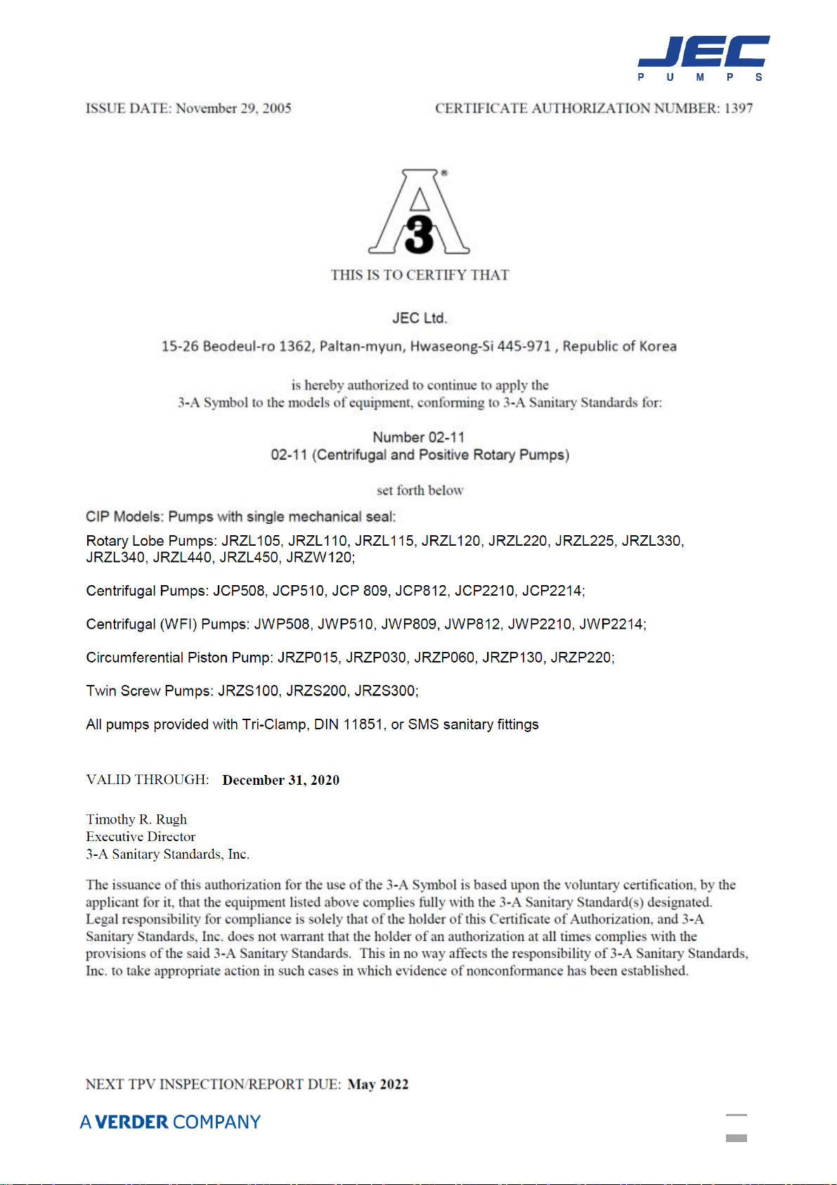
3-A (3-A Sanitary Standards, Inc.) …………………………………………………………………………………
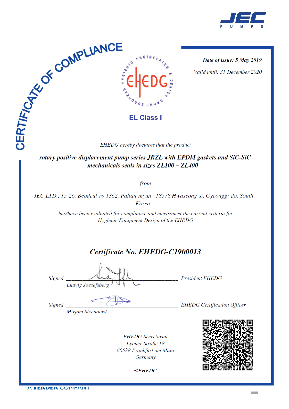
EHEDG (European Hygienic Engineering & Design group) ………………………………………………
DOCs
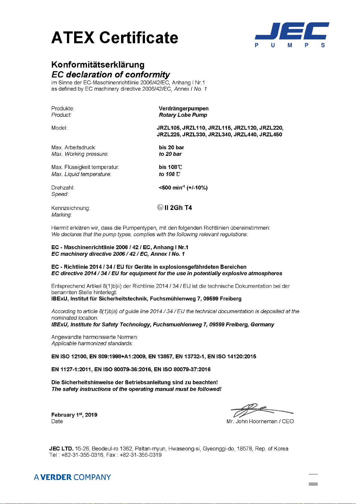
ATEX (European Explosion Proof Certificate) ……………………………………………………………………
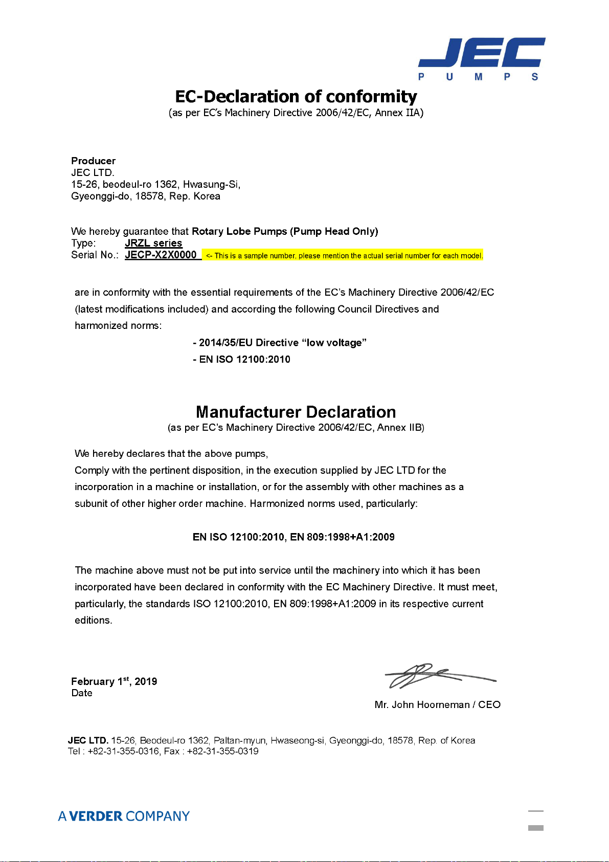
CE (Declaration Of Conformity) ………………………………………………………………………………………
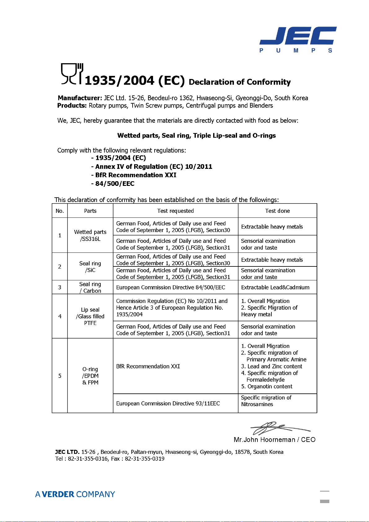
1935/2004 (EC) ……………………………………………………………………………………………………………
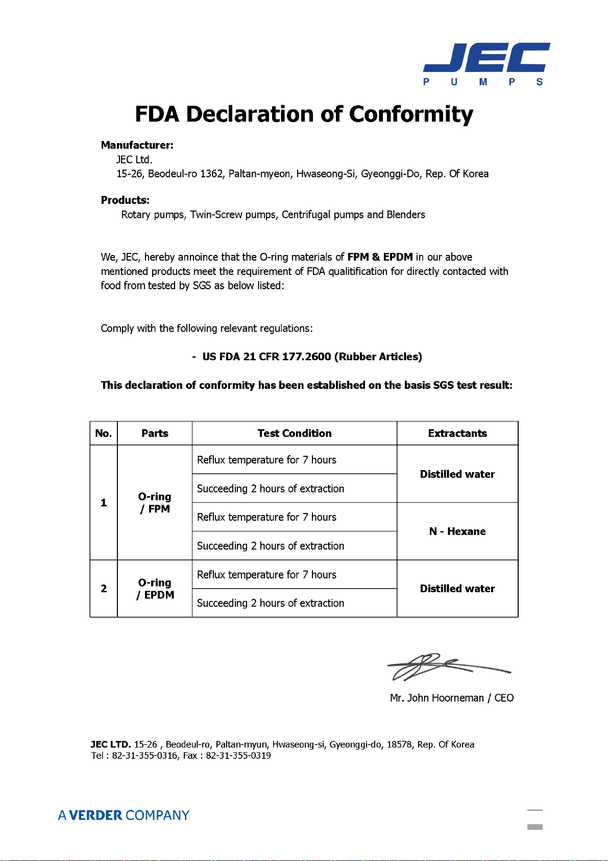
FDA ……………………………………………………………………………………………………………………………
WARRANTY
WARRANTY …………………………………………………………………………………………………………………
SAFETY
DO’S and DON’TS …………………………………………………………………………………………………………
INSTALLATION
Installation …………………………………………………………………………………………………………………
Start Up ………………………………………………………………………………………………………………………
CHECK PUMP ROTATION
Principle of operation ……………………………………………………………………………………………………
Direction of rotation ……………………………………………………………………………………………………
OPERATION
Troubleshooting …………………………………………………………………………………………………………
Cleaning ………………………………………………………………………………………………………………………
MAINTENANCE
Rotor Case Disassembly ………………………………………………………………………………………………
Inspection ……………………………………………………………………………………………………………………
Seal Maintenance …………………………………………………………………………………………………………
Rotor Case Assembly ……………………………………………………………………………………………………
Rotor Clearance ……………………………………………………………………………………………………………
Rotor Timing ………………………………………………………………………………………………………………
Gearbox Maintenance …………………………………………………………………………………………………
Lubrication …………………………………………………………………………………………………………………
TECHNICAL INFORMATION
Technical Data ……………………………………………………………………………………………………………
Dimensional Drawing ……………………………………………………………………………………………………
PARTS LIST
Exploded View & Part List ……………………………………………………………………………………………
2
2
3
4
4
5
6
7
8
9
10
11
12
13
13
14
14
15
16
17
18
19
22
23
24
26
30
31
32
33
2
GENERAL
GENERAL INFORMATION
Thank you for your purchasing JEC products!
This manual is a part of the JRZL series Rotary Lobe Pumps describes safe and appropriate
operation during operating and in all life cycles.
This contains instructions for installation, operation, disassembly and assembly, maintenance
procedures, troubleshooting and a complete parts list for all.
Read and completely understand this manual to learn how to service these pumps prior to
operating or servicing product and observe to pay special attention to the warnings.
This must always be available at the installation location since no liability will be assumed for any
damage or operational malfunctions arising from non-compliance with these operating instructions.
INTENDED USE
The pump is only to be used for the media pumping agreed in the applicable data sheet or
specification. Any other application beyond the intended use or conversion of the pump without
written agreement with the manufacturer shall be deemed to be not in accordance with the
intended use.
The pump may only be started up for the first time if it has been ensured that all safety devices
are completely fitted and functional.
If any areas are subject to have the risk of explosion, the relevant explosion-proof designed pumps
to be used.
Intended use also covers compliance with the conditions of operation, servicing and maintenance
specified by the manufacturer.
The pump is only to be put into operation filled with medium to be pumped.
Before starting up ensure that;
- Open the valves on the suction side completely to avoid cavitation and,
- Open the valves on the discharge side open completely to avoid exceeding the permitted
differential pressure of the pump
- Discharge-side safety measures should be done (e.g. safety valve) to protect the pump from
non-permitted excess pressure
- Protection against contact for hot, cold and moving parts must not be removed during
operation
3
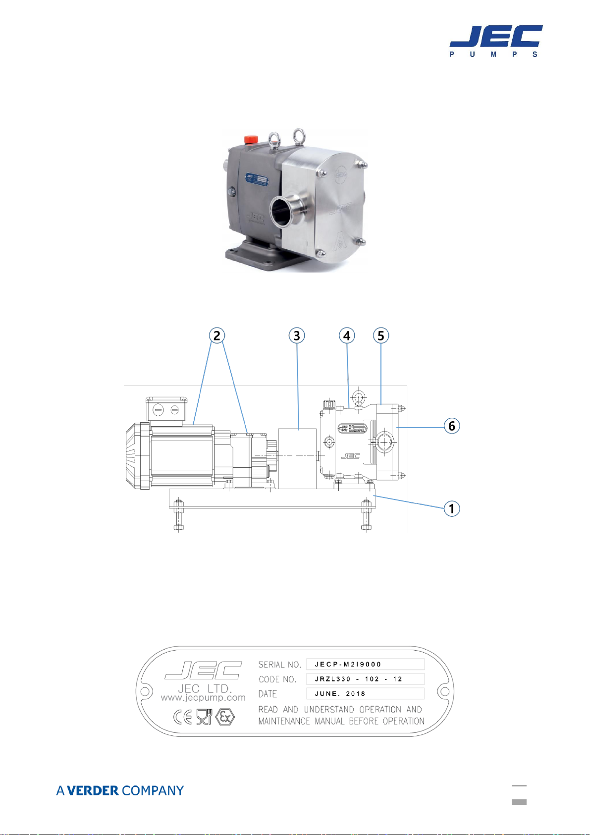
CONSTRUCTION
JRZL series Rotary Lobe Pumps can be ordered with bare shaft, i.e. pumps without motor or
common bed.
Or, ordered as a complete unit with drive motor, coupling & guard, common bed (or trolley) and
layout described as below.
Example Layout of pumps with complete unit
①Common bed, ②Drive unit, ③Coupling & coupling guard,
④Gearbox, ⑤Rotor case with inlet & outlet ports, ⑥Front cover
The nameplate is fixed on the gearbox shown an example as below.
4
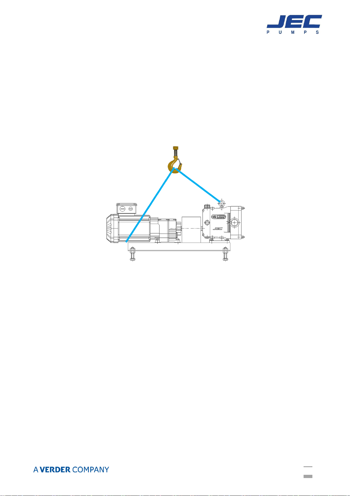
PACKAGING & TRANSPORT
JRZL series are shipped in non-returnable wooden packaging.
Unpack the pump/unit upon delivery and inspect it for visible transport damage.
Any damage occurred during the transporting has to be immediately reported to the transport
agent after receipt of the consignment. Do not put the damaged products into operation.
The pumps need to be transported and secured with care to ensure no damage caused. Lifting
equipment (hoist) and load securing straps must be placed with sufficient load capacity.
Make sure you sent the pump down on a sufficient table, horizontal surface.
Below picture of complete unit with drive & common bed is shown for the example.
STORAGE
If the pumps need to be stored temporarily, it should be sufficiently preserved under normal
environmental conditions and must not be exposed to the weather for any significant period of
time.
Heed below measures when required to be stored longer period.
1. Protect pumps with dust, dirt, water or any other harmful environmental factors. Coat all
non-painted surfaces with acid-free and resin-free grease.
2. Do not grease stainless steel parts and non-metallic parts.
3. Cover all openings of pressure and suction ports.
4. Drain water when using it as flushing/quench medium for shaft seal.
5
6
7
8
9
10

11
WARRANTY
Terms, Warranty Provisions, Notice of Claims and Limitation of Liability
All terms & conditions and prices of sale are based on the applicable JEC price list at the time an
order from Customer is received by JEC and are subject to change without notice. No assignment
of the purchaser’s rights may be made without consent of JEC.
JEC warrants its Product from defects in materials and workmanship for a period of one (1) year
from the shipment date, providing it has been used as recommended and in accordance with
recognized piping practice, and providing it has not been worn out due to severe service, normal
tea and wear or subjected to accident, misuse or improper maintenance. This warranty extends
only to the original Buyer.
This warranty is expressly in lieu of any other warranties expressed or implied, including but not
limited to any implied warranty of merchantability or fitness for a particular purpose.
All claims must be in writing and must be mailed or delivered by purchaser within thirty (30) days
after purchaser learns of the facts upon which such claim is based. Any claim not made in writing
and within the time period specified above shall be deemed waived.
Purchaser’s sole and exclusive remedy and JEC Ltd.’s maximum liability for claims arising
hereunder or for negligence for any and all losses and damages resulting from any cause shall be
either the repair or replacement of defective components or pumps verified by JEC.
In no event, including in the case of a claim for negligence, shall JEC Ltd. be liable for incidental or
consequential damages including loss of profits.
No person, including any representative, employee or agent of JEC, is authorized to assume on
behalf of JEC, any liability or responsibility in addition to or different from that described in this
provision. Any and all representations, promises, warranties or statements that are in addition to
or different from the terms of this provision are of no force or effects.
RECEIVING INSPECTION
Ports are rubber capped at the factory to keep out foreign objects. If covers are missing or
damaged, a thorough inspection of fluid head, by removing pump cover, is recommended. Be sure
pumping head is clean and free of foreign material before rotating shaft.
LOSS OR DAMAGE
If your pump has been lost or damaged in transit, immediately file a claim at once with the
delivering carrier and ask for an Inspector to call. The carrier has signed the Bill of Lading
acknowledging that the shipment has been received from us in good condition.
We will of course assist you in every way in collecting claims for loss, or damage, however, we are
not responsible for the collection of claims or replacement of material.
12
SAFETY
DO’S & DON’TS
DO read and understand these instructions before installing or using the pump.
DO use JEC spare parts when replacing a component of the pump.
DO NOT service the pump while it is running.
DO NOT place the pump in an application where the service ratings are exceeded.
DO NOT modify the pump. Modifying the pump creates unsafe conditions and voids all
warranties.
SAFETY PRECAUTIONS WHEN INSTALLING PUMP
DO use an authorized electrician when connecting the pump.
DO observe the mechanical limits of the pump (refer to the pump performance sheet).
DO install a throttling valve in the discharge line.
DO earth the base plate of pump to avoid the potential build up of static electricity.
DO NOT install a throttling valve in the suction line.
SAFETY PRECAUTIONS WHEN OPERATING PUMP
DO only qualified personnel should operate this pump.
DO NOT start the pump until all personnel are clear.
DO NOT touch the pump or the lines when pumping hot fluids or when performing Clean In
Place (CIP) procedures.
DO NOT run the pump with BOTH the suction inlet and discharge outlet blocked. Running the
pump with the inlet the blocked will cause serious damage to the pump.
DO NOT check pump rotation with liquid in the pump.
DO NOT run the pump with the front cover removed. The rotors and rotor case could be
damaged or may cause severe injury.
DO NOT operate the pump with removed the safety guard or shroud.
SAFATY PRECAUTIONS WHEN SERVICING PUMP
DO ensure the pump is cool to touch before performing service.
DO relieve all pressure and drain all fluids from pump and connected piping before performing
service.
DO ENSURE POWER TO THE UNIT HAS BEEN UNPLUGGED PRIOR TO PERFORMING
ANY PUMP MAINTENANCE OR CLEANING.
DO exercise caution and wear protective clothing when using lye or acid for cleaning.

13
INSTALLATION
INSTALLATION
1. Mounting surface should be flat and level.
2. Ensure at least 0.5m clearance around the pump.
3. Normally, pump and drive unit are configured with common bed. If you want other way,
feel free to contact JEC.
4. To check the direction of rotor’s rotation, start and stop the motor for a short time.
5. Before connecting pipelines, check the location of suction and discharge.
6. Ensure the pipelines are connecting correctly and tightly.
7. The suction line should be kept as short as possible and present minimum friction loss.
8. To check working condition correctly, we recommend installing flow open valve and
pressure gauge at discharge line.
9. Suction and discharge lines must be fully supported and installed so that no expansion or
shock forces act on the pump which could lead to distortion.
10. Ensure sufficient clearance around the motor and pump.
START UP
1. Before connecting the suction and discharge pipe work the entire system must be
thoroughly cleaned to prevent damage from welding, grinding and other residues.
2. Before starting, bump the motor to check if the motor fan is rotating clockwise or
counterclockwise when seen from the motor back. If the motor fan cannot be seen, look
through the pump case adaptor after takeoff motor shroud. (Bump means to momentarily
apply power to the motor and then immediately remove power).
3. Direction of rotating must only be checked with a completely filed system. Where double
mechanical shaft seals are installed the flush supply must be operational. Any dry running
will result in seal damage.
4. The motor rating plate should be checked to ensure that it is in accordance with the
available electrical supply. It is essential that the full load current is not exceeded to
prevent motor overload.
5. Before start up any safety guards required by local statutory regulations should be fitted.
Pay attention to circumstances that could indicate pump cavitation;
1. Low pressure in the suction line due to bad suction conditions.
2. Air in the suction inlet line.
3. Pumping temperature is too high.
4. Pump is oversized.

14
CHECK PUMP ROTATION
PRINCIPLE OF OPERATION
-The pumps are of the positive displacement rotary type with lobed rotors. The volume at
the inlet increases when the rotors rotate and the product is drawn into the pump. It is
then transported in the space between the lobes and the periphery of the pump housing to
the discharge side. The volume between the rotors is reduced here and the product is
forced out through the outlet.
DIRECTION OF ROTATION
-The direction of flow is dictated by the direction of rotation of the drive shaft. Reversing
the direction of rotation will reverse the flow direction. Top and bottom shaft drive.

15
OPERATION
TROUBLESHOOTING
Problem
Cause
Solution
Pump not turning
Interruption of electrical power.
Key sheared or missing.
Coupler or belts are not connected.
Pump shaft or gears sheared.
Wrong rotation.
Relief valve not properly adjusted.
Reset circuit breaker, check fuses.
Replace.
Replace or adjust.
Replace.
Reverse.
Adjust valve.
Pump not priming
Valve closed in suction lines.
Suction line clogged or restricted.
Air leak in connections or seal.
Pump speed too slow.
Suction line does not remain flooded.
Air lock.
Excessive clearances in pump.
Net inlet pressure low.
Open valve.
Clear suction line.
Repair leak.
Increase sped.
Install foot valve.
Bleed suction line.
Replace out of tolerance parts
Increase suction pressure
Insufficient flow
Speed too low.
Air leak.
Adjust speed as required.
Repair leak.
Noisy operation
Cavitation.
Viscous product.
High vapor pressure, high temp.
Leaks in piping or pump.
Dissolved gas in product.
Mechanical noise.
Excessive weight from piping,
Pump body distorted.
Excessive discharge pressure.
Worn bearing.
Worn gears.
Rotor-to-rotor contact.
Increase net inlet pressure.
Slow pump, reduce product.
Reduce temperature.
Repair leaks.
Reduce discharge pressure.
Check tolerances.
Support piping.
Check align and level
Reduce discharge pressure.
Replace bearing.
Replace gears
Time rotors, replace twisted shafts,
replace worn gears.
Pump overloads
Viscosity of product higher than
expected.
Higher pressure than expected.
Reduce pump speed, increase
piping size,
Reduce pump speed, increase
pipe size,
Play between gears
Worn gear teeth.
Gear loose on shaft.
Replace gear.
Inspect gear key, keyway and shaft.
If all are undamaged, retighten the
gear retaining nut.
Check for backlash.
If assistance is required, please contact your local sales office with the following information:
1. Operating conditions.
2. Accurate description of default.
3. Model of pump and serial number.
4. If possible installations sketch of pump system.
16
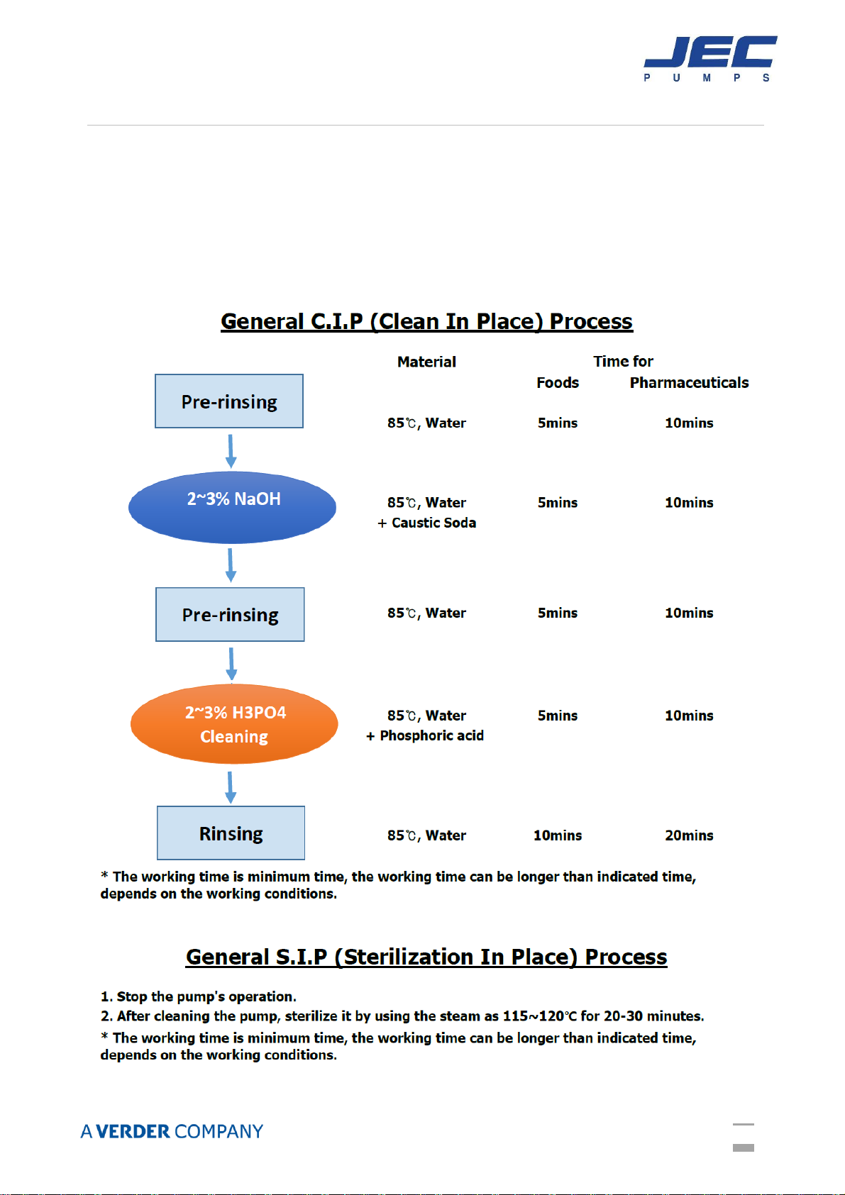
CLEANING
1. Before cleaning the pump, wear rubber gloves and protective glasses.
2. While CIP and SIP process, do not touch the pump and pipelines.
3. Ensure velocity rate of CIP solutions is adequate to clean entire circuit. For most
applications a velocity of 1.52 m/sec is sufficient. For the CIP solution to achieve the
proper velocity, the pump drive must have enough speed range and horsepower. The
required inlet pressure also must be satisfied. If the pump does not supply enough CIP
solution velocity, a separate CIP supply pump with an installed bypass may be used.
4. Refer to the below CIP and SIP process.
17
MAINTENANCE
ROTOR CASE DISASSEMBLY
Prior to removal of pump, the shut-off valves in the suction and discharge pipe work must be
closed. If there is any risk that product may be hardened, crystallized or frozen in the pump it
should be thoroughly drained and cleaned immediately after use. Similar attention must be
applied to the seal flushing system. Remove power before servicing to prevent from any
unintended start of the pump by an authorized electrician.
Reference numbers are listed in the ‘PARTS LIST’refer to the exploded view on pages 26-30.
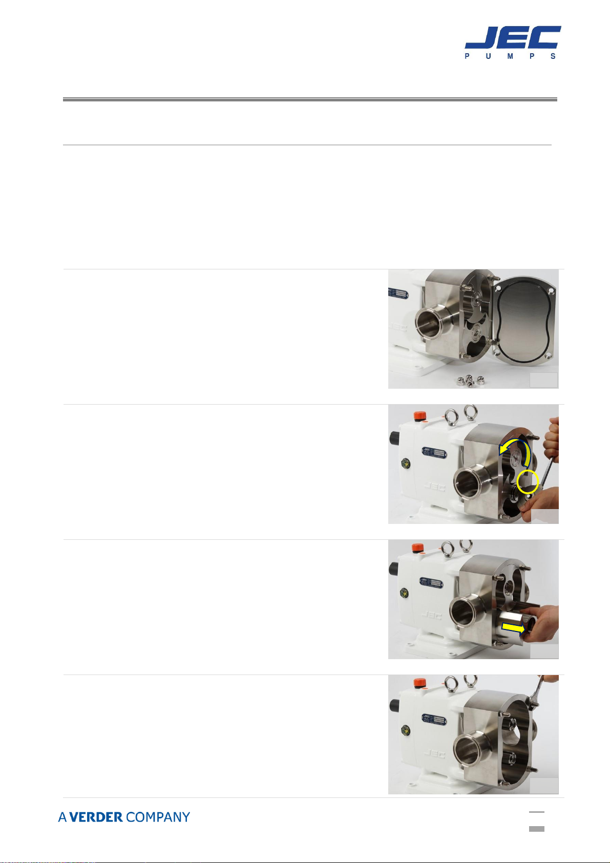
Start by removing the front cover after removing the cap nuts
using the appropriate wrench from the cover. During this
process, place all parts on a clean, protected surface with
finished surfaces and seal faces facing up. If it is stuck, tap
the cover off using a soft mallet.
And then, remove the cover O-ring and inspect.
Remove rotor bolts using the special tool supplied with pump
or appropriate size wrench. To remove rotor bolts, place the
plastic bar between rotors to keep the rotors from moving as
shown in Figure 2.
Turn in the drive rotor bolt to the counter-clockwise direction
and extract rotor bolts and spring washers.
Rotors can be removed from rotor case by pulling straight.
It is important to be cautious with the rotors so that they are
not damaged.
Remove hexa-nuts on the four stud bolts securing the rotor
case to the gearbox.
Fig. 1
Fig. 2
Fig. 3
Fig. 4
Fig. 1
18
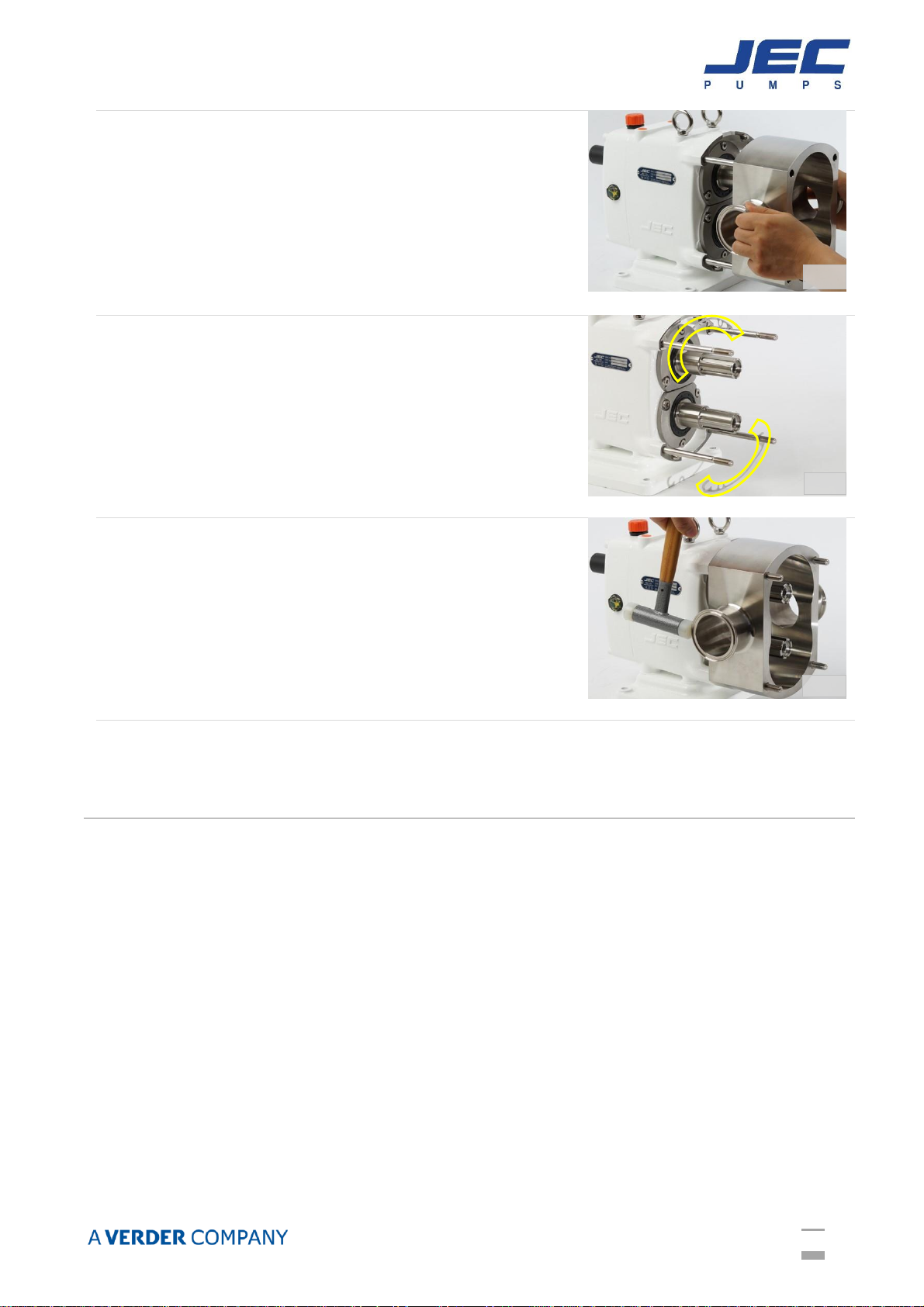
After pulling out both rotors, rotor case can be separated by
sliding along the stud bolt and pulling out from the Gearbox.
Inspect the rotor case for wear, clean and continue to seal
maintenance, if needed.
In this time, handle and place carefully to keep the right track
of position of the top & bottom shim(s) which shafts are
associated with, to avoid lost, damaged or misalignment
They are installed accordingly at the factory for that
particular body.
If it is stuck tight, tap alternately on the back of the inlet and
outlet ports using soft mallet as shown in Figure 7.
INSPECTION
While performing standard maintenance or cleaning, check for signs of damage or extreme wear.
A simple inspection may show signs of a problem long before it becomes serious. Detection of
such problems can avoid costly repairs and reduce down time.
1. Inspect O-rings and seals for re-use. Worn O-rings and seals should be replaced.
2. Inspect seal faces for chipping, scratches or cracks. Replace any seal faces if damaged.
3. Inspect shaft shoulder matched to rotors and other metal parts worn or damaged.
4. Inspect rotor galling sign among the rotor case, front cover and rotors. It must be
removed or replaced.
5. Inspect bur of the rotor bolt groove. It must be removed or replaced.
Fig. 5
Fig. 6
Fig. 7
19
SEAL MAINTENANCE
JRZL series is designed by ‘Front Loading Seal’ that the mechanical seal system can be changed
or replaced without removing rotor case.
Check & inspect all components of seal replacement kit carefully whether there is any damage or
defect before installing. If any chipping, crack or scratch found during inspection, do not reuse
them and replace the damaged one.
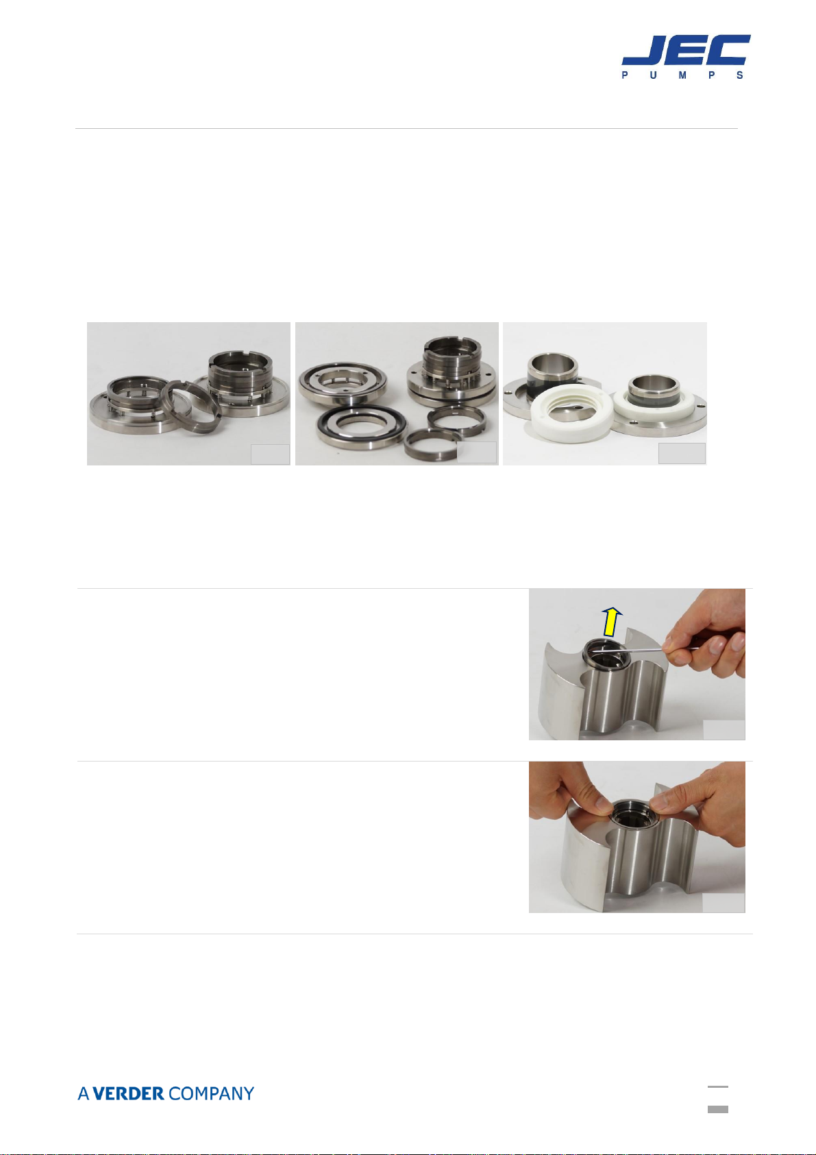
Below shows the Single mechanical seal (Figure 8), Double mechanical seal (Figure 9) and
PTFE Triple lip seal (Figure 10).
If replacement for the seal ring only required, you can easily dismantle and pull it off
from rotor case just after removing rotors without dismantling for the rotor case
thanks to ‘Front loading seal design’. And put the new one and push into rotor case.
The seal ring can be easily removed from rotor by using a small
screw driver ( ) or pin as shown in Figure 11. This is common
for the Single mechanical and Double mechanical seal.
Put rotor face down on the table and pull out the seal ring from
rotor.
Put the replacing NEW seal ring on the rotor and push
downward and inserted into the rotor in Figure 12.
Fig. 8
Fig. 9
Fig. 10
Fig. 11
Fig. 12
This manual suits for next models
5
Table of contents
Other JEC Pumps Water Pump manuals


Popular Water Pump manuals by other brands

Becker
Becker VX 4.16 operating instructions

Warren rupp
Warren rupp SANDPIPER HP10 Service & operating manual

ASC
ASC SP010 instructions

AC Infinity
AC Infinity AC-AUS21 user manual

Cole Parmer
Cole Parmer Barnant Masterflex 07534-04 operating instructions

LEYBOLD
LEYBOLD TRIVAC D 16 B-DOT operating instructions


Seko
Seko MSA Series installation manual

K2 Pumps
K2 Pumps SPA02501VDK owner's manual

NES
NES NBE Series Operation & maintenance manual

Smeg
Smeg PAD Installation instruction sheet

Wright Flow Technologies
Wright Flow Technologies TR-IS Series Installation, operation and maintenance manual

Hayward
Hayward LifeStar VS owner's manual