Seko MSA Series User manual

SPR0136037 Rev. 1.5
EN
DE
ES
FR
IT
MECHANICAL DIAPHRAGM
MSA/MSV SERIES
INSTALLATION MANUAL
HANDBUCH
MANUAL DE INSTALACION
MANUEL D’INSTALLATION
MANUALE D’INSTALLAZIONE

SPR0136037 Rev. 1.5

SPR0136037 Rev. 1.5
Instruction Manual for Mechanical Diaphragm
MSA/MSV series

SPR0136037 Rev. 1.5
Before installation and use of this device, please read carefully this instructional manual, standard
constructor is not responsible for any loss caused by not following instructions contained. Standard
constructor remains the right to alter any contents without notice in advance.
Warranty and scope
[1] Upon receiving the pump, please check if the products are damaged, accessories and stand-by
are contact, if any damage happens during shipment, please immediately contact us.
[2] The warranty period is one and half a year starting from the date of delivery from our factory.
[3] During warranty period, under normal use, if some parts fall off or have defect due to improper
design and manufacturing, standard constructor will repair or replace those parts free of charge.
[4] The user must pay relevant charges in the following conditions:
The warranty is expired; the pump is wrongly used or stored; Customers use bad quality s
pare parts that are produced by manufacturers not recommended by standard constructor.
Any damage that is caused by maintenance done by workers not from standard constructor or not
designated by standard constructor.
Any damage that is caused by fire, earthquake or other natural disasters;
[5] Standard constructor is not responsible for products that are made from materials designated
by customers in accordance with standards of customers.
[6] Standard constructor is not responsible for any corruption to products caused by fluid chemical
reaction or directly by fluid to be dosed. The model recommendation from standard constructor is
only for suggestion and standard constructor is responsible for any results.
[7] Trouble or damage reason should be jointly confirmed by customer and our service engineer
after detailed discussion.
[8] Standard constructor is not responsible for fees incurred by disasters during pump operation.
Maintenance
During operation, if any abnormal situation is found, please immediately stop operation and check
if pump part fails to work (please refer to the instruction manual)
[1] Please contact Standard constructor or our authorized distributor for maintenance.
[2] Please read carefully the instruction manual to check the product before calling us or our
distributor for maintenance.
[3] If the pump needs to be returned to Standard constructor, please fill Service Sheet for our
reference and facilitate maintenance:
1. Model and series number
2. Ambient environment and service life
3. Details of trouble
3. Before returning pump to standard constructor, please make sure that residues remained in the
pump chamber are thoroughly cleaned.

SPR0136037 Rev. 1.5
Contents
1. Overview
1.1 Application and product identification
1.2 Operational principle of Mechanical Diaphragm pump
1.3 Adjustment of Stroke length
2. Installation
2.1 Installation dimension
2.2 Instructions for installation
2.3 Suction line
2.4 Discharge line
3. Start-up
4. Maintenance
4.1 Instruction for oil-filling
4.2 Sketch for pump head disassembly and installation
4.3 Instructions for motor operation
4.4 Notes
4.5 Recommended parts
5. Trouble shooting
6. Handling and storage
6.1 Handling
6.2 Storage
SPR0136037 Rev. 1.5
1
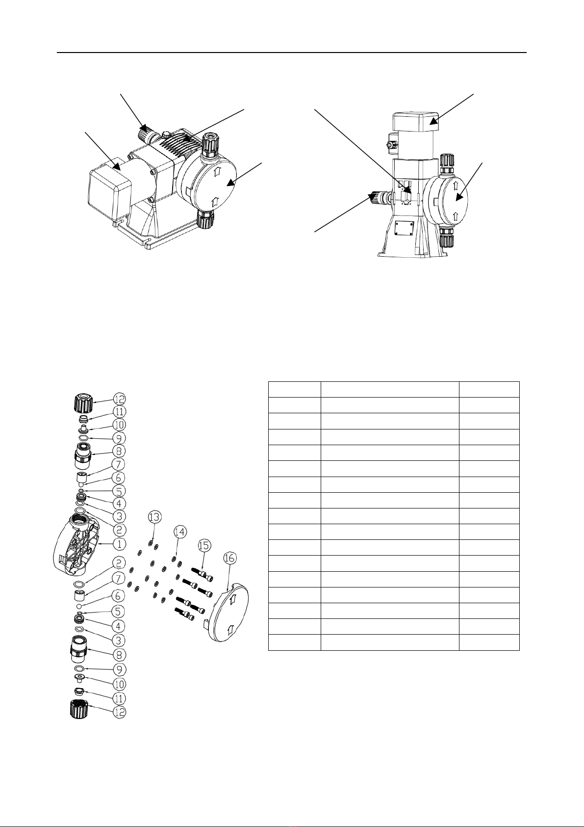
Structure of MSA/MSV series
Disassembly sketch of pump head
Table 1
PVDF pump head (standard)
Number
Description
Quantity
1
Pump head
1
2
Seal D18,72X2,62
2
3
Seal 14,48X2,69
2
4
Ball seat
2
5
Seal 7,65X1,78
2
6
Ball
2
7
Ball cage
2
8
Valve body
2
9
Seal 12,37 X T 2,62
2
10
Gasket
2
11
Clamp
2
12
Connecting nut PVDF
2
13
Gasket for M6 screw
8
14
Spring pad for M6 screw
8
15
M6x25 Hexagon screw
8
16
Cover for pump head
1
Adjustment knob of
stroke length
Adjustment knob of stroke length
Mechanism
Pump head
Motor
Motor
Pump head
SPR0136037 Rev. 1.5
2
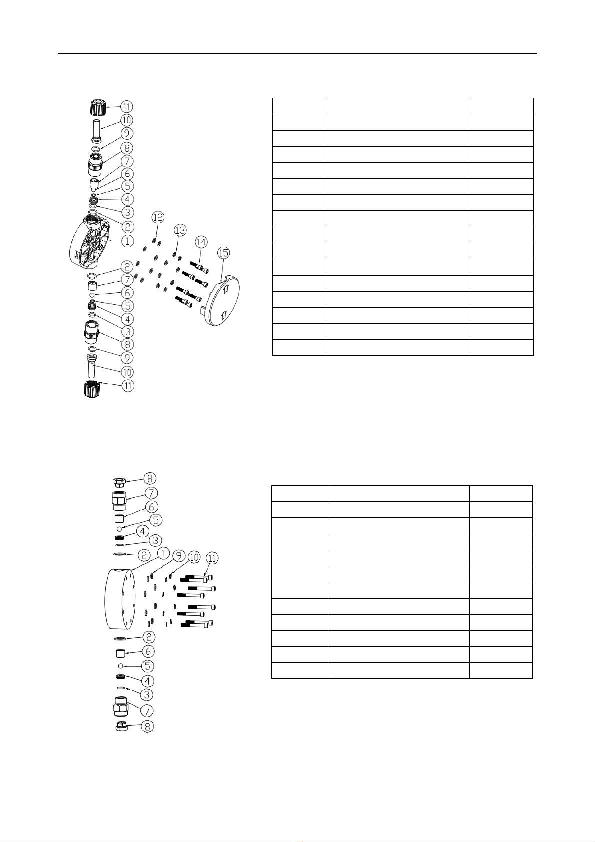
Table 2
PVDF pump head(with DN15 connector( number 10 and 11)
additional cost will be
charged)
Number
Description
Quantity
1
Pump head
1
2
Seal D18,72X2,62
2
3
Seal14,48X2,69
2
4
Ball seat
2
5
Seal7,65X1,78
2
6
Ball
2
7
Ball cage
2
8
Valve body
2
9
Seal 12,37 X T 2,62
2
10
Gasket
2
11
Connecting nut PVDF
2
12
Gasket for M6 screw
8
13
Spring pad for M6 screw
8
14
M6x25 Hexagon screw
8
15
Cover for pump head
1
Table 3
SS316L pump head
Number
Description
Quantity
1
Pump head
1
2
Ball
2
3
Ball cage
2
4
Ball seat
2
5
Valve body
2
6
Seal D12,42XT1,78
2
7
Seal D18,72X2,62
2
8
Valve cap
2
9
Washer for M6
8
10
Spring washer for M6
8
11
Screw M6x50
8

SPR0136037 Rev. 1.5
3
Table 4
Pump head connection with pipeline
Number
Description
Quantity
1
Injection point
1
2
Injection connector
1
3
Seal
2
4
Gasket
2
5
Tube clamp
2
6
Ring nut
4
7
Discharge tube
1
8
Discharge valve
1
9
Pump head
1
10
Suction valve
1
11
Suction tube
1
12
Foot filter
1
Disassembly sketch of mechanism

SPR0136037 Rev. 1.5
4
Number
Description
Quantity
1
Case for DOSY
1
2
Waterproof seal
1
3
Lateral cover
1
4
Screw for lateral cover
4
5
Propulsion shaft
1
6
Oiless bearing
1
7
Spring
1
8
Directional flange for propulsion shaft
1
9
Oil seal
1
10
Screw for directional flange
4
11
Propulsion board for membrane
1
12
Membrane
1
13
Small bearing for fixing eccentric shaft
1
14
Snap spring
3
15
Propulsion bearing for eccentric shaft
2
16
Eccentric shaft
1
17
Big bearing for fixing eccentric shaft
1
18
Fixing board for eccentric shaft bearing
1
19
Fixing screw
2
20
Gasket between motor and pump body
1
21
Motor
1
22
Base
1
23
Label
1
24
Adjustment rod
1
25
Seal for adjustment rod
1
26
Knob for adjustment rod
1
27
Graduation label
1
28
Protection ring for graduation label
1
29
Black cover for adjustment rod
1
30
Locking screw for adjustment rod
1

SPR0136037 Rev. 1.5
5
1. Overview
The metering pump is a reciprocating positive displacement pump; basic components are: the
motor, the gearbox, the mechanism, the stroke length adjustment and the liquid end (pump head)
Safety instruction
WARNING
Exceeding the maximum allowed operating pressure must be prevented
(e.g. by using a pressure relief valve)
Before starting to work on the metering pump verify carefully the following:
- The drive is disconnected from the power source
- Parts such as pump head and piping are depressurized
- Parts in contact with aggressive substances are washed before handling
- Personnel protection is carried out according to local regulations
1.1 Application and product identification
Metering pump is a process component capable to transfer defined volumes of liquid with high
accuracy; moreover it is possible to vary the flow rate by acting on integral devices.
To ob ta in th e be st pe rf o rm a n ce s, se le ct th e p um p co ns id e ri ng th e du ty re qu ire d an d th e
compatibility of the construction materials of the contact parts.
Before using a pump for a duty different from the original one, please contact us
for information.
Actual dimension of product identification
53x35mm
1. Model
2. Reference
3. Series number
4. Max pressure
5. Max flow rate
6. CE certificate
1.2 Operational principle of mechanical diaphragm pump
Mechanism is the device that permits to transform the electric motor rotary movement into
reciprocating movement by gearbox. The reciprocating movement draws membrane, making
the volume of pump chamber change to push the ball up and down to form vacuum adso
rption and squeezing for fluid transfer. The adjustment of flow rate is realized by regulating
the stroke length.

SPR0136037 Rev. 1.5
6
The operational principle is illustrated below:
1) As the membrane is drew back, the ball of discharge
valve drops on and cling to the valve seat , the ball of
suction valve is uplifted by vacuum formed between
membrane and pump head,correspondingly, the fluid is
also suctioned.
2
As the membrane is drew forward, the ball of suction
valve clings to valve seat ,so, the fluid can not pass
through, on the contrary, the ball of discharge valve is
uplifted by membrane’s forward movement.
To obtain high accuracy performances pump must
operate at ideal conditions: constant speed, pressure,
viscosity.
1.3 Adjustment of the stroke length
The adjustment of stroke length is realized by changing the stroke of membrane, and the
adjustment can only be done during pump operation.
MSA/MSV
The variation from 0 to 100% of the maximum flow rate is obtained by rotating the
adjustment knob counter clockwise; each revolution of the adjustment knob corresponds
to a variation of 1/4 of the maximum capacity. After adjustment, you need to lock the stroke
length.

SPR0136037 Rev. 1.5
7
2. Installation
2.1 Installation dimension
2.2 Safety precautions
To successfully install and use our products, please make sure you follow instructions contained in
6.1 and the following precautions:
1) don’t work alone
2) connect motor to grounding
3) When working on the pump verifies that electric motor or servomotor is not connected to
mains.
4) using electric tools in hazardous areas, pay attention to special regulations

SPR0136037 Rev. 1.5
8
5) keep available a first aid kit
6) observe local law safety regulations
7) Foundation height should be so as to facilitate maintenance operation, handling, oil refill and
drain, easy disassembling of pump head
8) Install the pump free of strain on its base, pump head connections and foundation
Precautions for electrical connection:
1) Electric motors and electrical components should be connected in accordance with local
regulations and by qualified personnel only.
2) Install overload protection or temperature sensor.
3) Check voltage, frequency, motor speed and power.
4) In hazardous areas special regulations must be applied.
For a good operation, the correct installation of the pump is fundamental:
Before carrying out hydraulic connections, make sure that the inside of pipes, tanks, etc. have
been thoroughly cleaned/washed. However we recommend the installation of a temporary filter
near to suction nozzle in order to stop plant residues and slags.
Connect pipes avoiding excessively stretching nozzles, or can install a pulse damper.
Install pipes correctly sized for the maximum flow rate of the pump, avoid necks and tortuosity
where air or gas could be entrapped.
Warning:
To prevent serious damages
the suction and discharge lines must be properly designed,
sized and connected to the pump.
2.3 Suction line
Install pipe as short as possible and avoid tortuous paths. The negative pressure situation (suction
uplift) should be avoided, because it will affect accuracy of metering. If the temperature of fluid to
be dosed reaches the boiling point, the enough suction head should be provided to prevent the
fluid from entering suction end during suction line and vaporizing.
The pipe diameter should be decided
in accordance with instantaneous ma
x flow rate (figure left), and the pipe
diameter should be equal to 1.5 the
diameters of the pump nozzles.
In case the pump needs to dose fluid with high viscosity, in order to reduce the loss of fluid, the
diameter of discharge tube must be 4 times as same as that of pump suction nozzle. If you can not
identify the dimension, please contact Standard constructor.
In order to prevent the impurities, do not close the tube to bottom of chemical tank. The suction line
must be airproof to ensure precise flow rate.

SPR0136037 Rev. 1.5
9
2.4 Discharge line
The discharge pressure should be larger than the max rated working pressure of pump.
It is very important to prevent the air entering into the discharge line.
The flow rate can be controlled only when the discharge pressure is larger than the suction
pressure.
Please observe the following instructions when pumping liquids that tend to crystallize or
suspensions that tend to sediment:
Keep suspension correctly agitated in order to prevent sedimentation
Avoid installation of vertical lines over the pump discharge nozzle
Before stopping the pump start a washing cycle of the pump and pipes
Designing suction and discharge lines should permit complete emptying
3. Start-up
Connect the motor to power supply.
Check the direction of rotation of the electric motor; an arrow on the electric motor shows the
correct direction of rotation
The electric motor should be connected by qualified personnel only!
WARNING:
Don’t start the pump with the suction and/or discharge check valves closed
Don’t close check valves while the pump is in operation
Before starting the pump check the following points:
• Check mechanism for the correct oil filling
• Check metering pump for overpressure protection (pressure relief valve installation)
• Verify that all hydraulic connections are correctly tight
• Position adjustment knob at “zero” flow rate
• Start the pump without discharge pressure and increase progressively the flow rate up to 100%
• Check if there is bubble in the pump chamber.
WARNING 1
DON’T EXCEED THE MAXIMUM PERFORMANCE STENCILLED ON THE PUMP LABEL, If no
pressure gauge is fitted on the plant, the installation of a temporary pressure gauge is
recommended in order to check that the actual pressure at the start-up doesn’t exceed the
maximum allowable pressure.
WARNING 2
If the pumped liquid is toxic, poisonous, aggressive, flammable or for any reason
dangerous, use particular care avoiding accidental leakages through gaskets or pipes
during start-up or maintenance operations.
Moreover
follow all the recommendations of the manufacturer for handling and the local
laws relevant to safety during handling and disposal of dangerous substances.
SPR0136037 Rev. 1.5
10
4. Maintenance
4.1 Instructions for oil-filling
Attention
The lubrication grease is filled as shipped from our factory.
Replace oil after 1500 operation hours and afterwards every 4000 hour
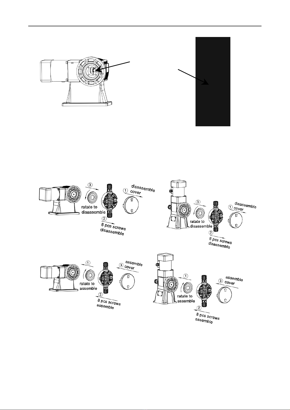
4.2 Disassembly and installation of pump head
1) Disassembly
2) Assembly
Attentions
1. Before disassembling the diaphragm, please position the knob at “ Zero” flow rate
2. The tightening torque for diaphragm is 4 N/m
3. After installation of diaphragm, the knob must be positioned at “ 100%” flow rate and
then install the pump head
Internal bearing and
adjustment rod shall
be lubricated

SPR0136037 Rev. 1.5
11
4.3 Instructions for motor operation
1. The ambient environment for motor is below 1000m, with temperature from -15°C to 40°C
2. The user should provide the power supply with stable voltage( single phase or
three-phase) corresponding to motor, especially for three-phase, every phase must be same
without failure, otherwise, the motor will be burned.
3. Wire connection
1) Connection for 110V and 220V: the yellow and green
wires are connected to the earth, and the black and red
wires are connected to the live line and the neutral line. The
rotation of motor has no effect on operation of pump.
2) Connection for 380V: the yellow and green wires are
connected to the earth, and the other three wires are
connected to the power supply wire. The rotation of motor
has no effect on operation of pump.
Connecting the motor to power supply, the user should
pay more attention to safetyand reliability of connection, no failure and wrong connection i
s allowed( especially for three-phase)
Virtual connection: the wire screw is not tightened or dropped.
Phase-losing connection: two phases are connection, the remaining phase is disconnected.
4. The motor should be installed at the dry place where is waterproof and dustproof with good
ventilation and heat dissipation condition.
5. Under normal working condition, the motor needs to be maintained at least one year, with main
maintenance on external cleaning of motor ( including internal fan cover, fan leaf surface and
surface of external housing ventilated rib), if the working condition is harsh ( outdoor or more dust),
the periodical maintenance time should be shortened( half an year, three month or even shorter)
6. The connecting wire between motor and power supply should be checked yearly for aging. In
terms of motor selection, under rated voltage, the torque should be corresponding to its related
equipment, not exceeding the rated torque; otherwise, the shaft of motor might be broken or
burned.
7. The motor must connect to grounding to avoid creepage, causing injury of person.
8. Handle and store carefully the motor.
9. The gearbox is closely connected to the motor, so the collision with motor can lead to loose
connection between motor and gearbox, which will reduce their life. Make sure good ventilation to
avoid overheating of motor.
10. Some simple solutions for motor troubles
The motor
can not start
but buzz
There is circuit
breaking, which
causes motor to
operate under single
phase condition
(very easy to burn
the motor)
1. Check if the connection between switch and stator
winding is correct
2. Check if the terminal is loose
3. Check if the wire is broken or has virtual connection,
use multimeter to check.
4. Check if starting device is connected correctly.

SPR0136037 Rev. 1.5
12
Low voltage
1.The power supply cable is too thin to burden huge
starting pressure, change into thick cable
2.The motor that should be connected by triangle
connection is wrongly connected by star connection, and
the motor is started with heavy-duty
The motor
temperature
is too high
and is smo
king
The voltage is too
low or with heavy
load; the pump stops
operation or bad
lubrication
1. Measure if the voltage is too low
2. Measure if the current is too big, if exceeding the
rated current, it might be overloaded, so it can
reduce the load
3. Solve the mechanical problem and fill lubrication oil
The motor suffers
from bad ventilation
or insolation
1. Check if the fan leaf is damaged or fixed
2. Check if the fan cover is jammed by dust
3. Remove articles affecting ventilation and heat
dissipation
4. Provide necessary shield for motor
The voltage is too
high or the wire
connection is wrong
1. If the voltage is too high, consider providing stable
power supply
2. The motor that should be done by triangle connection is
wrongly connected by star connection, so the phase
voltage is reduced and light load can be burdened, but for
heavy load, the motor heats and might be burned even.
3. The motor that should be done by star connection is
wrongly connected by triangle connection, so the phase
voltage is increased and immediately stop motor
operation, otherwise, the motor might be burned.
The motor is started
frequently or its
rotation direction is
changed very often
Reduce times of rotation direction change and start-up
Mutual friction
between stator and
rotor
1. The screw of motor cover is loose, forming gap
between cover and housing, the solution is to tighten the
screw
2. The rotor bearing block is too small or the bearing
chamber of motor cover is too big
The fuse is
burn or
tripped
Start under single
phase power supply
Check switch and fuse
There is short circuit
between switch and
motor
Check if there is short circuit between motor terminal and
if there is short circuit on the connecting wire between
motor and power supply
The stator winding is
not earthed or there
is short circuit on the
The motor should be earthed and insulate the short circuit

SPR0136037 Rev. 1.5
13
stator winding
The fuse is too thin
Replace the fuse with the one that corresponds to the rate
current of motor
The
Housing of
motor is
electriferous
The outgoing wire of
motor is broken and
contacts with the
housing
Open the wire box and tape the broken part with insulated
tape
The power supply
wire is broken and
contacts with the
housing
Tap e the p ow er s u p p ly w ire w ith i ns u la te d t ap e
The winding of stator
is aged and is
creepage
The winding of stator is aged and is creepage
The
insulation
resistance
of winding is
low
The working
condition of motor is
harsh, with moisture
and drop into the
motor, damaging the
insulation layer and
causing low
insulation layer
Use the megger to check and dry the stator
The insulation layer
is aged
The stator winding should be redipped for painting and
dried.
4.4 Notes
Before servicing pump or its related equipment verify that all electric connections (power and
control unit) have been disconnected from mainsDepressurize completely pump and pipes and
drain the section in which maintenance is required
Don’t pour in the ambient polluting substances such as pumped chemicals, hydraulic liquid,
lubricating oil, etc.
Before servicing pump or its related equipment, read carefully the technical specification of the
handled fluids with particular respect to the actions that must be done in case of accidental contact
with a dangerous fluid.
As minimum every six months, dismount the pump head as follows:
Disconnect suction and discharge pipes
Drain processed liquid in the pump head and pipes
Unscrew bolts fixing the pump head to mechanism
Dismount suction and discharge valves
SPR0136037 Rev. 1.5
14
4.5 Recommended spare parts
In order to face normal service problems and to avoid possible waste of time, we suggest to keep
in stock a small supply of the following spares:
One membrane
Two sets of plunger packing
One suction valve complete
One discharge valve complete
When ordering spares, please indicate always the model and the serial number of the pump
5. Trouble shooting
Trouble
Possible cause
Solution
Pump can
not work
The check valve is damaged or
polluted by fluid
Clean or replace new check valve
The chemical level in the tank is
too low
Inject more chemical
The discharge tube is jammed
Clean and dredge the tube
Disconnect motor from
power supply
Connect to power supply
The power supply cable
is disconnected
Find the disconnected part and repair
Position the knob at “zero” flow
rate
Readjust the knob
The voltage is not stable, burning
the motor
Measure and rectify the voltage, repair or
replace new motor
Low
flow rate
The chamber and tube remain
gas
Discharge the gas
The suction line is jammed
Clean the suction line
The suction head is too high
Relocate the pump to reduce suction head
The fluid temperature is too high
Cool the liquid
The fluid viscosity is too high
Reduce the viscosity( through heating or
dilution)
The check valve is too dirty
or damaged
Clean or replace check valve
The suction line is incorrectly si
zed
Check the length and diameter of suction line
The stroke length is wrongly
regulated
Check and readjust stroke length
The speed of pump is abnormal
Choose power supply and frequency that
corresponds to that of motor label
Excessively
big flow rate
The discharge pressure is lower
than suction pressure
Install back pressure valve
Wrong stroke length
Check and adjust stroke length

SPR0136037 Rev. 1.5
15
Motor
overheats
The discharge pressure is too
high
Check the setting of pressure relief valve
The discharge line is incorrectly
sized
Check the length and diameter of discharge
line
The power supply does not cor
respond the electronic specificat
ions
Make sure that the power supply
corresponds to motor
Work
with noise
Wrong electrical connections
Check and rectify connections
Lack of lubricant in the mechan
ism/gearbox
Refill with the correct lubricant
Excessive wear of the mechani
sm/gearbox
Overhaul mechanism/gearbox
The pipeline
vibrates
Pipe diameter too small
Enlarge pipe diameter
Pulsation damper out of operation
or too small
Repair or recalculate damper volume
6. Handling and storage
6.1 Handling
Here below is instructions for handling
- Do not sling, pull, push the pump head nozzles or flanges
- Do not sling, pull, push the adjustment knob
6.2 Storage
Precautions
During shipment and storage, the protection against rain, sand, dust, dirty and direct sunlight are
required.
Should the pump be stored for a long time, please store it in a dry and ventilated place.
Important Instruction for MSA/MSV Series
1) Please make sure that this instruction is attached to the pump
2) Make sure that the voltage and frequency is matched. Power supply: 380V/50Hz (or
220V/50Hz, refer to label for details), the motor temperature should be lower than 80 under
normal operation; It is strictly forbidden to operate without liquid for long time (not exceeding 3
minutes)
3) The pump is unable to work at the pressure exceeding its rated pressure (max working
pressure), and its rated pressure value is marked on the label, expressed by bar
(1bar=1kg/cc=10mlift). If the pump works overpressure, it might be damaged.
4) When the chemical to be dosed reacts to water, for example concentrated sulfuric acid, the
chamber must be cleaned and dried (some water drop might be left while testing at our factory)
5) When the adjustment knob is positioned below 100% graduation, the voice from internal
mechanism is relatively big, this is normal, in addition, we suggest you not to position below 30%
graduation.
6) Please make sure that the discharge/ suction line is installed correctly, and the suction line
(suction valve) is installed downward vertically; the discharge line (discharge valve) is installed
upward vertically; the discharge valve does not replace the suction valve each other. Loss of any
This manual suits for next models
1
Table of contents
Languages:
Other Seko Water Pump manuals

Seko
Seko KOMPACT DPT User manual

Seko
Seko KOMPACT AMC 200 User manual

Seko
Seko Tekna Evo TPG series User manual

Seko
Seko PULV User manual

Seko
Seko AKTUA ATR-05S Manual

Seko
Seko KRONOS 50 User manual

Seko
Seko PoolMatch pH User manual

Seko
Seko OPL Mini L Manual

Seko
Seko Maxima MPG User manual

Seko
Seko TDS Series User manual


Popular Water Pump manuals by other brands


Tallas Pumps
Tallas Pumps P1 300 Instruction for installation and maintenance

Westfalia
Westfalia 86 02 57 instruction manual

Wilo
Wilo Atmos GIGA-I Installation and operating instructions

MRC
MRC PP-D-720 Operation manual

Graco
Graco 231169 Instructions-parts list

Wilden
Wilden A2 Original Plastic Series manual