Jedai STAGE PRO SM16 User manual

MIXING CONSOLE
STAGE PRO
SM 24
OPERATING
INSTRUCTIONS
MIXING
CONSOLE
STAGE PRO
SM16
SM24
TRIPAC
8.4.4.2
MAIN OFFICE AND FACRORY
608, Wha San-Ri, I Dong-Myeon, Yong In-City, Kyung Gi-Do, KOREA
TEL : +82-31-335-1311
FAX : +82-31-335-1911

SAFETY INSTRUCTIONS
Read all safety instruction before operating the 4Bus console.
1. INSTALL EQUIPMENT AS FOLLOW CONDITIONS
Install at the place, not bending curved.
Do not install this apparatus in a confined space such as a book case or similar unit.
The apparatus shall not be exposed to dripping or splashing and no object filled with liquids,
such as vases, shall be place on the apparatus.
Locate mixers away from heat source, such as radiators or other device that produce heat.
Do not drop objects or spill liquids into the inside of mixers.
2. KEEP IN MIND THE FOLLOWING WHEN CONNECTING AMPLIFIER
Connect the mixers after reading of O/P manuals.
Connect each connection of mixersperfectly, if not, it maybe Caused hum, damage, electric shock
in case of mis-connecting.
To prevent electric shock, do not open top cover.
Connect the power cord with safety after check of AC power.
Mixers should be serviced by qualified service person.
WORNING: To reduce the risk for fire or electric shock, do not expoes this appliance to rain or moisture.

ANEL LAYOUT
INPUT CHANNELS
P
DJUSTMENT PROCEDURE
A
AYOUT AND FUNCTION OF
L
3
2
4~6
OUTPUT CHANNELS
7~10
11~12
13
14
15
16
17
18
AYOUT OUTPUT PANELS
PPLICATIONS
L
A
PUBLIC ADDRESS
STEREO LIVE
MULTITRACK RECORDING
IMENSIONS
D
ECHNICAL SPECIFICATIONS
T
LOCK DIAGRAM
B
1

PANEL LAYOUT AND FEATURES
2
FEATURES
Tripac 8442 are consist of Mono (8ch ),
Stereo (4ch), GRP 4channel,
Main Stereo Mix out, 4 Aux out.
Stage pro series are consist of Mono
(12 or 20 channel), Stereo 4ch, GRP
4ch, Main Stereo Mix out, 4 Aux out, Input
module, Direct out and Phantom power per
4channel.
Tripac 8442 are 19" rackmount style and
3-way convertible configurations which
depend on place where to use and how to
use.
Stage pro series are mixing console and
there are direct out for multi track recording
which is convenient recording and mixing
for live. Feature and design of two styles
is modern sensitivity, also convenient
function to control.
Specification of equalizers are designed
precise for better sound of instruments.
And "HPF" function, ultra low cut in vocal,
will be effect on voice clearance.
Head rooms of input module and noise are
designed for sound clearance and enough
volume also it is easy to check trouble
through Monitor function(AFL, PFL) fast and
convenient for user to adjust.
SM 16
SM 24
4Aux out
4Stereo effect return
GRP4, L/R Mix, Monitor output
3Band E.Q
4Stereo module
Built in Power supply
Built in Talk back mic
6Each 12step output indicator
Soft start for power on
MASTER
SECTION
STEREO
CHANNEL
STRIPS
MONO CHANNEL STRIPS
MIXING CONSOLE
STAGE PRO
SM 24
CHANNEL INPUT/OUTPUT
MASTER
I/O
MONO CHANNEL STRIPS
MASTER
SECTION
STEREO
CHANNEL
STRIPS
MIXING CONSOLE
STAGE PRO
SM-16
CHANNEL INPUT/OUTPUT
MASTER
I/O
MASTER
I/O
MASTER
SECTION
PROFESSIONAL AUDIO MIXER 8.4.4.2
TRIPAC
MONO CHANNEL
STRIPS
STEREO
CHANNEL
STRIPS
MASTER
I/O
CHANNEL INPUT/OUTPUT

ADJUSTMENT PROCEDURE
3
Adjustment Procedure
1. Select the following as the supplied signal sources at each channel.
Final out level is affected by gain control, channel fader, group fader etc. Adjust gain control proper so as to
be balanced at each source under setting at "U" if gain is high or low, then, it is diffcult to adjust fader under
operating.
If channel will be used with microphone input.
→ Don't depress the pad switch.
2. Adjust the each channel as the followings.
Turn the gain control all the way counterclockwise.
Turn the Aux sends (Aux 1~4) control all the way counterclockwise.
Don't depress E.Q switch
Don't depress 100Hz switch
Turn the panpot to the left or right
Turn the gain control to "U"
Depress PFL switch
Turn PFL/AFL gain control all the way clockwise
Connect the headphone plug into headphone jack
1. Minimize at feedback by adjustment of fixed direction and location speaker.
2. Adjust input fader according to procedure so as not to make howling.
3. Adjust mid EQ for reducing howling.
4. After marking of setting up for fader. And return to initial setting.
3. Adjust as the following after sending the signal into channel input.
If you turn the gain control switch to clockwise slowly. Input signals is are appeared at L/RMix meter
(Adjust the signal level to 0dB, then the signal LED will be lighten)
If you want equalizer, depress EQ switch.
After adjusting each EQ, turn the gain control to 0dB at meter again.
Depress PFL switch again.
4. Adjust GRP output as the following.
Depress the GRP switch at channel.
Depress the channel output switch(on switch).
Turn GRP fader up slowly then adjust to 0dB at meter (0dB=output +4dB/1.23V RMS).
Depress AFL switch in signal output GRP then, check output signal
(after checking it, depress the switch again).
5. If channel will be used with microphone. Select the following function .
Depressing 100Hz switch in vocal then, cut off the low pass filter.
Improve the clarity of sound through adjusting EQ.
6. Adjust the other input strip as the above.
If microphone will be used with phantom power.
→ Connect Mic connector into the jack before depressing the phantom switch.
If channel will be used with key board line input.
→ Depress the PAD switch or turn the gain control all the way counterclockwise.
IMPORTANT LEVEL SETTING
It is necessary to minimize howling, using the mic.
For the better sound without howling, we recommend using of JFS-142 to minimize howling due to
bandwidth of octave of MID peaking curve.
HOW TO MINIMIZE AT HOWLING

LAYOUT AND FUNCTION OF INPUT CHANNELS
4
1. MIC INPUT
The channel microphone(1) is a standard 3-pin female(XLR) connector. Pin one is
ground, pin two is signal high(+), pin three is signal low(-), as per the agreed-upon
international standard. When pushing on phantom swich, +48V will be fed to pin
2,3 of mic connector, which is impossible to use unbalanced microphone.
2. LINE INPUT
The channel line input(2) is a TRS (tip-ring-sleeve) balanced 1/4" phone jack, with
ground wired to the sleeve, signal high(+) to the tip and signal low(-) to the ring.
Input variable range is -20dB ~ +20dB according to position of gain control in case
input connecting, tip is '+', ring/sleeve is 'ground'.
3. INSERT
As a route of channel signal change, the tip carries the signal back of the channel
(the return), and the ring carries signal out to the channel(the send). The channel
jack allows you to insert external processing equipment(such as compressor, gate)
into main signal path of the input channel strip. Insert point is located the front of
HPF(100Hz), EQ, Gain controller you can adjust EQ or HPF to minimize hum.
4. DIRECT OUT
The channel direct out is an unbalanced 1/4" phone jack, connected to the output
of the channel line- amp post-EQ/post fader/post-mute the out signal of each
channel strip is always available at the direct out jack using the direct out does not
interrupt the nomal signal flow through the channel. For recording of channel signal,
connect multi track.
6. PAD SWITCH
When pushing PAD switch for supporting gain volume, input sensitivity of mic/line
will be reduced at 40dB.
During the PAD switch pushing, gain control range is limited within 0 marking.
5. PHANTOM POWER (Only for stage pro series)
Microphone phantom(+48V DC) is applied to the channel strips in groups of four.
We suggest that before plugging or unplugging mics, you turn "off" phantom power.
8. Φ(Phase) SWITCH
This is for reverting of mic/line input signal phase at 180 in case of misconnecting
"+, -" connector.
7. GAIN CONTROL
This is for control of mic/line input sensitivity, this control acts as a sensitivity control
covering a 40dB range channel signal level increases as the control is turned
clockwise.
Input sensitivity of mic/line is -20dB ~ +20dB.
Warning : To protect speakers, do not insert conderser mic or pick up under
phantom power on and you can use trans output balanced dinamic mic under
phantom power on.
※
Warning : when CLIP LED indicate red color, you can adjust gain volume with
counterclockwise or can use PAD switch.
9. 100Hz
(High pass filter) SWITCH
Locating at the rear of head amp, pressing this switch inserts a 12dB per octave
100Hz (high pass filter) in the signal path immediately after the input amplifier, this
is particulary useful on line vocal, and its use is strongly recommanded, even on
male 2 vocals, it can be used for filtering out low frequency hum.
MONO STRIP
1
2
3
4
5
6
7
8
9
GAIN
-30 -50
-60-20
-40
0
-10
-20+20
+10
dB
100Hz
-40dB
PAD
1
INSERT
DIRECT
LINE
PHANTOM
POWER
CH 1-4
1
Channel
MIC
1 2
3

5
10.EQUALIZER(HF,MF,LF) SECTION
This is a fixed 12KHz shelving EQ with ±15dB of equalization available. Shelving
EQ works on a very broad range of frequencies and consequently are very musical.
In a 12KHz shelf like this section, that means that all the upper harmonics of a
sound are raised evenly, basically keeping their original musical relationship to
each other. A high freq shelving EQ is great for putting shimmer into acoustic guitar
and piano tracks and sizzle into vocals.
HI FREQ EQ CONTROL
11.EQ IN/OUT SWITCH
The IN switch bypass the EQ when UP. Depress it to enable equalization.
14.GROUP SWITCHS
This is for sending of main output from input channel by selecting of GRP1.2,
GRP3.4,L/RMix.
16.ON SWITCH
The on switch enables all outputs from the channel when pressed, and the
associated LED illuminates to show that the channel is active.
17.CLIP, SIGNAL INDICATOR
LED on the channel serves as a clip indicator. To warn when an excessively high
signal level is present in the channel. The CLIP LED will illuminate approximately
5dB before clipping and therefore give warning of a possible overload even if the
peaks are removed by external equipment plugged into the insert. signal green
LED is -60dB PFL (pre fader). when the PFL switch is pressed, the pre fade signal
is FED to the head phone, where it replaces the selected source, the PFL/AFL
LED on the master section illuminates to warn that the headphones and the meters
are now responding to the PFL/AFL selection. This is a useful way of listening to
any required input signal without interrupting the main mix, for making adjustment
or tracing problem.
15.PAN POT
The pan control determines the position of the signal within stereo mix image
or may be used to route the channel to particular output group as selected by
the routing switchs, rotation fully counterclockwise feeds the signal solely to the
left mix bus or group 1 and 3, while rotation clockwise sweeps the image to the
right bus or group 2 and 4.
12.PRE-SWITCH
With the PRE switch depressed, sends receive their input from a point before
the channel fader and MUTE switch, and are not affected by changes in these
controls. This is a normal configuration for sound reinforcement/live stage
monitor sends and studio cue sends.
13.AUX SEND(1~4)
These control route the input channel signal to anyone or more auxiliary buses.
These are separated from the main output and therefore provide additional
output AUX1 & 2 are drived before the channel fader(pre fader), and are
therefore unaffected by the fader position this makes them particalary suitable
for foldback or monitor feeds, which need to be controlled separately from main
PA, MIX, AUX1,2,3,4 are altered to be post fade.
The mid EQ controls is a variable EQ with ±15dB and variable range is 150Hz~
7KHz this peaking EQ will add or remove or make soft voice and clearance.
MID EQ CONTROLS
The low EQ is a fired 80Hz shelving EQ with ±15dB of equalization avaicable it
is fine bass control a low-FREQ shelving EQ will add or remove bass in a smooth,
musical fashion good for working on bass drum and guitar, fattening up a piano or
contouring an entire mix.
LOW FREQ EQ CONTROL
MONO STRIP
15 15
U
350 3.5K
1K
7K150
U
15 15
MF
U
15 15
EQ
0 U
AUX1
0 U
0 U
0 U
L . R
M IX
3 4
1 2
L R
132 4
PAN
CLIP
SGN
ON
AUX2
AUX3
AUX4
12KHz
HF
80Hz
LF
PRE
1
10
11
12
13
14
15
16
17

6
18.PFL SWITCH
When the PFL switch is pressed, the prefader signal is fed to the headphone and
CLIP LED will be lighting also RUDE AFL/PFL LED is turn on flashing of status
for left, right meter of input level.
23.EQUALIZER(HF,MF,LF)
The EQ comprises three sections the upper control provides H.F 12KHz(treble).
Boost and cut of ±15dB. Each stereo input is provided with 3 band EQ section.
HF and LF 80Hz are shelving type and MD 2.5KHz is peaking type.
24.BALANCE
The bal control sets the relative group of the left and right level, in the center
position. Its gain is unity. Tuming the control fully clockwise increases the right
group(R, 2-4), full counterclockwise rotation is the left group(L, 1-3).
22.MONO SWITCH
Pressing this switch, it will be changed into from stereo signal.
20.STEREO INPUT
Stereo inputs have two left and right unbalanced RCA jack and two left and right
balanced 1/4" phone jack with tip '+', ring '-', sleeve 'groud'.
21.GAIN CONTROL
You can adjust input sensitivity of stereo balanced and unbalanced in detail
through gain control. Variable range is 40dB and stereo input sensitivity range is
-20dB ~ +20dB.
19.CHANNEL FADER
This longthrow fader determines the proportion of the channel in the mixer and
provides a clear visual indication of channel level. Normal operating position is at
the 'o' mark, providing 10dB of gain above that point if required.
Remark
:
Usually position of channel fader should be located at "U"
※
Remark
:
In case of same level input, it will be increased at 6dB.
※
MONO STRIP
18
19
PFL
10
+dB
dB
5
U
5
10
20
30
50
1
OO
STEREO STRIP
23
21
22
14
24
15 15
U
U
15 15
L .R
M I X
3 4
1 2
L R
1324
BAL
12KHz
HF
80Hz
LF
15 15
U
2.5KHz
MF
+5
–10
0
+20 –20
dB
+10 –15
MONO
GAIN
Warning : It is necessary to adjust gain control for the better noise and headroom
※
STEREO STRIP
20
9/10
Channel
R
L
R
L

LAYOUT AND FUNCTION OF INPUT CHANNELS
7
25.MONO SWITCHS
Pressing this switch, it will be changed into from stereo signal.
26.GROUP SWITCH
This is for sending of main output from input channel by selecting of GRP1.2, GRP3.4, L/R Mix.
27.BALANCE
The bal control sets the relative group of the left and right level, in the center position. Its gain is unity.
Turning the control fully clockwise increases the right group(R, 2-4), fully counterclockwise rotation is the left
group(L, 1-3).
28.STEREO AUX RETURNS(1~4)
The AUX returns provide 4 additional inputs to the console for return from effects and reverb devices for extra
flexibility, the AUX returns have been designed with an extermely wide range of available gain.
29.PFL SWITCH
When the PFL switch is pressed, the prefader signal is fed to the headphone and CLIP LED will be lighting also
RUDE AFL/PFL LED is turn on indicating of status for left, right meter of input level.
Remark : In case of same level input, it will be increased at 6dB.
※
MONO
L R
132 4
BAL
0 10
RTN1
U
PFL
L .R
M I X
3 4
1 2
L R
132 4
BAL
0 10
RTN2
U
PFL
L R
132 4
BAL
0 10
RTN3
U
PFL
L R
132 4
BAL
0 10
RTN4
U
PFL
0 10
AUX1 U
AUX
AFL.PFL
+48V
0 10
AUX2 U
0 10
AUX3 U
0 10
AUX4 U
AFL AFL
AFL AFL
POWER
2
STEREO AUX RETURNS
1 3 4
SEND 2SEND 1
SEND 4SEND 3
4321
MONO
L .R
M I X
3 4
1 2
MONO
L .R
M I X
3 4
1 2
MONO
L .R
M I X
3 4
1 2
38
39
37
36
27
28
29
26
25

8
30.BAR OUTPUT LEVEL METERING
When the meters read 0dB, the level will actually be +4dB at the outputs. These are indicating group, left, right,
AUX, PFL/AFL status with 12steps 3color, +9dB ~ -30dB pressing AFL switch or PFL switch during left, right
mix output.Left and right meter will be indicated PFL/AFL signal(AFL/PFL control should be located at counter-
clockrwise for monitor and level indicator).
31.METER SELECTORS
Pressing this switch, AUX send will be indicated.
32.L/R MIX SWITCHES
Pressing L/RMix switch, group output will be fed to Mix L¡¤RBus and is available input channel as four group
master.
33.GROUP PANPOT
The group panpot determines the position of the signal within the stereo image which is routed to the Mix L/R
bus and is available input channel as a four group master
34.AFL SWITCHES-34
Pressing AFL switch, group output mix output signal is monitored by headphone for checking of group output
and mix output lighting RUDE AFL/PFL LED.
Before pressing AFL switch, turn AFL/PFL volume to the right.
※
30
31
32
33
34
41
AFL
L . R
M I X
GRP
PAN
L R
AFL
L . R
M I X
GRP
PAN
L R
AFL
L . R
M I X
GRP
PAN
L R
AFL
L . R
M I X
GRP
PAN
L R 0
AFL
PFL
U 0 10
T.B
U
AFL
AFL
L .R
M I X
AUX
1.2.3.4
GROUP
AUX
MODEMETER SEL METER SEL METER SEL METER SEL
1 2 3 4
TALKBACK
MIC
GROUP
1 2 3 4
9
6
3
0
3
6
9
12
15
18
24
30
+dB
9
6
3
0
3
6
9
12
15
18
24
30
+dB
-dB -dB
4LR
AFL PFL
+dB
9
6
3
0
3
6
9
12
15
18
24
30
9
6
3
0
3
6
9
12
15
18
24
30
+dB +dB
-dB -dB -dB
1 2 3
9
6
3
0
3
6
9
12
15
18
24
30
40

9
35. GROUP, L .R MIX OUTPUT SECTION
●GROUP FADER(1~4)
Long throw fader are provided for each group with unity gain at the top of their travel normal posit at "U" mark
is 4dB, providing 10dB of gain adove that point if required.
36. POWER
Pressing this switch, power will be turn on with green LED.
39. AUX AFL SWITCHES(1~4)
Pressing these switches, you can check AUX final output status with lighting of AUX AFL, PFL LED and can be
checked output signal of left and right level meter with RUDE AFL/PFL LED.
38. AUX SENDS(1~4)
This is master volume of AUX output, adjusting AUX send volume. Pressing No31, each AUX output level will be
indicated.
37. PHANTOM POWER(Only for Tripac series)
Pressing this switch. 48V phantom power will be fed to XLR pin 2,3 of group.
*Warning
Before pressing phantom switch on, turn channel sensitivity controller to the counterclockwise, to protect
speaker, do not insert condenser mic or pick up under phantom power "on".
●L
●
R MIX FADER
The L
●
R Mix fader is stereo fader located in the circuit after L
●
R insert jack but before the final line amplifier
the fader controls the level of L
●
R Mix bus with precise 'dB' marmarking and unity gain point marked on the
panel.
0 10
AUX1 U
AUX
AFL.PFL
+48V
0 10
AUX2 U
0 10
AUX3 U
0 10
AUX4 U
AFL AFL
AFL AFL
POWER
SEND 2SEND 1
SEND 4SEND 3
GRP1 GRP2 GRP3 GRP4 L.R MIX
38
39
37
36
10
+dB
dB
5
U
5
10
20
30
50
OO
10
+dB
dB
5
U
5
10
20
30
50
OO
10
+dB
dB
5
U
5
10
20
30
50
OO
10
+dB
dB
5
U
5
10
20
30
50
OO
10
+dB
dB
5
U
5
10
20
30
50
OO
35

10
41
AFL
L . R
M I X
GRP
PAN
L R
10
+dB
dB
5
U
5
10
20
30
50
OO
AFL
L . R
M I X
GRP
PAN
L R
10
+dB
dB
5
U
5
10
20
30
50
OO
AFL
L . R
M I X
GRP
PAN
L R
10
+dB
dB
5
U
5
10
20
30
50
OO
AFL
L . R
M I X
GRP
PAN
L R
10
+dB
dB
5
U
5
10
20
30
50
OO
0
AFL
PFL
U0 10
T.B
U
AFL
AFL
10
+dB
dB
5
U
5
10
20
30
50
OO
L . R
M I X
AUX
1.2.3.4
L .R
M I X
3 4
1 2
RUDE
AFL.PFL
LED
GROUP
AUX
MODE
0 10
MONI U
0 10
PHONES
U
METER SEL METER SEL METER SEL METER SEL
1 2 3 4
TALKBACK
MIC
MONO
GROUP
1 2 3 4
40
42
43
44
35
34
33
32
31
40. AFL, PFL LEVEL CONTROL
This is a master volume of channel PFL/AFL output, monitoring output through monitor headphone.
41. TALKBACK
The talkback section has three momentary pushbutton switches, which assign talkback to your
combination of GRP 1~4.
AUX 1~4, L/R Mix With level controller.
*Note: when talkback is engaged, the control room output are padded by 20dB to avoid feedback, yet,
engineer to hear the musicians in situations where either the control room level is set way up, or there is
a speaker pointing at the console, there may still be feedback. To prevent this, turn down the talkback
level, the control room level or change the angle of the control room spks.
42. RUDE AFL, PFL LED
Pressing PFL or AFL switch, RUDE AFL/PFL LED will be flashing which is monitoring of PFL/AFL.
43. MONITOR
Monitor section has a group 1~2, 3~4, L/R Mix switch with volume control monitor selector gives priority
to L/R Mix→GRP 3,4→GRP 1-2.
According to switch selected, its function will be selected.
44. PHONES
F or the initial setting of mixer. It can be monitered each channel through the headphone for adjusting of
sound quality and designed internal circuit with 32 impedance over.
*Note:pressing AFL/PFL switch during monitoring some signal, AFL/PFL signal will be fed to headphone.

LAYOUT OUTPUT PANNELS
11
4745
4748
51
504946
1 2
3
1 2
3
1 2
3
1 2
3
1 2
3
1 2
3
RL
1
2
3
4
R
L
R
L
GROUP 4
INSERT AUX
RETURNS MONIT AUX
SEND
INSERT
1
2
3
MIX
1
2
3
4
1
2
3
4
OUTPUTS
SM-SERIES
CAUTION
RISK OF ELECTRIC SHOCK
DO NOT OPEN
WARNING:
TO REDUCE THE RISK OF FIRE OR ELECTRIC SHOCK DON'T EXPOSE THIS
EQUIPMENT TO RAIN OR MOISTURE.
CAUTION:
TO PREVENT ELECTRIC SHOCK DO NOT REMOVE TOP OR BOTTOM COVERS
NO USER SERVICEABLE PARTS INSIDE.
SERIAL NO.:
STAGE PRO
SM 16
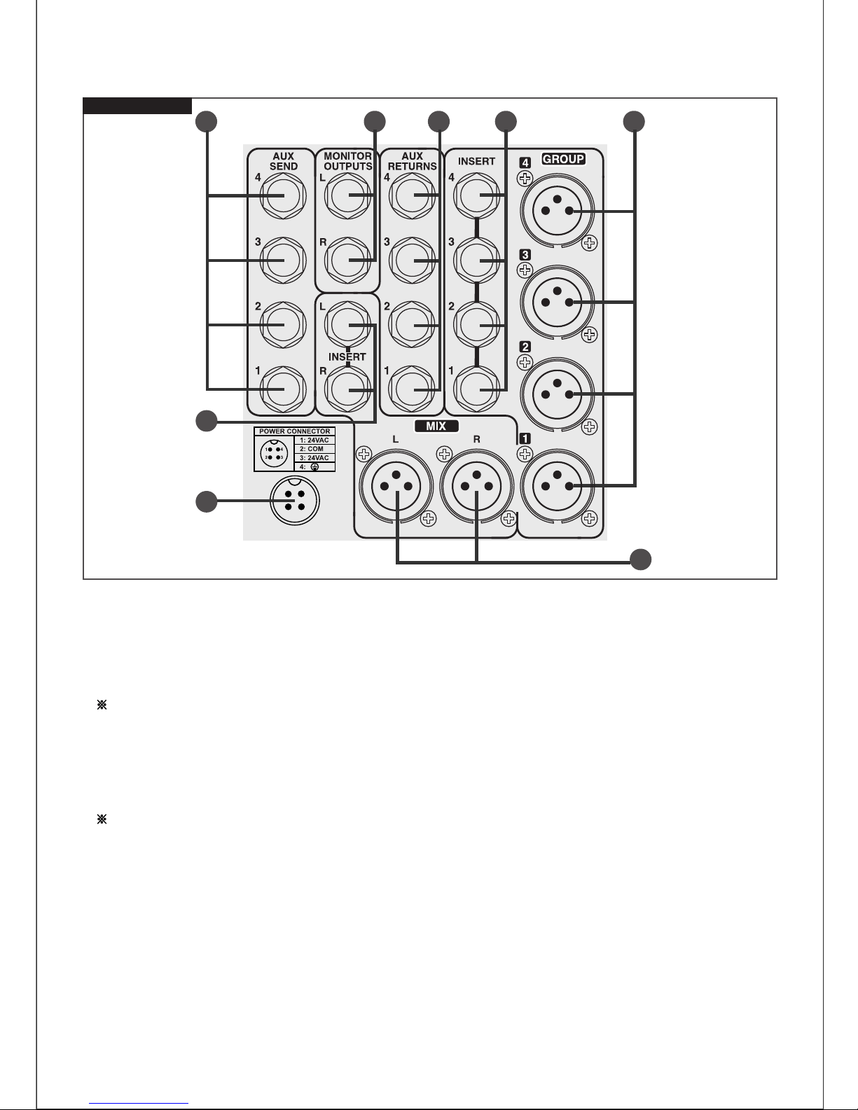
45.GROUP OUTPUTS(1~4)
46.GROUP INSERT(1~4)
These are patch points. The connectors are 1/4" phone jacks, wired balanced with the input or return signal on
the tip, the output or send signal on the ring, and the sleeve common or ground.
These patch points allow you to insert a serial processing device(such as a compressor or an equalizer)into any
of GRP insert circuits and you can modify the signals by use. The insert point is after the summing amplifier, but
before the fader.
L/R Mix output connectors are standard 3 pin XLR jacks, wired pin 2 signal '+', pin 3 signal '-', pin 1 signal
'ground'.
Output level is balanced, +4dB(1.23V RMS), when the zero(0) standard LED is lighten in meter section.
This output is where you connect power amplifier that operafe stage L/R spk. for main output in live concert.
L/R Mix inserts are 1/4" balanced phone jacks, wired with the input or return singal on the tip, the output or send
signal on the ring, and the sleeve common or ground.
There patch points allow you to insert a serial processing device(such as, a compressor or an equalizer) into any
of insert jacks. For your modifying the signals especially by use.
48.L/R MIX INSERTS
47.L/R MIX OUTPUTS
The group output connector is standard 3pin XLR, with pin 2 signal '+', pin 3 signal '-', pin1 signal 'ground'.
The output level is balanced +4dB(1.23V RMS), when the zero(0) standard LED is lighten in meter section.
STAGE PRO PANNELS
12
49.STEREO AUX RETURNS INPUTS(1~4)
The AUX returns are stereo 1/4" balanced phone jacks with left signal on the tip, right signal on the ring and the
sleeve on ground. Nominal input level is +4dB(1.23V RMS).
If you have only one signal, plugging signal'+', into the tip or the ring but the other tip or ring has to be open.
When you depress the mono switch(25) in the AUX return section on the above the GRP strip of the front panel,
the signal sent into both L and R circuits in your stereo image.
NOTE : when the product send mono output signals into the jack, if the mono switch is depressed the signal
evel is down or not operating in unplugged tip or ring's ground.
50.MONITOR OUTPUTS(LEFT, RIGHT)
The monitor output jacks are 1/4" unbalanced, wired tip'+', sleeve ground.
This is where you connect your control room monitor amplifier inputs, the nominal output level is 0dB(0.775V
RMS).
NOTE : when you use talkback mic. To prevent feedback situation, turn down the talkback level properly in the
control room.
51.AUX SENDS(1~4)
The Aux sends are 1/4" unbalanced phone jacks, wired tip to '+' and sleeve to 'ground'. These are independent
from main output section. Therefore, you can use handy them Aux outputs for. Fold back(effect or monitor output
for musician performance)or using expended speaker system.
52.POWER (Only for the Stage pro )
When the power switch is turned on, the power is supplied.
53.POWER INLET
The power inlet is the socket to supply the AC power. You turn on the power switch after plugging the AC cord.
The fuse is built in the socket.
12
3
12
3
12
3
12
3
12
3
455051
47
48
53
49 46
12
3
TRIPAC PANNELS

APPLICATIONS
13
PUBLIC ADDRESS
CHANNEL 1
0dB
5
1
2
3
4
9
8
7
6
CHANNEL 2
0dB
5
1
2
3
4
9
8
7
6
CLIP SIG PWR PWR SIG CLIP
+
-
POWER
PRO TECTION
ON
OFF
BRIDGEABLE STEREO MAIN AMPLIFIER JMA 300N
2 SPEEDS FAN
FULL PROTECTION
NEGATIVEFEEDBACK SYSTEM
ACTIVE CLIPS
CHANNEL 1
0dB
5
1
2
3
4
9
8
7
6
CHANNEL 2
0dB
5
1
2
3
4
9
8
7
6
CLIP SIG PWR PWR SIG CLIP
+
-
POWER
PROTECTION
ON
OFF
BRIDGEABLE STEREO MAIN AMPLIFIER JMA 30 0N
2 SPEEDS FAN
FULL PROTECTION
NEGATIVEFEEDBACK SYSTEM
ACTIVE CLIPS
NOISE GATE,
COMPRESSOR,
NOTCH FILTER
FROM LINE LEVEL
VOCAL MIC
JMA and AP SERIES
MAIN SPEAKER
SEND
SEND
RTN
RTN
STEREO
COMPRESSOR
JMA and AP SERIES
MONITOR
SPEAKER
TO POWER AMP
(OPTIONAL)
TO EFFECTS
(OPTIONAL)
TO POWER AMP
(OPTIONAL)
RTN
INSERT
8
CHANNEL
INSERT
7
CHANNEL
INSERT
6
CHANNEL
INSERT
5
CHANNEL
INSERT
4
CHANNEL
INSERT
3
CHANNEL
2
CHANNEL 1
CHANNEL
TIP
LINE
INPUT
AUX SEND
MON,DIRECT
STEREO
INPUT AUX
RETURN
INSERT
PHONES
RING
SLEEVE
+SIGNAL
ÐSIGNAL
GND GND GND GND GND GND
OUTPUT
N.C
ÐSIGNAL
RIGHT
LEFT
LEFT
SIGNAL
RIGHT
SIGNAL
+SIGNALINPUT OUTPUT
1
2
3
INPUT
GROUP MIX
OUTPUT
-DSIGNAL (COLD)
+SIGNAL (HOT)
SCREEN (GND)
T
R
S
S R T
2 1
3
FEMALE
XLR
1 2
3
MALE
XLR
XLRJACK
MIX
INSERT
RL
SEND MONITOR
OUTPUTS AUX
RETURNS INSERT GROUP
1
2
3
4
4
3
2
4
3
2
1
L
R
L
R
4
3
2
1
AUX
LINE
MIC
LINE LINE LINE LINE LINE
MIC MICMIC MIC MIC MIC
LINE
MIC MIC
CH A NN E L 1
0dB
5
1
2
3
4
9
8
7
6
CH A NN E L 2
0dB
5
1
2
3
4
9
8
7
6
CL IP S IG PWR PWR SIG CLIP
+
-
POWER
PRO T E C T IO N
ON
OFF
CHANNEL 1
0dB
5
1
2
3
4
9
8
7
6
CHANNEL 2
0dB
5
1
2
3
4
9
8
7
6
CLIP SIG PWR PWR SIG CLIP
+
-
POWER
PROTECTION
ON
OFF
BRIDGEABLE STEREO MAIN AMPLIFIER JMA 30 0N
2 SPEEDS FAN
FULL PROTECTION
NEGATIVEFEEDBACK SYSTEM
ACTIVE CLIPS
SEND
SEND
RTN
RTN
STEREO
COMPRESSOR
JMA and AP SERIES
MONITOR
SPEAKER
TO POWER AMP
(OPTIONAL)
TO EFFECTS
(OPTIONAL)
AMP
(OPTIONAL)
INS E R T INS E R T INS E R T INS E R T INS E R T INS E R T
C HANNE L
T IP
IN P UT
AU X S E ND
MO N, DIR E C T
S T E R E O
IN P UT
AU X
R E T U R N
INS E R T
P HO NE S
R ING
S L E E V E
+S I G NAL
ÐS IG NAL
G ND G N D G ND G ND G ND G ND
O UT P U T
N.C
ÐS IG NAL
R I G HT
L E F T
L E F T
S I G NAL
R I G HT
S I G NAL
+S I G NA LIN P U T O UT P U T
1
2
3
T
R
S
S R T
1 2
3
MALE
XLR
XL R
INS E R T
RL
SEND MO N IT O R
O UT P U T S
AU X
R E T U R N S I NS E R T G R O UP
1
2
3
4
4
3
2
4
3
2
1
L
R
L
R
4
3
2
1
AUX
MIC
LIN E L IN E L IN E L INE L INE
MIC MIC MIC MIC MIC
LIN E
MIC MIC
SEND
INSERTINSERT
LINE

14
POWER0dB
3
6
9
+12
3
6
9
-12
0dB
3
6
9
GRAPHICEQUALIZER
3
6
9
-12
Hz
JEQ-215
+12
25 40 63 100 160 250 400 630 1K 1K6 2K5 4K 6K3 10K 16K 25 40 63 100 160 250 400 630 1K 1K6 2K5 4K 6K3 10K 16K CH1 CH2
CLIP
EQ
40Hz
16KHz
CHANNEL2CHANNEL1 LEVEL
CHANNEL 1
0dB
5
1
2
3
4
9
8
7
6
CHANNEL 2
0dB
5
1
2
3
4
9
8
7
6
CLIP SIG PWR PWR SIG CLIP
+
-
POWER
PROTECTION
ON
OFF
BRIDGEABLE STEREO MAIN AMPLIFIER JMA 30 0N
2 SPEEDS FAN
FULL PROTECTION
NEGATIVEFEEDBACK SYSTEM
ACTIVE CLIPS
CHANNEL 1
0dB
5
1
2
3
4
9
8
7
6
CHANNEL 2
0dB
5
1
2
3
4
9
8
7
6
CLIP SIG PWR PWR SIG CLIP
+
-
POWER
PROTECTION
ON
OFF
BRIDGEABLE STEREO MAIN AMPLIFIER JMA 30 0N
2SPEEDS F AN
FULLPROTECTION
NEGATIVE FEEDBACK SYSTEM
ACTIVECLIPS
CHANNEL 1
0dB
5
1
2
3
4
9
8
7
6
CHANNEL 2
0dB
5
1
2
3
4
9
8
7
6
CLIP SIG PWR PWR SIG CLIP
+
-
POWER
PROTECTION
ON
OFF
BRIDGEABLE STEREO MAIN AMPLIFIER JMA 30 0N
2SPEEDS F AN
FULLPROTECTION
NEGATIVE FEEDBACK SYSTEM
ACTIVECLIPS
SEND SEND
RTN
RTN
JEQ-215
STEREO
COMPRESSOR
LIMITE
JMA and AP SERIES
STAGE MONITOR
REVERB 2
MAIN
SPEAKER
JMA and AP SERIES
DAT or 2-TRACK DECK
GUITAR
EFFECTS
BOX
SEND
RTN
RTN
SEND
NOISE GATE
MONO COMPRESSOR
VOCAL MIC DURM KITS
KEYBOARD
9/10
Channel
11/12
Channel
13/14
Channel
15/16
Channel
LR
1
2
3
4
1
2
3
4
R
L
R
L
1
2
3
4
R
L
R
L
R
L
R
L
R
L
R
L
R
L
R
L
GROUP 4
INSERT AUX
RETURNS MONITOR
OUTPUTS AUX
SEND
INSERT
DIRECT
LINE
8
Channel
MIC
INSERT
DIRECT
LINE
3
Channel
MIC
INSERT
DIRECT
LINE
2
Channel
MIC
INSERT
DIRECT
LINE
PHANTOM
POWER
CH 1-4
1
Channel
MIC
INSERT
TIP
LINE
INPUT
AUX SEND
MON,DIRECT
STEREO
INPUT AUX
RETURN
INSERT
PHONES
RING
SLEEVE
+SIGNAL
ÐSIGNAL
GND GND GND GND GND GND
OUTPUT
N.C
ÐSIGNAL
RIGHT
LEFT
LEFT
SIGNAL
RIGHT
SIGNAL
+SIGNALINPUT OUTPUT
JACK
T
R
S
S R T
12 3
MALE
XLR
1 2
3
FEMALE
XLR
1
2
3
MIX
LR
1
2
3
INPUT
GROUP MIX
OUTPUT
ÐSIGNAL (COLD)
+SIGNAL (HOT)
SCREEN (GND)
XLR
12
3
12
3
12
3
12
3
STEREO LIVE

15
TITRACK RECORDING
SEND
RTN
RTN SEND
STEREO REVERB
STEREO COMPRESSOR LIMITE
2 TRACK RECORDER
MULTI TRACK RECORDER
LR
1
2
3
4
1
2
3
4
R
L
R
L
1
2
3
4
GROUP 4
INSERT AUX
RETURNS MONITOR
OUTPUTS AUX
SEND
INSERT
DIRECT
LINE
8
Channel
MIC
INSERT
DIRECT
LINE
7
Channel
MIC
INSERT
DIRECT
LINE
6
Channel
MIC
INSERT
DIRECT
LINE
PHANTOM
POWER
CH 5-8
5
Channel
MIC
INSERT
DIRECT
LINE
4
Channel
MIC
INSERT
DIRECT
LINE
3
Channel
MIC
INSERT
DIRECT
LINE
2
Channel
MIC
INSERT
DIRECT
LINE
PHANTOM
POWER
CH 1-4
1
Channel
MIC
INSERT
1
2
3
MIX
LR
12
3
12
3
12
3
12
3
12
3
12
3
12
3
12
3

DIMENSIONS
16
31
ÁÚ
32
29
ÁÚ
30
27
ÁÚ
28
25
ÁÚ
26
242322212019181716151413121110987654321
MONITOR
MIXER
GROUP
4
STEREO 4
MONO
24
3
2
1
3
2
1
23
22
21
20
19
18
17
16
15
14
13
12
11
10
9
8
7
6
5
4
3
2
1
24 Inputs (16 Inputs, 12 Inputs, 8 Inputs)
Length
12 channel 610mm
Height & Depth
(H) 130mm
(D) 680mm
441mm(W) x 155mm(D) x 623mm(H)
483mm(W) x 182mm(D) x 489mm(H)
441mm(W) x 155mm(D) x 661mm(H)
20 channel 810mm
1
1
2
3
2 3

BLOCK DIAGRAM
18
HIGH
FREQ
MID LOW
1-2
3-4
L-R
L.R
1-4
32W/0.2W
<
=
A/PFL
RUDE
A/PFL
L
R
MIX
PAD(40dB)
+48
GAIN (40dB)
PHASE
INVERT
HIGH-PASS
FILTER
100Hz
12dB/OCT
3-BAND EQ
INSERT
POINT
ACTIVE
DETECT
EQ
IN ON FADER PAN
PRE/POST AUX-1
AUX-2
AUX-3
AUX-4
PFL
CON
CLIP
PFL
SGN
MIC/LINE
-60dB~+20dB
MIC/LINE
MONO INPUT
12
34
LR
12
34PFL
CON
GROUP BUS
AUX SEND BUS
MIX
3-BAND EQ
3-BAND EQ
MONO
HIGH MID LOW
ACTIVE
DETECT
CLIP
PFL
SGN
BAL
EQ
IN ON FADER
PRE/POST AUX-1
AUX-2
AUX-3
AUX-4
PFL
CON
1-2
3-4
L-R
STEREO INPUT
GAIN AUX 1-4
GROUP 1-4
L.R MIX
SUPPLY
POWER
+17V
GND
-17V
+48V
+24V
L
-20dB~+20dB
R
T.B
MIC
AC POWER
120/220/230V
50/60Hz
(OPTION)
INSERT
POINT GROUP
FADER
GROUP
PAN
VU MON
1-4 1-4
AFL
POWER
MUTE
VU MON
L R
POWER
MUTE
AUX
VU
1-4
PFL
POWER
MUTE
3-4 MONO
1-2
L-R
PFL
CON
1~4
L
R
1~4
GROUP OUTPUT
MIX OUTPUT
AUX SEND
AUX RETURN
L
R
MONITOR
OUTPUT
PHONES
MONO3-4
1-2
L-R
1-2
3-4
L-R
MON SELE
PFL
PFL CON
DETECT
PAD OR
1 2 3 4 L R
METER DISPLAY
MON. IN
1
1
AUX SEND
2
3
4
2
3
4
GROUP
METER DISPLAY AMP
POWER
MUTE
POWER
MUTE
L R
CON
INSERT
POINT L.R MIX
FADER
AFL
AFL
CON
INSERT
POINT
CON
BAL
AUX
A/PFL
POWER
DIRECT
PHANTOM
POWER
MONIT
PHONES
GAIN
This manual suits for next models
2
Table of contents


