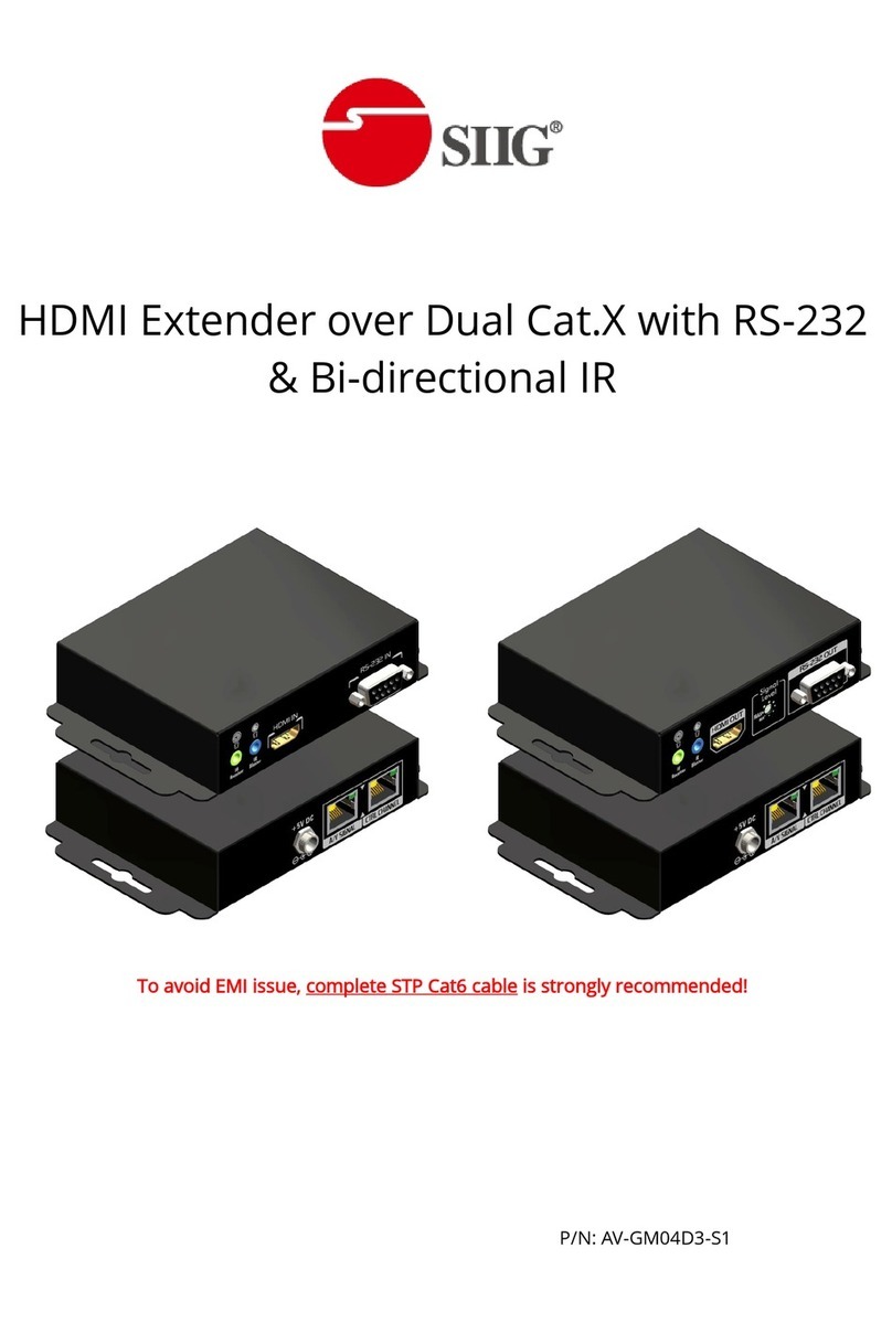
Jedia JSC-132A User manual

WWW.JEDIA.COM
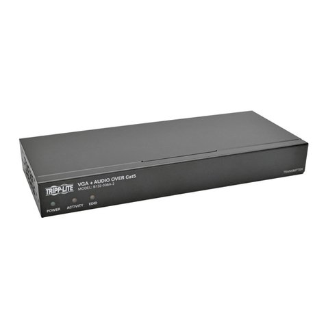
JSC-132A
SPEAKER LINE CHECKER
JSC-132D
LINE CHECK EXTENDER

LINE CHECKER EXTENDER JSC-132D
J S C - 1 3 2 A
L i n e C h e c k e r
A
(스피커 라인체크 확장 장비 전,후면)
JSC-132D

SAFETY INSTRUCTIONS
Read all safety instruction before operating the JSC-132A.
1. Install equipment as follow conditions.
The apparatus shall not be exposed to dripping or splashing and
no object filled with liquids, Such as vases, Shall be place on the
apparatus.
Install at the place, Not bending curved.
Do not install this apparatus in a confined space such as a book
case or similar unit.
Locate power amplifier away from heat source, Such as radiators
or other device that produce heat.
Do not drop objects or spill liquids into the inside of the apparatus.
2. Keep in mind the following when connecting the apparatus.
Connect the apparatus after reading of O/P manuals.
Connect each connection of the apparatus perfectly, If not, It maybe
caused hum, damage, electric shock in case of mis-connecting.
To prevent electric shock, do not open top cover.
Connect the power cord with safety after check of AC power.
This apparatus should be serviced by qualified service person.
안 전 사 항
제품을 운용하기전에 모든 안전사항을 읽어 보십시오.
1. 이런 장소에 설치하여 주십시오.
진동이나 경사가 심하지 않고 바닥이 평평한 장소.
통풍이 잘되고 물기나 습기가 많지 않은 장소.
직사광선을 받지 않는 장소 또는 난방기구(발열체)에서 멀리 떨어진 장소.
인화성 물질(화학약품)이 없는 장소.
2. 설치시 이런점을 주의하십시오.
사용설명서 시스템 연결방법을 완전히 읽으신 후에 연결해 주십시오.
각종 연결선을 완전하게 연결해 주십시오.
(주전원 코드를 뽑은 상태에서 연결.)
불완전한 연결은 잡음, 제품의 손상 또는 안전사고의 원인이 됩니다.
전기적 충격 또는 감전사고의 위험이 있으므로 뚜껑을 열지 말아주십시오.
주 교류 전원 플러그를 연결하기 전에 사용전압을 확인하신 후 안전하게
연결하십시오.
제품을 수리시는 규정된 부품과 자격이 있는 사람이 수리를 하여야 함.
1
FEATURES
특 징
Ground Fault Detection.
Speaker Line Impedance Check.
Speaker Line Open Check.
Speaker Line Over Load Check.
Speaker Line Under Load Check.
Speaker Line Short Check.
Max. 32 Speaker Lines (with 4 Relay Board).
Automatical check in adjustables time intervals between 1
minutes and 24 hours.
Double-spaced background-lighted liquid crystal display
with clear text output.
Interruption of the check when emergency announcement
comes up.
Bridging of the existing volume control with the intergrated
relay during the check.
Permissible speaker line check 100V/70V.
Store by Non volatile memory(EE-PROM)
Alert sound and LED indicator when speaker line fault.
Buzzer off function.
AC and DC 24V operation.
Standard in height desktop or 19" rack mount.
스피커 라인 그라운드 폴트 검출.
기기의 설치
스피커 라인 임피던스 체크.
스피커 라인 오픈 체크.
스피커 라인 오버 로드 체크.
스피커 라인 언더 로드 체크.
스피커 라인 쇼트 체크.
최대 32 채널의 스피커 라인 체크 : 4개의 릴레이 보드 사용시.
자동 체크를 위한 시간 간격 설정 : 최소 1 분, 최대 24 시간.
16 문자* 2 열 표시 LCD 채용.
비상상황 발생시 외부 입력에 의한 체크 정지 기능.
체크하는 동안 작동하는 2-pole 릴레이 접점.
100V / 70V 스피커 라인 체크 가능.
비휘발성 메모리 (EE-PROM) 를 사용하여 저장된 데이터 유지.
스피커 라인 폴트(fault) 검출시 경고음 발생 및 LED 점멸기능.
부저 일시 정지 기능.
AC 및 DC 24V 겸용.
표준 19" 랙 1U 사이즈.
By the set-down relay-boards, the speaker lines which have
to be checked and ranked over the existing PA system in a
very simple way. The JSC-132A central processing units is
built in the 19" rack and connected with the relay boards by
usingthe supplied interfaced cable. A complicated installation
in the existing PA-System is not necessary.
After that the JSC-132A is ready for use.
INSTALLATION
릴렐이 보드를 설치하면 스피커라인이 체크되며 아주 간편한 방법으로 P.A
시스템에 연결된다.
JSC-132A는 19" 랙에 장착 사용 가능하며 공급된 케이블을 이용하여
릴레이 보드와 연결할 수 있다.

FRONT PANEL CONTROLS (전면기능)
2
Pushing Check button, status of channel selectd is checking and
selected channel will be displayed on the LCD.
2. CHECK BUTTON
Setting of measurement interval which you want to have by this key
if time setting is over, the connected speaker lines are checked
automatically. Interval time adjustment is from 1 minutes from 24 hours.
Factory production is set up 1 hours.
3. TIME INTERVAL SETTING BUTTON
4. LCD (LIQUID CRYSTAL DISPLAY)
1). HOUR
Time setting is from 00 to 23 hours(total 24 hours) pushing the
key, time per hour is up to 23 hours and begin 00 hour after 23
hours. Pushing the button more than one second, time scanning
will be high speed up to the upper position automatically.
2). MINUTE
Minute setting is from 00 to 59 minutes. Pushing the button, it
increase one minute to the 59 minutes after that begin 00 minute
of next hour again. Pushing the more than one second, minute
scanning will be high speed up to the upper position automatically.
It displayes all information of equipment as 16 characters with two lines.
5. MEMORY BUTTON
Each checked channel and adjusted channel can be memoried by
memory button but, it should be memoried together with relative
functions as follows. Push channel selector button while pushing the
memory button to store selected channel. Adjust hour or minutes while
pushing the memory button to store adjusted hour or minutes. Push the
check button while pushing the memory button to check all channels.
7. BUZZER OFF BUTTON
6. SPEAKER LINE FAULT INDICATOR
LED indicator will be turn on under.
Fault situation which is checked speaker line as follows.
LINE OPEN : differ more than +25% from the measurement.
LINE IMP: OVER : +15% - +25% from the measurement.
LINE IMP: UNDER : -15% - -25% from the measurement.
LINE SHORT : differ less than -25% from the measurement.
LINE GROUND FAULT .
Buzzer will makes sound. Checked speaker line is in FAULT even
though one channel pushing the buzzer off button, buzzer sound will
stop. The fault alarm can only be abolished by pressing the "BUZZER
OFF" button.
8. POWER SWITCH
Power switch for AC INPUT.
Channel selector button is to check the channel you want. Range of
selection is up to 32 channels and channel step is from one to thirty
two by ranked over range and begin one channel to thirty two channels
again. If JSC-132A has memoried channel, it will be desplayed on
the LCD. Pushing the button more than one second, channel
scaning will be high speed when power on, checking operaton will
not act on under non selected button.
1. CHANNEL SELECTOR BUTTON 1. 채널 선택 버튼
이 버튼은 체크하고자 하는 채널을 선택하는데 사용됩니다. 채널의 선택범
위는 132 채널까지이며, 채널 1부터 채널 32 까지 한번에 한 채널씩 상향
조정된 후 다시 채널 1부터 시작됩니다. 이전에 체크하여 기억되었던 상태가
있으면 해당 채널의 상태가 LCD에 디스플레이됩니다. 약 1초 이상 계속
누르면 고속으로 조정됩니다. 최초로 전원이 투입되었을 경우, 이 버튼이
눌러지지 않은 상태에서는 "체크" 버튼을 눌러도 체크 동작을 하지 않습니다.
2. 체크 버튼
이 버튼을 누르면 "채널 선택" 버튼에 의해 선택된 채널의 라인 상태를 체크
하며 그 결과를 LCD상에 나타냅니다.
3. 시간 간격 설정 버튼
이 버튼들은 시간 간격을 조정하여 기억시키면 정해진 시간마다 자동으로
스피커 라인 상태를 체크합니다.
시간 간격 조정은 1분부터 24시간까지입니다.
공장출하시 기본 시간은 1 시간으로 설정되어 있습니다.
4. LCD 표시창
1). 시간
00 시간부터 23 시간까지 총 24 시간의 구간을 설정합니다.
한번 누를 때마다 한 시간씩 상향 조정되며 23시간 이후는 다시 00시간
부터 시작됩니다. 약 1초 이상 계속 누르면 고속으로 상향 조정됩니다.
2). 분
00 분부터 59 분까지 총 59 분의 구간을 설정합니다.
한번 누를 때마다 1분씩 상향 조정되며 59 분 이후는 다음 시간의 00
분부터 시작됩니다. 약 1초 이상 계속 누르면 고속으로 상향 조정됩니다.
16 문자 2 열로 구성된 LCD로서 기기의 모든 상태를 표시하는 장치입니다.
5. 기억버튼
체크된 각 채널의 상태 및 조정된 시간 간격을 기억시키거나, 모든 채널 체크
기능을 수행하는 버튼이며, 단독으로는 사용되지 않고 해당 기능을 수행하는
버튼과 함께 사용됩니다. "기억" 버튼을 먼저 누른 상태에서 "채널 선택" 버튼
을 같이누르면 체크된 해당 채널의 상태가 기억됩니다.
"기억" 버튼을 먼저 누른 상태에서 "시간" 혹은 "분" 버튼을 같이 누르면 조정된
시간간격이 기억됩니다."기억" 버튼을 먼저 누른 상태에서 "체크" 버튼을 같이
누르면 모든 채널을 체크합니다.
7. 부저음 정지 버튼
6. 스피커 라인 폴트 표시기
체크된 스피커 라인의 어느 한 채널이라도 폴트(FAULT) 상태가 있으면 이
LED가 점멸합니다.
폴트 상태란 다음의 경우입니다.
라인 오픈 : (LINE OPEN : 측정치의 +25% 이상)
라인 임피던스 오버 : (LINE IMP.-OVER : 측정치의 +15% +25%)
라인 임피던스 언더 : (LINE IMP.-UNDER : 측정치의 -15% -25%)
라인 쇼트 (LINE SHORT : 측정치의 -25% 이하)
라인 그라운드 폴트 : (LINE GROUND FAULT)
체크된 스피커 라인의 어느 한 채널이라도 폴트(FAULT) 상태가 있으면
부저가 울립니다. 이때, 이 버튼을 누르면 부저음은 정지됩니다.
8. 전원 스위치
AC 전원 입력 스위치입니다.
JSC-132A
SPEAKER LINE CHECKER
MEMORY FAULT BUZZER OFF POWER
CHANNEL
SELECTOR CHECK HOUR MINUTE
INTERVAL
1 2 5 7 86
3 4
J S C - 1 3 2 A
L i n e C h e c k e r

3
1. AC INLET SOCKET
This is AC power cord socket. Please connect the power
cord after main power switch "off".
2. AC FUSE HOLDER
This is AC fuse holder.
IMPORTANT NOTICE: When fuse is blown out, it should
be replaced with the same type fuse like following table, if
it continuous to blown out, stop replacing fuse and refer
servicing to qualified person.
120V AC F500mAL 250V (N51)
F200mAL 250V (50F)220/230/240V AC
1. 교류 전원 공급용 소켓
교류전원 공급용 소켓이며, 전면의 주전원 스위치가 "OFF"된 상태
에서 전원코드를 끼워 주십시오.
교류전원용 휴즈 홀더입니다.
2. 교류 전원 휴즈용 홀더
중요사항 : 휴즈를 교체시에는 반드시 규정된 정격 휴즈를 자격
이 있는 사람이 교체하십시오.
REAR PANEL CONTROLS (후면기능)
AC 230V /50Hz
FUSE RATING
F200mAL 250V
Measuring
disabled Fault RELAY BOARD-3 RELAY BOARD-2 RELAY BOARD-1
Channel
32 25 24 17 16 9 81
Channel Channel Channel
Make contact
during measurement
23W
RELAY BOARD- 4
on
off
on
off
on
off
on
off
WARNING:
TO REDUCE THE RISK OF FIRE
OR ELECTRIC SHOCK
DON'T EXPOSE THIS
EQUIPMENT TO RAIN OR MOISTURE.
CAUTION:TO REDUCE
THE RISK OF FIRE REPLACE
ONLY WITH SAME TYPE FUSE.
MADE IN KOREA
MODEL NO.: JSC-132A
CAUTION
RISK OF ELECTRIC SHOCK
DO NOT OPEN
SERIAL NO.:
DC POWER
24V/0.5A
1 72
3 4 5 6 8
3. DC 24V INPUT TERMINAL
This is terminals for DC 24V battery power supply, when
unexpected AC power failure.
Fuse is Built in PCB F1.
Fuse Rating(휴즈정격)
3. 직류 24V 전원 입력 단자
교류 전원이 정전되었을 때 배터리로부터 DC 24V 전원을 공급받는
직류 전원 입력단자 입니다.
휴즈는 제품 내부의 PCB상의 F1입니다.
4. MEASURING DISABLED DRY CONTACT INPUT TERMINAL
Connection possibility of an potential-free contact for suppressing
the measurement.
5. FAULT RELAY CONTACT
1 normally-open relay contact when "fault" is measured.
(only when JSC-132A is active)
6. MAKE CONTACT DURING MEASUREMENT
2 normally-open relay contact activated during a measurement.
(for example for bridging the volume-control)
7. RELAY BOARD CONNECTORS
4 pcs of Relay boards are acceptable to connect as a connector
which is connecting 8 channel relay board.
8. CHANNEL ON/OFF SWITCHES
This is channel ON/OFF switch which is setting of check or not
at relative channel relay board connected.
"ON" position makes checking at each channel, "OFF" position
makes no checking
4. 측정 정지 입력 단자
이 두 단자를 접촉시키면 접촉이 해제될 때까지 모든 체크 동작이
정지 됩니다.
5. 폴트 릴레이 접점
체크된 스피커 라인의 어느 한 채널이라도 폴트(FAULT) 상태가
있으면 동작 되는 릴레이 접점입니다.
6. 측정시 메이크 접점
체크시에만 동작되는 릴레이 접점으로 작동시간은 약100m sec
입니다.
7. 릴레이 보드 연결용 콘넥터
각 8 채널의 릴레이 보드를 연결하는 콘넥터로서 총 4 개의 릴레이
보드를 연결할 수 있습니다.
8. 채널 설정 ON/OFF 스위치
연결된 릴레이 보드의 해당 채널의 체크 여부를 설정하는 스위치입
니다.
각각의 채널을 "ON" 위치로 설정하면 체크하고, "OFF" 위치로 설정
하면 체크하지 않습니다.
DC 24V T1AH 250V (55T)

4
1. AMP INPUT TERMINALS
Input terminal for amplifier signal of each channel.
1. 앰프 신호 입력 단자
각 채널의 앰프 신호를 입력하는 단자입니다.
2. AMP OUTPUT TERMINALS
Output terminal for amplifier signal of each channel.
Also output terminal for measured signal while measuring.
3. RELAY BOARD CONNECTORS
Connector for relay board and equipment.
Connect cable while is included in the relay board or cable
in the equipment.
2. 앰프 신호 출력 단자
각 채널의 앰프 신호를 출력하는 단자입니다.
측정시에는 측정 신호가 출력되는 단자입니다.
3. 릴레이 보드 콘넥터
JSC-132D를 기기(JSC-132A)와 연결하는 콘넥터입니다.
기기 내부에 포장되어 있는 케이블 혹은 JSC-132D에 포함되어 있는
케이블을 사용하여 연결합니다.
1
LINE CHECKER EXTENDER JSC-132D
AMP IN
1~8 CHANNEL
AMP IN
9~16 CHANNEL
MODEL: JSC-132D
LINE CHECKER EXTENDER
TO JSC-132A RELAY BOARD
CHANNEL 9 ~ 16
CHANNEL 25 ~ 32
CHANNEL 1 ~ 8
CHANNEL 17 ~ 24
SPEAKER OUT
1~8 CHANNEL
SPEAKER OUT
9~16 CHANNEL
JSC-132A와 연동하여 스피커라인 체크 확장 장비.
16채널의 앰프 입력과 스피커 출력이 가능.
기존의 확장팩과 달리 렉 장착이 가능하며 보관 설치가 용이함.
별도의 입력 전원이 없음.
16 Channel
16 Channel
10Bit(1024 Step)
483(W) x 44(H) x 200(D)mm
2.9kg
신호 입력
신호 출력
ADC 분해능력
규 격
중 량
(스피커 라인체크 확장 장비 전,후면)
JSC-132D
(규격 및 성능)
SPECIFICATIONS
JSC-132D의특징
2 3

5
OPERATING METHOD (동작 방법)
It displays on the LCD as follows when power on. 전원이 인가되면 LCD상에 다음과 같이 표시되어 3회 점멸합니다.
If no record of previous fault data on the unit, it decrease time
by second and displays automatic checking time selected by
user.
이전에 기록되었던 폴트 상태가 없으면 사용자가 설정한 자동 체크
시간이 표시되며 초단위로 감소합니다.
(Int.=Interval)
(H=Hour, M=Minute, S=Second)
(Ext.=External)
ex) In case of ch 3 fault.
(예 :채널 3 이 그라운드 폴트인 경우 다음과 같이
표시 됩니다.)
If record of previous fault data on the unit, it displays status of
fault and relative channel. (Buzzer will be operated in actual
fault data only)
이전에 기록되었던 폴트 상태가 있으면 해당 채널과 상태가 표시
됩니다. (실제로 체크된 경우가 아니면 부저는 동작하지 않습니다.)
J S C - 1 3 2 A
L i n e C h e c k e r
1. CHECKING PER CHANNEL AND MEMORY 1. 채널별 체크 및 기억 방법
1) "CHANNEL SELECTOR" 버튼을 사용하여 체크하고자 하는 채널을
선택합니다.
해당 채널의 입력 값이 표시됩니다.
It displays status of each channel which was memorized. 기억되었던 각 채널의 상태가 표시됩니다.
It displays status of memorized channel after release of
"CHECK STOP" on the rear panel or after 10 seconds from the
pushing button on the front panel.
전면의 각 버튼을 누른 후 일정 시간(약 10초)이 경과하거나 후면의
"체크정지" 입력이 들어왔다가 해제된 이 후에는 다시 이전에 기억
되었던 각 채널의 상태가 표시됩니다.
It displays on the LCD as below and stop all operatings incase
of "input CHECK STOP" on the rear panel
1) Select the channel by CHANNEL SELECTOR.
It displayes standard level of memorized channel adjustment.
후면의 "체크정지"가 입력된 경우에는 다음과 같이 표시되어 점멸
하며, 해제시까지 모든 동작은 정지됩니다.
해당 채널의 릴레이 보드가 연결되지 않았다면 "Not connected!"
가 표시되며, "CHECK" 버튼을 눌러도 체크는 수행되지 않습니다.
It will be displayed "not connected" on the LCD, if relative
relay board is not connected and it will not act on check even
though pushing the "CHECK" button.
해당 채널의 릴레이 보드가 연결되어 있더라도 해당 채널의
스위치가 "OFF"된 상태이면 "Switch Off!"가 표시되며, "CHECK"
버튼을 눌러도 체크는 수행되지 않습니다.
It will be displayed "SWITCH OFF" on the LCD, if status of
switch is OFF and it will not check even though pushing the
"CHECK" button.
E x t . I n p u t t e d !
M e a s u r e D i s a b l e d
C h 0 1 1 0 0 W A T T
C o n n e c t e dN o t
S w i t c h O f f
!
I n t . R e s t T i m e
H : M : S = 0 1 : 0 0 : 0 0
C h 3
G r o u n d F a u l t !
①
②
③
②
③
①
C h 0 1 1 0 0 W A T T
C h 0 1 1 0 0 W A T T

6
OPERATING METHOD (동작 방법)
2) "CHECK" 버튼을 놀러 체크합니다.
체크가 시작되면 "Checking!" 이라는 메세지가 표시됩니다.
2) Pushing the CHECK button to check.
3) "MEMORY" 버튼을 먼저 누르고 있는 상태에서 "CHANNEL" 버튼
을 같이 누르면 현재의 수치가 새로운 기준치로 기억되며 기억되는
동안 메모리를 시험하여 그 상태를 표시합니다.
메모리에 이상이 없고 새로운 기준치가 올바르게 기억되면
"Writing Ok!"를 표시하고, 메모리에 이상이 있거나 새로운 기준
치가 올바르게 기억되지 않으면 "Back-Up Error!"를 표시합니다.
("Back-Up Error!"가 표시된 경우에는 기기 내부의 해당 메모리를
동일한 제품으로 교환하여 사용하여야 합니다.)
3) New standard value will be memoried from current memory,
when pushing the CHANNEL button while memory button
is pushed first and display status of memory as follows
"Writing ok" when new standard value is memoried and
good memory chip without error "Back-up error " when new
standard value is memoried and bad memory with error
(if it displayes "Back-up error"on the LCD, change fault
memory into new one with same type)
4) 한번 더 "CHECK"를 눌러 최종 상태를 체크합니다.
4) One more press the "CHECK" button and finished the process.
C h e c k i n g !
Then, it displayes "CHECKING" on the LCD.
When finishing the CHECK, it displayes detailed value on
the LCD and compare previous memory value .
As a result of compared value between previous one and
new one, if there is discrepancy, it will be displayed status
on the LCD as below.
Differ more than +25% from the measurement : "Line open"
+15% - +25% from the measurement : "Line Imp.-over"
-15% - +15% from the measurement : "Line Good"
-15% - -25% from the measurement : "Line Imp.-under"
less than -25% from the measurement : "Line short"
incase of grand fault, "Ground Fault". Buzzer makes sound
and LED is turn on in case of no" Line Good".
ex). For the previous standard value is 100 and channel
is NO 1, the below is figure.
이 후 체크가 완료되면 체크된 수치가 표시되고, 이전에 기억되
었던 기준치와 비교된 후 그 상태가 표시됩니다.
표시되는 상태는 이전에 기억되었던 기준치와 비교하여 기준치의
+25% 이상은 "Line Open!", 기준치의 +15% +25% 까지는
"Line Imp.-over!", 기준치의 -15% +15% 까지는 "Line Good!",
기준치의 -15% -25% 까지는 "Line Imp.-under!", 기준치의
-25% 이하는 "Line Short!", 그라운드 폴트인 경우에는 "Ground
Fault!"가 표시됩니다.
또한 Line Good 상태가 아닌 경우에는 폴트상태를 나타내기
위하여 부저음이 울리며 이와 동시에 LED가 점멸됩니다.
예)채널이 1번이고 이전에 기억되었던 기준치가 100 이였을 경우의
상태표시.
C h 0 1 1 2 5
L i n e O p e n !
C h 0 1 W A T T7 5
L i n e S h o r t ! G r o u n d F a u l t !
C h 0 1
C h 0 1 8 0 W A T T
W r i t i n g O k !
C h 0 1 8 0 W A T T
B a c k - U p E r r o r !
C h 0 1 1 0 0 W A T T
W A T T
C h 0 1 1 0 0 W A T T
L i n e G o o d !
L i n e I m p . - o v e r !
C h 0 1 1 1 5 W A T T
L i n e I m p . - u n d e r !
C h 0 1 8 5 W A T T

7
OPERATING METHOD (동작 방법)
1) 최초로 "HOUR" 혹은 "MINUTE" 버튼을 누르면 기본 설정 시간이
표시됩니다.
1) It displays basic time setting when you push "HOUR", MINUTE"
button initially.
2) "HOUR" 버튼을 한번 누를 때마다 시간이 상향 조정되며, 조정
시간은 00 23 시간입니다.
"HOUR" 버튼을 계속 누르면 시간이 고속으로 상향 조정됩니다.
2) Whenever pushing "Hour" button, time interval setting is adjusted
toward upper position. Time interval is from "00" to 23 hours pushing
the "HOUR "button continuously, time interval scanning will be high
speed to the upper position.
4) 시간 간격의 설정 완료 후, "MEMORY" 버튼을 먼저 누르고 있는
상태에서 "HOUR" 혹은 "MINUTE" 버튼을 같이 누르면 현재 표시
된 시간이 기억됩니다. 메모리에 이상이 없고 새로운 시간 간격이
올바르게 기억되면 "Writing Ok!"를 표시하고, 메모리에 이상이
있거나 새로운 시간 간격이 올바르게 기억되지 않으면 "Back-Up
Error!"를 표시합니다.
("Back-Up Error!"가 표시된 경우에는 기기 내부의 해당 메모리를
동일한 제품으로 교환하여 사용하여야 합니다.)
4) Current time setting will be memoried when pushing "HOUR"
button or "MINUTE" button while pushing the MEMORY button
after time setting. "Writing ok" when new time interval is memoried
and good memory chip without error "Back-up error " when new
time interval is memoried and bad memory with error .
(if it displayes "Back-up error"on the LCD, change fault memory
into new one with same type)
3) "MINUTE" 버튼을 한번 누를 때마다 분이 상향 조정되며, 조정
시간은 00 59 분입니다.
"MINUTE" 버튼을 계속 누르면 분이 고속으로 상향 조정됩니다.
(시간이 0인 경우에는 최소시간 3분으로 조정됩니다).
예)최소시가 00시간 03분인 경우 및 최대 시간 23시간 59분인 경우
의 표시.
3) Whenever pushing the "MINUTE" button, minute interval setting is
adjusted toward upper position the range of interval adjustment is
from "00 " to 59 minutes pushing the "MINUTE" button continuously,
minute interval setting will be high speed to the upper position
(minimum setting range is 3 minute even required minute is "0".
ex) display of time interval setting from "00" hour 3 minutes
minimum and 23 hour 59 minutes maximum.
2. TIME INTERVAL 2. 시간 간격 설정 및 기억 방법
본 기기는 사용자가 설정한 시간 간격마다 자동으로 모든 채널을
체크하는 편리한 기능을 채용하고 있습니다.
시간 간격은 최소 1분 최대 24시간 입니다.
It is convenient function which is checking at all channels
automatically according to user's time setting. Time setting
interval is from 1 minute still 24 hours.
3. ALL CHANNEL CHECK 3. 전체 채널 자동 체크
"MEMORY" 버튼을 먼저 누르고 있는 상태에서 "CHECK" 버튼을
같이 누르면 연결되어 있는 모든 채널을 체크합니다.
표시상태는 채널별 체크와 동일 합니다.
인터벌 시간이 길게 설정되어있고, 장시간 기기를 꺼둔 다음 다시 켠
뒤에는 전체 채널을 자동체킹 하기 바랍니다.
All channels connected will be checked, when pushing the
"CHECK" button while pushing the"MEMORY" button.
Display on the LCD is same as that of checking.
We recommand you to start auto checking of all channels in
case setting of interval time is long or long term not working.
4. BUZZER OFF
4. 부저음 정지
체크된 채널 중 어느 한 채널이라도 폴트 상태가 있는 경우 부저음이
울리게 됩니다. 이 때, 부저음을 정지하려면 이 버튼을 누릅니다.
(LED는 계속 점멸합니다.)
whenever one channel is under fault, buzzer will makes sound
with lighting. Push to stop buzzer sound.
T i m e I n t e r v a l
0 0 H : 0 0 M
T i m e I n t e r v a l
0 0 H : 0 3 M
T i m e I n t e r v a l
2 3 H : 5 9 M
C h 0 1 8 0 W A T T
W r i t i n g O k !
C h 0 1 8 0 W A T T
B a c k - U p E r r o r !

8
OPERATING METHOD (동작 방법)
1) 기기의 조정
AC 및 DC 전원을 모두 차단합니다.
전원을 인가합니다.
TP3 혹은 TP4가 AC 1.767Vrms가 되도록 VR3을 조정합니다.
TP7이 AC 3.536Vrms가 되도록 VR1를 조정합니다.
J9의 SHORT RING을 제거합니다.
TP8이 DC 0Vrms가 되도록 VR2를 조정합니다.
J9의 SHORT RING을 원위치에 연결합니다.
J15의 "CAL" 혹은 "REM" 위치에 SHORT RING을 연결하면 다음
과 같이 표시됩니다.
1) Calibration
Power AC/DC off.
5. INITIALIZATION 5. 기기의 초기화
주의 : 부적절한 초기화 실행시 기기의 성능에 오차를 발생시킬
수 있습니다.
초기화 실행시에는 AC 조정을 위하여는 오디오 아날라이저와
오실로스코프를 사용하고, DC조정을 위하여는 디지털 메타를
사용합니다.
WARNING:
It may occar difference in case of inproper initialization. So you
are strongly not recommand to initialize unit except necessity.
Use audio analyzer and oscilloscope for AC adjustment.
Power on.
Adjust VR3 of TP4 or TP7 to be AC 1.767Vrms.
Adjust VR3 of TP7 to be AC 3.536Vrms.
Remove short ring of J9.
Adjust VR2 of TP8 to be DC 0Vrms
Connect short ring of J9.
When connecting short ring to "REM" or "CAL" of J15, it
displays as below.
2) 메모리 소거
2) Memory Clear
Power AC/DC off.
Connect short ring to "MCLR" or "CLR" of J15.
Power AC/DC "on" then, it displays as follows.
When clear memory successfully, it displays as follow.
It displays as follows when removing short ring on the "CLR",
"MCLR" of J15.
If calibration is finished successfully.
It displays as below.
Remove short ring on the "J15" or "REM" after checking
repeat of 1-8, "1-9" processing.
(SW = Switch)
(Int.=interval), (H=Hour, M=minute)
C a l i b r a t i o n !
1 0 2 2
C a l i b r a t i o d !n ne
R e m o v e ' C A L ' S W !
C a l i b r a t i o d !n ne
R e m o v e ' C A L ' S W !
C a l i b r a t i o d !n ne
R e m o v e ' C A L ' S W !
I n t .
0 0 H 0 3 M
T i m e S t o r e ! I n t .
0 0 H 0 3 M
T i m e S t o r e !
I n t .
W o r k i n g O k !
T i m e S t o r e !
①
②
③
④
⑤
①
②
③
⑥
⑦
⑧
⑨
⑩
④④
⑤
①
기기의 조정이 완료되면 다음과 같이 표시됩니다.
②
③
AC 및 DC 전원을 모두 차단합니다.
J15의 "MCLR" 혹은 "CLR" 위치에 SHORT RING을 연결합니다.
전원을 인가하면 다음과 같이 표시됩니다.
메모리가 모두 소거되면 다음과 같이 표시되어 점멸합니다.
J15의 "MCLR" 혹은 "CLR" 위치의 SHORT RING을 제거하면
다음 순서로 표시됩니다.
(이후는 동작 방법에 준하여 수행됩니다.)
①
②
③
④
⑤
⑥
⑦
⑧
⑨
1-8과 1-9의 표시가 반복되는 것을 확인 후 J15의 "CAL" 혹은
"REM" 위치의 SHORT RING을 제거합니다
⑩
⑤

SPECIFICATIONS (규격 및 성능)
TECHNICAL
Check range 20~1600
Check Time Less Than 100m sec / Channel
Signal Input 32 Channel (With 2 Relay Board)
Signal Output 32 Channel (With 2 Relay Board)
ADC Resolution 10Bit (1024 Step)
Specifications and design subject is changed without notice for improvements.
(내용상의 규격 및 특징은 제품의 성능 향상을 위하여 사전 예고 없이 변경될 수 있습니다.)
GENERAL
NOTE
Dimensions
Weight 3.0kg / 6.6Ibs
483(W) x 44(H) x 200(D)mm
19(W) x 1.7(H) x 7.9(D)inch
Power Source(Option) AC 120V/220V/230V/240V 50~60Hz
DC 24V
Power Consumption 23W
JSC-132A
AMP IN
1~8 CHANNEL
AMP IN
9~16 CHANNEL
MODEL: JSC-132D
LINE CHECKER EXTENDER
TO JSC-132A RELAY BOARD
CHANNEL 9 ~ 16
CHANNEL 25 ~ 32
CHANNEL 1 ~ 8
CHANNEL 17 ~ 24
RELAY
GROUP
SPEAKER
POWER
AMP
2-wire 결선권장
SPEAKER OUT
1~8 CHANNEL
SPEAKER OUT
9~16 CHANNEL
9

JSC-132A
OPERATING INSTRUCTIONS
4M-OP206270
060705
SPEAKER LINE CHECKER
JSC-132D
LINE CHECK EXTENDER
This manual suits for next models
1
Table of contents

