Cablematic VGA CAT5 Extender User manual


Table of Content
■Introduction………………………………………………….………… 2
■Overview…………………………………………………….......... 2
■Features………………………………………………………….... 3
■Package Content..……………………………………….……….. 4
■CAT5 Cable..............…………………………………………….......... 5
■Installation…………………………………………………………....... 6
■Connection Pattern……………….…………………………..…. 7
■Complete Connection Methods………………………………... 8
■Operation……………………………………………....................… . 12
■LED Display….……..………………………………………….. .. 12
■LED Selection………………………………………………….... 14
■Output Signal Adjustment…….…………………………….. .. 18
■Video Compensation………..….…………………………….... 19
■EDID Copy…………………………………….………………..... 20
■Appendices…………………………………………………………. .. 22
■Specifications………………………………………..………... 22
Please read this manual thoroughly and follow the Installation
procedures to prevent any damage to the Unit or any connecting device
*
To prevent damages to your installation, it is important that all devices are properly
grounded.
*
The final specifications are based on the actual product.
*
Features and functions may be added or changed after the manual was written.
Please visit our website to download the latest version of manual for reference.
RoHS
1

2
-----------------
Introduction
Overview
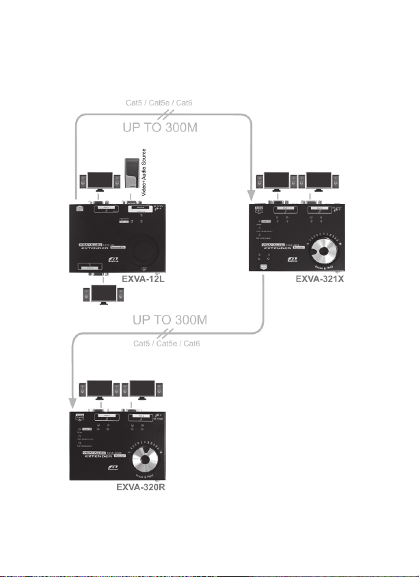
The “Video+Audio CAT5 Extender” pair consists of one Local Unit
(Transmitter) and one Receiver Unit featuring to transmit Video+Audio
signals with the resolution up to WUXGA (1920 x 1200) / Full HD (1920 x 1080)
/ UXGA (1600 X 1200) via CAT5 cables. The Local Unit duplicates the
Video+Audio signals from one input source port to one or two local output
port(s) and transmits (duplicates) the Video+Audio signals to 1/4/8 Receivers /
Repeaters (Remote Unit) via the CAT5 connector; the Remote Unit
broadcasts the signal through two local output ports. A handy jog wheel on the
top panel allows users to manually adjust audio volume and video signal on
Gain (Brightness), Equalizer (Sharpness) and RGB skew in a way that is
simple and convenient. Better yet, the signal transmission distance can be
extended for another 200/300 meters by adding one more Repeater Unit in
between the Transmitter and Receiver, and up to two Repeater Units can be
added in between to achieve the maximum transmission distance up to 900
meters.
The “Video+Audio CAT5 Extender” pair is a dedicated design with the
characteristics of Flexibility in extending video signals at high resolution over
long distances, Convenience in manually and intuitively adjusting audio and
video signal via a built-in jog wheel, Security in allowing to locate computers in
the back room or secure location away from the display and protect it from
unauthorized use or public display, and Noise Reduction in removing the noisy
computer from the broadcast studio for the perfect and uninterrupted sound
reproduction. This makes it a great solution for public broadcasting, exhibits,
retail stores, courtrooms, stock tickers, and many more applications.

Features
■Compatible with most of the popular screen resolution of WUXGA (1920 x
1200) / Full HD (1920 x 1080) / UXGA (1600 X 1200)
■Transmit the superb quality of VGA+Audio signals via CATx technology to
300 meters away or up to 900 meters with 2 repeaters in between
■Unique Equalizer (sharpness) / gain (brightness) adjustment via built-in jog
wheel for optimal video quality
■Distinctive RGB skew adjustment via built-in jog wheel for the best video
quality
■Independently turn ON/OFF the audio & video of local ports respectively (8
levels of fine tune available for audio volume adjustment)
■Automatically detecting and indicating the source video signal
■EDID Copy function makes the optimal high resolution for your application
■Support the surge protection
■Beeps confirmation for the built-in jog wheel control makes the operation
easier and cross-check
■Simple LED indication for easy status monitoring
■Ideal for public broadcasting, exhibits, retail stores, courtrooms, stock tickers,
bus stations, and so on
3

Package Content
Package For One Set Quantity
Extender Local Unit (Transmitter) 1
Extender Receiver Unit 1
Power Adapter with necessary AC Cord
OR
Plug-in Power Adapter
2
Ground Wire 2
User Manual 1
Foot Pad Set 1
Package For One Unit Quantity
Extender Unit (Repeater) 1
Power Adapter with necessary AC Cord
OR
Plug-in Power Adapter
1
Ground Wire 1
User Manual 1
Foot Pad Set 1
Optional
●Audio Cable
●VGA Cable
4

-----------------
CAT5 Cable
The Extender Pair requires a piece of UTP (Unshielded Twisted Pair) CAT5
cables.
The cable must be wired according to the EIA/TIA 568B industry standard as
shown below.
Pin Wire Color Pair
1 White/Orange 2
2 Orange 2
3 White/Green 3
4 Blue 1
5 White/Blue 1
6 Green 3
7 White/Brown 4
8 Brown 4
NOTE: CAT5, CAT5e or CAT6 cables are applicable to the extender pair.
The above diagram shows the RJ45 connector of a CAT5 cable with its metal
contacts facing up.
5

-----------------
Installation
WARNING
●Prior to the installation, ensure to power off all devices that will be
connected to this system.
●Ensure that all devices you will connect are properly grounded.
●Place cables away from fluorescent lights, air conditioners, and machines
that are likely to generate electrical noise.
●Avoid pressing or rotating the jog wheel too hard; excessive force on the
jog wheel may cause it sluggish in response or damage.
Grounding
To prevent any damage to the product or any connecting device, it is important
to make sure that the devices are properly grounded.
6

Connection Pattern
The following figures show typical applications of Extender series. The model you
have purchased may be slightly different from those described in the illustrations.
(Video+Audio)Transmitter
LocalUnit(EXVA-12L) LocalUnit(EXVA-118L)(optional)
(Video+Audio) Receiver (Video+Audio) Repeater (optional)
(EXVA-320R) (EXVA-321X)
7

Complete Connection Patterns
NOTE: Except the CAT5 cable, Video source, Audio source and power supplies,
not all devices shown below are required for the pair to operate.
Pattern 1: Transmitter Unit + Receiver Unit
Achieve the total signal transmission distance of 300 meters as the
diagram shown below.
Example of EXVA-12L and EXVA-320R
8

Pattern 2: Transmitter Unit + Repeater Unit + Receiver Unit
Achieve the total signal transmission distance of 600 meters.
9

Pattern 3: Transmitter + Repeater + Repeater + Receiver
Achieve the total signal transmission distance of 900 meters as the
diagram shown below.
Example of EXVA-12L, EXVA-321X, and EXVA-320R
10

Pattern 4: Transmitter + Repeater + Repeater + Receiver
Achieve the total signal transmission distance of 900 meters as the
diagram shown below.
Example of EXVA-118L, EXVA-321X, and EXVA-320R
11

----------------
Operation
LED Display
Local Unit (Transmitter)
12
EXVA-12L
1 Green: Power On
Flashing: EDID Copy Status
2 Blue: Video Source detected
Local Unit (Transmitter)
EXVA-114 / 118L
1 Green: Power On
Blue: Video Source detected
Flashing: EDID Copy Status
V1 Video Output Signal
A1 Volume Indication
EVx Cat5 Video Output Signal
EAx Cat5 Audio Output Signal

Receiver Unit (EXVA-220R / 320R)
/Repeater Unit (EXVA-321X)
13
Remote Unit (EXVA-321X)
V1,V2 Video Output Signal
A1,A2 Volume Indication
M1 Equalization Mode Indication
M2 Gain Mode Indication
Green: Power On
Blue: Skew Mode for Blue
M3
Green: Skew Mode for Green
Red: Skew Mode for Red
EV1 Cat5 Video Output Signal
EA1 Cat5 Audio Output Signal

LED Selection
Transmitter Unit for 4-Port and 8-Port Models
There is a jog wheel on the top panel of 4/8-port Transmitter Unit, which can be
used to turn on/off the video signal output adjust the volume. A set of LEDs on the
top panel of the Unit is divided into two groups (as the figure shown below), namely,
“Group 1” that includes the video-audio pair LEDs on each of the local output
port and remote (CAT5) output ports 1, 2, 3, 4. (for both 4-Port and
8-Port models)
“Group 2” that includes the video-audio pair LEDs on each of the remote
(CAT5) output ports 5, 6, 7, 8. (available for 8-Port model only)
LEDs of Group 1 and
Group 2 on 8-Port
Transmitter
Group Selection (for 8-Port model only)
Step 1. Power on the Unit, the LED “Power/EDID Copy” will illuminate GREEN,
and the rest of the LEDs on the Unit will illuminate ORANGE.
Step 2. Connect the source computer to the input port on the Unit, the LED
“Power/EDID Copy” will turn to BLUE indicating that the signal input
is activated and the Unit is ready for configurations.
Step 3. Press and Hold the jog wheel for about 2 seconds, the LEDs on
both groups will flash ORANGE alternatively; then, users can
release the jog wheel to select the desired group.
Port Status Selection (Video/Audio)
Each output port associates with a pair of video and audio LEDs on the top
panel of the Unit. Within about 20 seconds after one group selected, users
can press the jog wheel once to switch the status port between video/audio.
14

For instance, the video LED on the remote output port 2 flashes ORANGE
indicating that the video signal of the output port 2 is selected. Before time
out (20 seconds), users can press the jog wheel once to switch the status
port from video to audio on the port 2.
Group 1 Output Signal Selection
As the figure shown below, the first LED (Monitor) flashes indicating that the
current output video signal is selected. Users can press the jog wheel once
at a time to switch port in sequence between video/audio among the output
ports of Group 1.
Monitor
Group 2 Output Signal Selection (for 8-Port model only)
As the figure shown below, the first LED (Monitor) flashes indicating that the
current output video signal is selected. Users can press the jog wheel once
at a time to switch port in sequence between video/audio among the output
ports of Group 2.
Monitor
NOTE: The Unit will automatically resume Stand By mode, if there is no jog
wheel activity detected within 20 seconds since the last activity
15

Receiver/Repeater Unit
There is a jog wheel on the top panel of Receiver Unit and Repeater Unit
respectively, which can be used to turn on/off the video signal output, adjust
the volume or adjust the video compensation. A set of LEDs on the top panel of
the Unit are divided into two groups, namely,
“Group A” that includes the video-audio pair LEDs on local output port(s) and
remote (CAT5) output port(s). (The remote output ports are available
for Repeater Unit only)
“Group B” that includes the LEDs of Skew (GBR), Gain (Brightness), and EQ
(Sharpness).
Group Selection
Step 1. Power on the Unit, the Skew LED will illuminate GREEN indicating that
the power is on and the Unit is ready for configurations.
Step 2. Press and Hold the jog wheel, the LEDs of group A and group B will
flash alternatively, and then release the jog wheel to select the desired
group. In general, users need to access to Group A for selecting an
output port (video or audio) first.
NOTE: The Unit will automatically resume Stand By mode (Group A and B
flashing alternatively), if there is no jog wheel activity detected within
20 seconds since the last activity
16

Group A Output Signal Selection:
As the figure shown below, the first LED (Monitor) flashes indicating that the
current output video signal is selected. Users can press the jog wheel once at a
time to switch one port selection in sequence among the LEDs of group A.
Switching cycle for port selection on Receiver Unit
Switching cycle for port selection on Repeater Unit
Group B EQ/Gain/Skew Status Selection:
As the figure shown below, the first LED (EQ) flashes indicating that the
sharpness adjusting is activated, and users can press the jog wheel once at a
time to switch one status selection in sequence among the LEDs of group B.
Switching cycle for video adjustment on Receiver / Repeater Unit
NOTE: The Skew LEDs is a triple LED indicating three skew status such as
B(Blue), G(Green) and R(Red)
17

Output Signal (Video/Audio) Adjustment
Group (1,2,A) Output Signal Adjustment:
When one of the output statuses (video/audio) among these groups is
selected, the selected LED will flash indicating the activation; users can turn
the jog wheel by following the clockwise / counterclockwise direction to turn
on/off the video signal or to increase / decrease the volume as the diagram
shown below
The selected audio LED will emit ORANGE light according to the volume
strength. When users turn the jog wheel clockwise, the volume increased
and the ORANGE light strengthened, and vice versa. The diagram below
provides a comparison between the LED light strength and volume of OFF ~
7 levels.
NOTE:The CAT5 audio output signal on the Repeater Unit is not tunable
NOTE: Exit the mode through either one of the operation below.
Leave the Unit idle (no activity) for 20 seconds.
Press and Hold the jog wheel for two seconds.
18

Video Compensation
(Receiver / Repeater Unit only)
Group B EQ / Gain / Skew Adjustment on Receiver / Repeater Unit:
To optimize the video signal associated with various cable lengths, users may
adjust the video compensation via the jog wheel on the Receiver / Repeater
Unit.
Users can adjust the selected signal status (Equalization / Gain / BGR Skew) by
turning the jog wheel clockwise / counterclockwise. For example, tune the jog
wheel in counterclockwise direction as the diagram shown below to decline the
selected signal status, and vice versa.
NOTE: Exit the mode through either one of the operation below.
Leave the Unit idle (no activity) for 20 seconds.
Press and Hold the jog wheel for two seconds.
19
This manual suits for next models
6
Table of contents
Other Cablematic Extender manuals
Popular Extender manuals by other brands

StarTech.com
StarTech.com ST1214T instruction manual

Rose electronics
Rose electronics Xcion DVI/VGA over CATx Installation and operation manual

Techlogix
Techlogix TL-TP100-HDC user manual

König Electronic
König Electronic CMP-REPEATVGA2 manual

weBoost
weBoost DRIVE 4G-X OTR user manual

Schwaiger
Schwaiger HDFS100 511 manual