Jeio tech IST-3075 User manual

Operating Manual
Shaking Incubator
Model : IST-3075, IST-4075, IST-3075R, IST-4075R
Menual no. : XXXXXXXXXXX

Before using this product, read this entire Operator's Manual
carefully. Users should follow all of the Operational Guidelines
contained in this Manual and take all necessary safety
precautions while using this product. Failure to follow these
guidelines could result in potentially irreparable bodily harm
and/or property damage.
Thank you for purchasing Jeio Tech’s products.
We are doing best for customer’s satisfaction.

Quality Management System
Jeio Tech Co, Ltd. is dedicated to providing world-best
product quality and customer satisfaction. To ensure we
maintain this commitment we have developed and
implemented a total quality program, which conforms to
the requirements according to DIN EN ISO 9001:2000
for the design, development, production, sales and
servicing of biotechnology, environmental chemical
engineering related products, and reliable measuring
equipment for electric and electronics (ovens,
incubators, constant temperature humidity chambers,
constant temperature baths, refrigerating bath
circulators, heat exchangers and shakers).
Visit our Web site at www.jeiotech.com to view a copy of our certificate.
Disclaimer
Jeio Tech Co., Ltd. is committed to a continuing program of product development and
improvement, and reserves the right to change information, such as specifications, appearance,
and dimensions, described in this document without notice.
Copyright
No part of this manual may be reproduced or transmitted in any form or by any means,
including photocopying, recording, or using information storage and retrieval systems, for any
purpose other than the purchaser's own use, without the express written permission of Jeio Tech
Co., Ltd.
©2014. All Rights Reserved. Jeio Tech Co., Ltd.
Any other product names and services identified in this manual are trademarks or registered
trademarks of their respective owners. No such use, or the use of any trade name, is intended to
convey endorsement or other affiliation with Jeio Tech Co., Ltd

CONTENTS
1 Safety ......................................................................................................................................................................................1
1.1 How to use the manual .........................................................................................................................................1
1.2 Symbols used in this Manual................................................................................................................................1
1.3 Exemption for responsibility.................................................................................................................................2
1.4 Warning statement.....................................................................................................................................................2
1.5 Caution statement......................................................................................................................................................4
2 Functional Description....................................................................................................................................................7
2.1 Introductions.................................................................................................................................................................7
2.2 Features ........................................................................................................................................................................7
2.2.1 High Performance ......................................................................................................................................7
2.2.2 Advanced Convenience...........................................................................................................................8
2.2.3 Advanced Safety.........................................................................................................................................9
2.3 Structure..................................................................................................................................................................10
3 Installation .......................................................................................................................................................................14
3.1 Unpacking and Checking..................................................................................................................................14
3.2 Component............................................................................................................................................................14
3.3 Preparation before installation.......................................................................................................................15
3.3.1 Space requirements.............................................................................................................................15
3.3.2 Environmental setting....................................................................................................................................17
3.4 Installation..............................................................................................................................................................18
3.4.1 Caution for Installation ................................................................................................................................18
3.5 Attaching Condensate Drain...........................................................................................................................19
3.6 Attaching/Detaching External Refrigeration (IST-3075, IST-4075 Only).......................................19
3.7 Connection power.................................................................................................................................................21
4 Operation.........................................................................................................................................................................22
4.1 Controller..................................................................................................................................................................22
4.2 How to use the controller................................................................................................................................23
4.2.1 Temperature control..............................................................................................................................25
4.2.2 Shaking Control...............................................................................................................................................26
4.2.3 Shaking Timer ..................................................................................................................................................27

4.2.4 Alarm and Stop by force.............................................................................................................................28
4.3 General Settings ..................................................................................................................................................31
4.4 System Settings ...................................................................................................................................................32
4.4.1 Control Deviation Limit................................................................................................................................32
4.4.2 External Start/Stop Key ................................................................................................................................33
4.4.3 Calibration..........................................................................................................................................................33
4.4.4 Auto Tuning.......................................................................................................................................................36
4.4.5 Operating Parameters ..................................................................................................................................36
4.4.6 Reset.....................................................................................................................................................................37
4.5 Safety Tool ...............................................................................................................................................................37
4.5.1 Over Temp. Limiter.........................................................................................................................................37
4.5.2 Glass Fuse ..........................................................................................................................................................38
5 Maintenance...................................................................................................................................................................39
5.1 Inspection Period..................................................................................................................................................39
5.2 Cleaning....................................................................................................................................................................40
5.3 Air filter cleaning (IST-3075R/IST-4075R) ................................................................................................41
5.4 Fuse Replacement...............................................................................................................................................42
6 Troubleshooting .................................................................................................................................................................44
6.1 Stop during the operating ...............................................................................................................................44
6.2 Another problem and solution..........................................................................................................................45
7 Accessories......................................................................................................................................................................47
7.1 Mountable maximum quantity..........................................................................................................................47
7.1.1 Universal Platform + Flask Clamp ..........................................................................................................47
7.1.2 Universal Platform + Plastic Flask Clamp............................................................................................47
7.1.3 Universal Platform + Funnel Clamp.......................................................................................................48
7.1.4 Universal Platform + Microplate Holder .............................................................................................48
7.1.5 Universal Platform + Test Tube Rack ....................................................................................................48
7.1.6 Spring Wire Rack + Flask ...........................................................................................................................49
8.0 S/W.......................................................................................................................................................................................50
8.1 Monitoring Program installation...................................................................................................................50
8.2 Communication Protocol..................................................................................................................................52
8.2.1 Physical Layer ...................................................................................................................................................52
8.2.2 Model System number.................................................................................................................................52
8.2.3 Modbus Protocol Address Definition....................................................................................................52
8.2.4 Modbus Protocol Description...................................................................................................................54
9.0 Appendix............................................................................................................................................................................59
9.1 Technical Specifications .....................................................................................................................................59
9.2 Circuit Diagrams....................................................................................................................................................61

9.2.1 IST circuit diagram .........................................................................................................................................61
9.2.2 External refrigeration system (IST-3075/IST-4075)...........................................................................61
9.2.3 Internal refrigeration (IST-3075R/IST-4075R) ......................................................................................61
9.3 Disposing of products..........................................................................................................................................62
9.4 Warranty ...................................................................................................................................................................62
9.4.1 Terms of Warranty Service..........................................................................................................................62
9.4.2 Warranty exception.........................................................................................................................................63
9.4.3 Service and technical advice......................................................................................................................63

1
1Safety
1.1 How to use the manual
This manual is intended for individuals requiring information about the use of product. Use
this manual as a guide and reference for installing, operating, and maintaining your Jeio
Tech product. The purpose is to assist you in applying efficient, proven techniques that
enhance equipment productivity
1.2 Symbols used in this Manual
(1) The alert marks are for safety operation and protect user and instrument from Damage.
(2) Signal word panels are a method for calling attention to a safety messages or property
damage messages and designate a degree or level of hazard seriousness.
(3) Pay attention enough to the contents of alert marks.
Signal word panels
Uses
Indicates a hazardous situation which, if
not avoided, will result in death or
serious injury
Indicates a hazardous situation which, if
not avoided, could result in death or
serious injury.

2
Indicates a hazardous situation which, if
not avoided, may result in minor or
moderate injury.
Indicates a property damage message.
1.3 Exemption for responsibility
(1) The claim which is out of the quality guaranteed by the manufacturer is out of
manufacturer’s responsibility.
(2) The damage which is from unexpected fault or damage of user by Acts of God is out of
Manufacturer’s responsibility
1.4 Warning statement
Indicates a hazardous situation which, if not avoided,
could result in death or serious injury.
Please use the product in safety facility installing laboratory in case of accident.
Installed the product on durable and flat surface.
Please, make sure safety equipment with relevant provision before handling the sample

3
which may cause flammable or toxic gases.
Do not use the machine near to places where explosion can be happened due to
organic evaporating gases.
Explosive materials: Acid, Esther, Nitro compound
Inflammable materials: salt peroxides, inorganic peroxide, salt acids.
Do not use the machine at places where moisture is high and flooding can be
happened.
Please check and connect properly -the voltage, phase and capacity of power supply on
the ID plate before installation.
Be sure to install a separate power wiring and use a dedicated power supply.
Power supply must be properly grounded.
Abnormal grounded connection causes serious damage. Grounded connection must not be
on the water pipe and gas pipe.
Put off the power plug if some sounds and burning smell, smokes are happened. And
request the service
Stop the product operation and request service.
Do not assemble, repair, modify on your own.

4
The product may not work well and electric shock in the efficiency of the product. Also you
cannot get after service by warranty regulation
1.5 Caution statement
Indicates a hazardous situation which, if not
avoided, may result in minor or moderate injury.
Be sure to disconnect the power after turning off the power switch.
This is the safety regulation for next user.
Do not put heavy things on the power line. Do not put the machine on the line.
It may take off the wire coating and causes the electric shock or fire.
Do not touch it with wet hands and put the main plug correctly.
It may cause the electric shock or injuries.
Do not inject any liquid and inflammable things inside of product.

5
Do not let the product take any strong shock or vibration.
It causes abnormal operation or trouble. It may deteriorate the ability of the product and not
obtain correct results.
Do not install the stirrer neat machinery generating high frequency noise.
Please avoid installed from high frequency- welding machine, sewing machine, and mass SCR
controller
Do not sprinkle insecticide or flammable spray on the product. Use smooth cloths.
Cleaning with solvent can cause fire and deformity.
Please power off while product cleaning.
It may cause the electric shock or fire.
Wear protective gloves.
Wear eye protection.
No water
No corrosive
Electrical shock.
Flammable

6
Foot crush.
Hand crush or pinch.
Lifting hazard.
Do not take the device apart
deliberately.

7
2Functional Description
2.1 Introductions
The cultivation environment such as temperature, pH, oxygen concentration, nutrition supply
have a significant impact on cell cultures of animals and plants or proliferation of
microorganisms.
This incubated shaker is to provide a suitable environment for the cultivation through
controlling constant temperature and shaking speed.
The main uses of this device are as below:
Cell culture
Extractions
Solubility studies
Hybridization
Plasmid purification
Protein expression
2.2 Features
2.2.1 High Performance
(1) Precise and fast temperature / shaking speed control is available by microprocessor PID
feedback control. PID feedback control ensures the same experimental environment
conditions for the user. The device’s deviation of set temperature and set rpm are each
under ± 0.1 ℃ (standard: 37 ℃), ± 1% (standard: set rpm) which are regarded as very

8
precise value. If the deviations go above a certain level, alarm will be activated to the
user.
(2) Control range of temperature and stirring speed is wide. Temperature control up to 80 ℃
and stirring speed control up to 500rpm are available to provide users wider
experimental conditions.
(3) Optimizing the structural design of the product enables stable shaking even with heavy
load. Low center of gravity minimizes noise and vibration.
(4) The accurate temperature control is available on the three temperature points. At the
three points, the user adjust the temperature as same as the external calibration sensor.
2.2.2 Advanced Convenience
(1) Touch LCD built user-friendly interface. LCD provides intuitive operation status check and
easy operation.
(2) Timer and operation time check of shaking performance is available. Setting and
checking the value is available up to 999 hours and 59 minutes.
(3) Convenient sample monitoring without affecting inside environment thanks to the three
side transparent acryl lid with bright LED lamps.
(4) Sturdy and light-weight acryl lid for effortless opening and closing the door.
(5) Not only the conventional RS-232 port but also USB port is provided so it is easy to
control the unit with PC.
(6) By providing an automatic power failure recovery, even if the product gets power back
after a momentary power failure, the auto run function automatically runs the product.
(7) This equipment is more convenient when mounting / desorption of the sample. When

9
shaking performance, operation always starts and stops at a specified location, the
platform is fixed to easily replace the sample.
2.2.3 Advanced Safety
(1) Smooth shaking start and stop mechanism minimizes the opportunity of reagent leakage.
(2) In the case of the over load, the unit adjust itself with controllable rpm. There is no move
cased from the vibration of the unit.
(3) There is an independent adjustable temperature limit device in addition to the main
controller in this device. If temperature rises more than the specified value due to equipment
error, the independent device protects the internal sample and equipment by blocking the
power supply of the temperature-related equipment.
(4) When shaking operation is not possible due to the obstacle interfering the system, over
current protection device stops the operation.
10
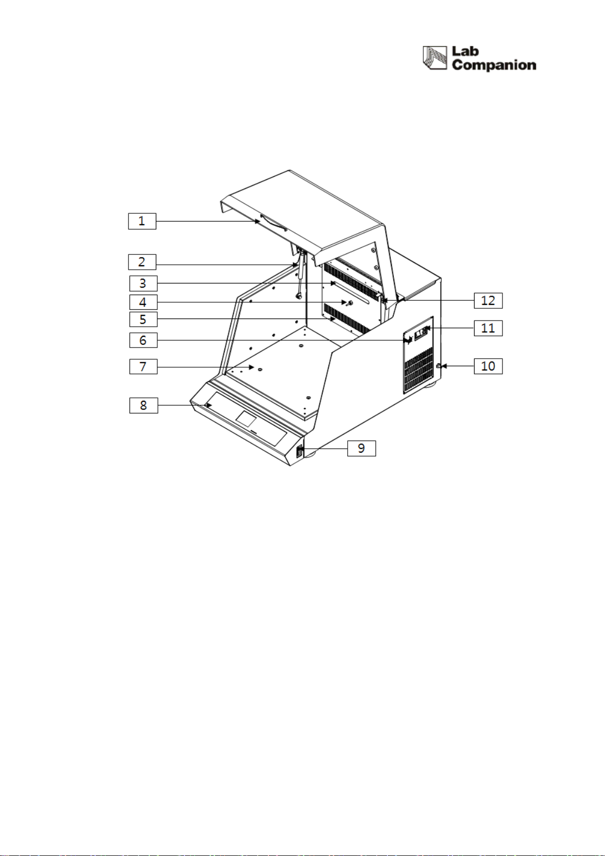
2.3 Structure
(1) Door cover and Handle
You can monitor the inner samples without opening the door during operation.
(2) Gas Spring
Door can stay opened for the user’ convenience when sample replacement.
(3) LED Lamp
Long lasting less electricity consumption LED is installed to check the inside of the chamber.
(4) Temperature Sensor
It is Pt 100Ω sensor that temperature and resistance values are shown as the linear format
and response speed is fast.

11
(5) Heater
Temperature control is up to 80℃by two 400W pin heaters.
(6) Over Temperature Limiter
Over temperature limiter is independently configured from the main controller. The inner
temperature of the chamber exceeds more than the set temperature, the device cut off the
power to the power switch for the secure condition. (Refer to ‘4.5 Safety Device’)
(7) Shaking Table
Shaking table is connected to a shaking system and Accessory such as Universal Platform
can be equipped on shaking table.
(8) Control Panel
There are independent displays for each Temperature, RPM, Timer and there are and
start/stop buttons and LED on/off buttons.
(9) Computer Interface
The unit can be controlled by PC through USB port and RS-232 port. In the case
of connecting both of the port, the USB port will be priority.
(10) Condensate Drain Barb
In case of the liquid leakage caused by spilled reagent or cracked flask inside of the chamber,
the liquid is designed to be drained out through the drain of the unit. The drain barb is
made of chromium plated copper and it is easy to connect 6mm ID soft-walled tubing to the
condensate drain. (Refer to ‘3.5 Attaching Condensate Drain’)
(11) Power Switch and Fuse
Power switch provide the main power to the device. Fuse protects the device from
instantaneous overcurrent. In case of fuse replacement, check the rated power. (Refer to 5.4

12
Fuse Replacement)
(12) Door Switch
There is a door limit switch between the door and the appliances mainframe’s upper parts. If
the door is opened, Shaking, Blower and Heater operation automatically stops. After 3
minutes at this status, warning sound alarms users to close the door. If a user does not shut
a door so that five minutes passes, and an alarm sound continuously rings. And it blocks off
the power to be authorized with a power switch, and Off gets a power switch done and all
blocks off 2 phase of the power supplied with to an each part of appliances, and
configuration does the safe state that only a Ground part is connected.
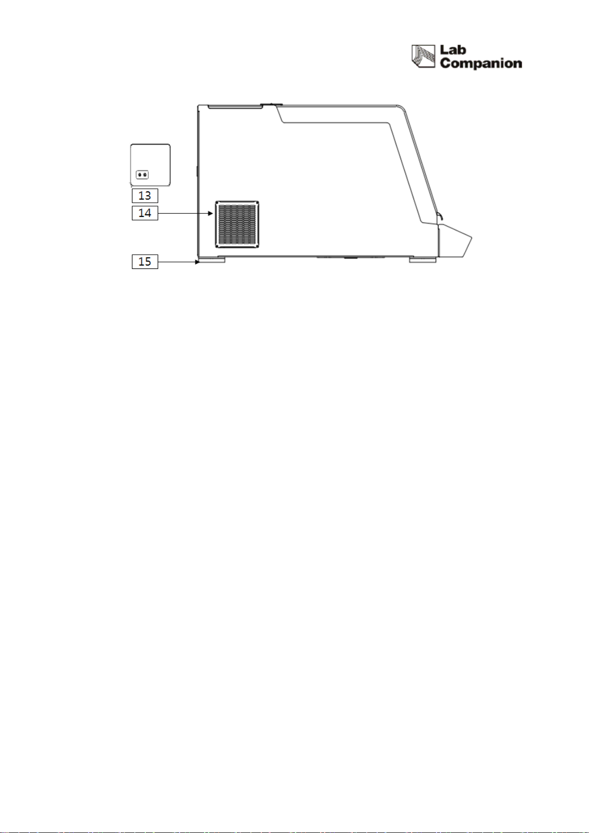
(13) External Refrigeration Port (IST-3075/IST-4075only)
Even if the model such as IST-3075/4075 which has no refrigerator, It can lower the
temperature in the chamber by receiving refrigerant from the external refrigerant device such
as chiller. The In/out ports are located on the back and bottom side of the device. These
brass push-to-connect fittings accept Ø8mm OD hard-wall tubing and provide access ports
for external refrigeration. (Refer to ‘3.6 Connection to External Refrigeration System’)
(14) Condenser Cover and Filter (IST-3075R/IST-4075R only)
Attachable condenser cover and filter prevent dust to the inside system.
(15) Foot
Foot fix the device for stable operation.
13
14
3Installation
3.1 Unpacking and Checking
(1) Inspect the shipping container carefully for any damage.
(2) Remove the outer container.
(3) Before use, inspect the product carefully for any damage that may have occurred
during shipping.
(4) Report any damage to your local Jeio Tech office or the distributor.
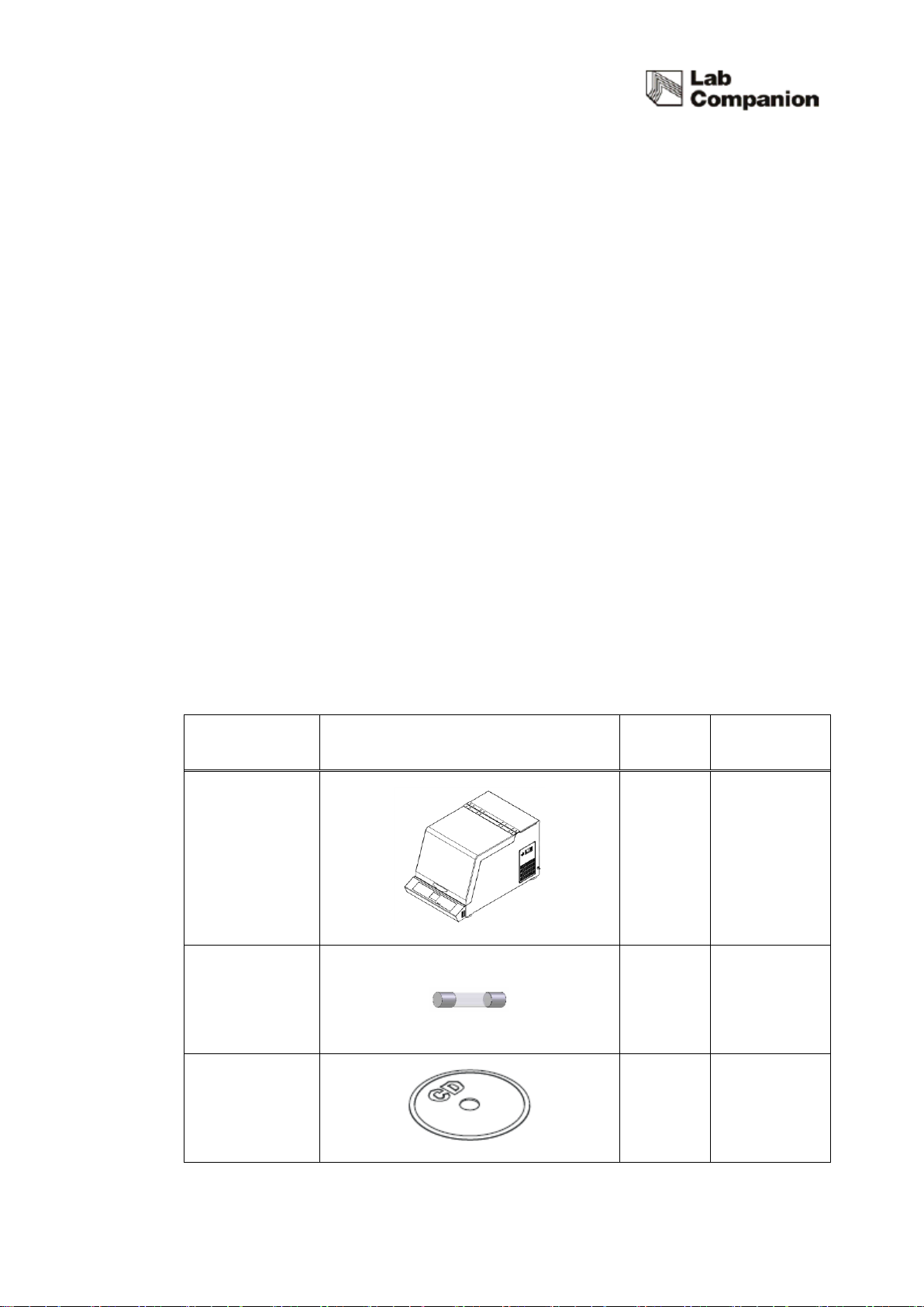
3.2 Component
(1) After unpacking, check the components.
(2) In the case of omission of components, contact to Jeiotech.
Item
Figure
Quantity
Description
Main Body
1
Fuse
2
JEIOTECH
SOFTWARE CD
1
This manual suits for next models
3
Table of contents


