ST STEVAL-IOD04KT1 User manual

Introduction
STSW-IOD04K is a software package, which lets you enable IO-Link communication between STEVAL-IOD004V1 (included in
the STEVAL-IOD04KT1 but not available for separate sale) and an IO-Link master, through the L6364W transceiver.
Based on the STM32CubeHAL, the STSW-IOD04K extends STM32Cube. It provides a board support package (BSP) for
IO-Link communication based on a demo-stack library that manages data coming from the internal L6364W temperature sensor
and the two on-board MEMS industrial sensors: IIS2MDC (high accuracy, ultra-low-power, 3-axis digital output magnetometer)
and ISM330DHCX (always-on 3D accelerometer and 3D gyroscope).
The architecture of this application software facilitates the integration with other STM32Cube-based software to create examples
for the most common application technologies. Included libraries enable functions for a real and usable system for developers.
Hardware drivers and abstract low-level details allow the middleware components and applications to access data in a
hardware-independent manner.
The middleware libraries include an ST proprietary IO-Link demo-stack.
You can use the STSW-IOD04K software package in different integrated development environments (IDEs): IAR, Keil, and
STM32CubeIDE. It also includes the IODD file to be uploaded onto the user's IO-Link master.
Getting started with the STSW-IOD04K software pack for STEVAL-IOD04KT1
dual IO-Link industrial sensor node
UM2943
User manual
UM2943 - Rev 1 - October 2021
For further information contact your local STMicroelectronics sales office.
www.st.com

1Getting started
1.1 Overview
STSW-IOD04K expands STM32Cube functionality.
The software package enables the IO-Link data transfer of industrial sensors on the STEVAL-IOD004V1 towards
an IO-Link master connected through an IO-Link connection.
The key package features are:
• Firmware package to build IO-Link device applications based on the STM32G071EB microcontroller
• Middleware libraries featuring IO-Link device demo-stack for L6364W to manage IIS2MDC and
ISM330DHCX MEMS sensors
• Ready-to-use binary for IO-Link device sensor data transmission
• Easy portability across different MCU families, thanks to STM32Cube
• Free, user-friendly license terms
1.2 Architecture
The application software accesses the STEVAL-IOD004V1 through the following software layers:
•STM32Cube HAL layer, which provides a simple, generic, multi-instance set of application programming
interfaces (APIs) to interact with the upper application, library, and stack layers. It has generic and extension
APIs and is directly built around a generic architecture. It allows successive layers like the middleware layer
to implement functions without requiring specific hardware configurations for a given microcontroller unit
(MCU). This structure improves library code reusability and guarantees an easy portability on other devices.
•Board Support Package (BSP) layer, which supports all the peripherals on the board except the MCU. This
limited set of APIs provides a programming interface for certain board-specific peripherals like the LED, the
user button, etc. This interface also helps in identifying the specific board version.
Figure 1. STSW-IOD04K software architecture
Applications &
demonstrations STSW-IOD04K
Hardware Abstraction
Layer
MEMs Manager
Middleware
Hardware
Abstraction
Hardware
STEVAL-IOD004V1
L6364W
STM32G071EB
IO-Link Stack
IIS2MDC ISM330DHCX
UM2943
Getting started
UM2943 - Rev 1 page 2/13

1.3 Folders
Figure 2. STSW-IOD04K folder structure
The software package includes the following folders:
•Documentation: a compiled HTML file generated from the source code detailing the software components
and APIs (one for each project).
•Drivers: HAL drivers and board-specific drivers for each supported board or hardware platform, including
those for the on-board components, and the CMSIS vendor-independent hardware abstraction layer for the
ARM Cortex-M processor series.
•Middlewares: libraries and protocols featuring IO-Link mini-stack and sensors management.
•Projects: sample application implementing an industrial IO-Link multi-sensor node. This application is
provided for the STM32G071EB microcontroller for three development environments: IAR Embedded
Workbench for ARM, RealView Microcontroller Development Kit (MDK-ARM-STR) and STM32CubeIDE.
1.4 APIs
Detailed technical information with full user API function and parameter description are in a compiled HTML file in
the “Documentation” folder.
1.5 Sample application description
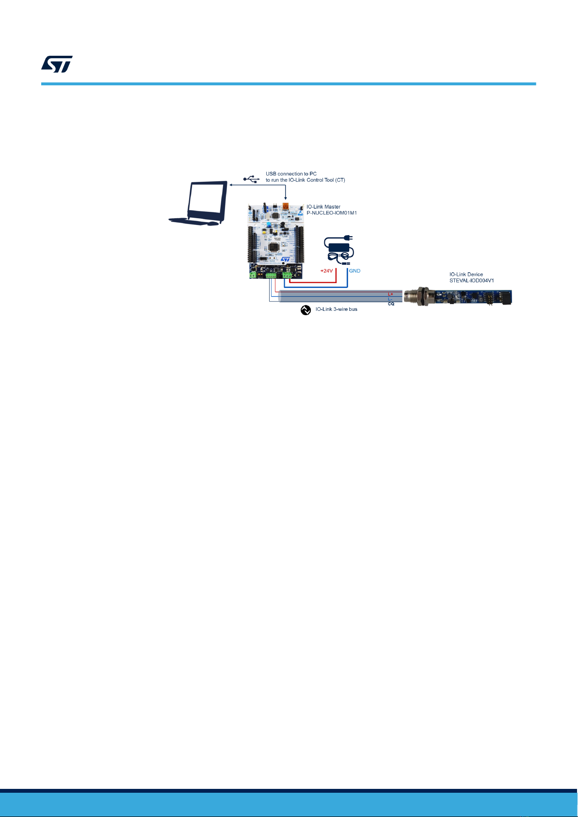
The Projects folder provides the sample application, which uses the STEVAL-IOD004V1 with the L6364W
transceiver, and the ISM330DHCX/IIS2MDC industrial sensors.
Ready-to-build projects are available for multiple IDEs. You can upload one of the binary files of the STSW-
IOD04K through STM32CubeProgrammer or the programming feature of your IDE.
To power the STEVAL-IOD004V1 and flash the firmware, you can choose one of the options below:
• Connect your MCU programmer (for example, STLINK-V3MINI) to the board through connector J1; power
up the board by the 24 V supplied from an IO-Link master; on your programmer, select the binary file to flash
and then proceed programming the MCU.
Note: For the above procedure, you need two USB ports (one for the programmer, the other for the IO-Link master).
• Connect your MCU programmer (for example, STLINK-V3MINI) to the board through connector J1; supply
the MCU by a 3.3 V power supply connected to the board through J2 (pin 2 = GND; pin 4 = 3.3 V); on your
programmer, select the binary file to flash and then program the MCU.
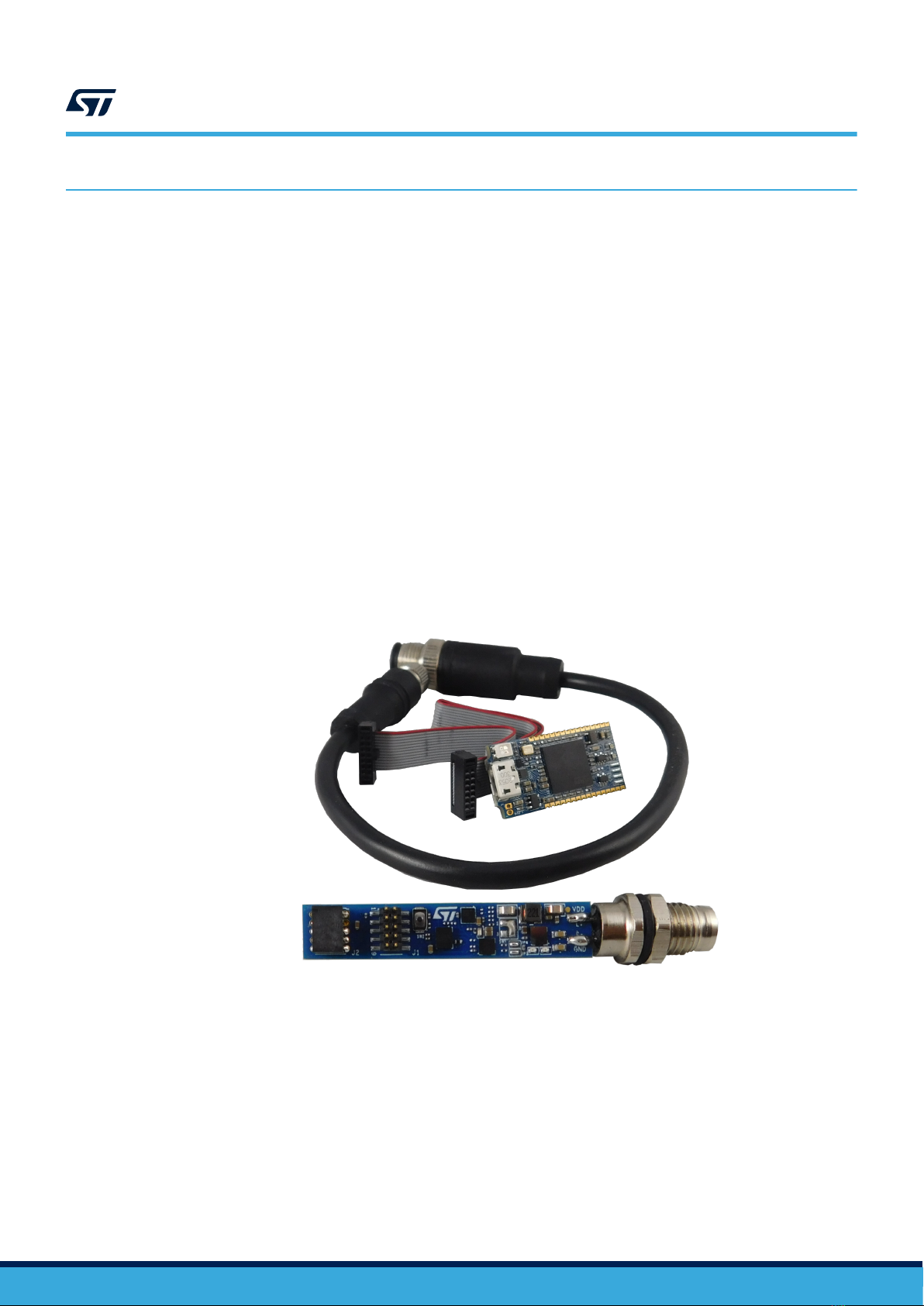
The STLINK-V3MINI programmer can be connected to the STEVAL-IOD004V1 by J1 (10 ways, two rows) through
the 14-pin flat cable included in the kit: two pins on the right and left sides of the cable remain unconnected.
Looking at the board top side and leaving the IO-Link M8 connector on your right, the cable must be connected so
that the red line is on the top, as shown below.
UM2943
Folders
UM2943 - Rev 1 page 3/13

Figure 3. STEVAL-IOD004V1 and STLINK-V3MINI - connection diagram
2 Not TOP VIEW
STEVAL-IOD004V1
connected pins
M8 IO-Link
Connector Side
2 Not
STEVAL-IOD004V1 10
pin connector
cable
STLINK-V3MINI
STLINK-V3MINI
14 pin connector
connected pins
To evaluate the STSW-IOD04K firmware, upload the IODD file on the control tool of your IO-Link master and
connect it to the STEVAL-IOD004V1 by the IO-Link cables and adapters included in the kit, or by any other
compatible cable.
You can use any other IO-Link master v1.1 with the related control tool. In the example of Section 2.2, the
IO-Link master is the P-NUCLEO-IOM01M1, the related control tool is the IO-Link Control Tool developed by
TEConcept (ST partner) and the connection is completed by an M12 socket to free wire cable (Katlax p/n
CBF12-S44N0-1.5BPUR).
UM2943
Sample application description
UM2943 - Rev 1 page 4/13

2System setup guide
2.1 Hardware description
2.1.1 STEVAL-IOD04KT1 evaluation kit
The STEVAL-IOD04KT1 is a reference design kit that exploits the features of the L6364W IO-Link dual-channel
device transceiver.
The kit consists of the STEVAL-IOD004V1 main board (not available for sale), the STLINK-V3MINI programmer
and debugger tool, a 14-pin flat cable, and an M8 to M12 standard industrial connector adapter.
The kit acts as a modern smart industrial sensor to be connected to a master IO-Link hub (or a suitable PLC
interface).
The power supply for the MCU, sensors, and other logic devices derives from the DC-DC converter controller
embedded in the L6364W.
The on-board STM32G071EB microcontroller runs an IO-Link demo stack v.1.1, which controls the IO-Link
communication, and the software code that manages the L6364W transceiver and the MEMS industrial sensors.
The tiny dimensions of the main board have been achieved thanks to the small sizes of the CSP package options
of L6364W and STM32G071EB.
Connect the main board to an IO-Link master via the adapter and the M8 connector included in the kit for normal
operation. Connect the same board to the STLINK-V3MINI through the flat cable only if you want to program the
STM32G071EB with a new firmware.
Figure 4. STEVAL-IOD04KT1 evaluation kit
STEVAL-IOD004V1
M8 to M12 cable
ST-LINKV3MINI
14-pin cable
2.2 Hardware setup
The following steps explain how to control the STEVAL-IOD004V1 through the P-NUCLEO-IOM01M1.
Step 1. Connect the P-NUCLEO-IOM01M1 to the STEVAL-IOD004V1 through three wires (L+, L-/GND, and
CQ).
The STEVAL-IOD04KT1 includes an M8 (four-way socket) to M12 (five-way plug) connector to easily
interface the STEVAL-IOD004V1 to any IO-Link master with an M12 (socket) connector.
The easiest way to connect the STEVAL-IOD004V1 to the P-NUCLEO-IOM01M1 is to use a cable with
M12 (four- or five-way socket) on one side and free wires on the other side (for example, Katlax p/n
CBF12-S44N0-1.5BPUR).
UM2943
System setup guide
UM2943 - Rev 1 page 5/13

Step 2. Connect the P-NUCLEO-IOM01M1 to a 24 V/1 A power supply.
The following figure shows how to connect the P-NUCLEO-IOM01M1 and the STEVAL-IOD004V1
running the STSW-IOD04K.
Figure 5. Terminal settings
Step 3. Launch IO-Link Control Tool on your laptop/PC.
Step 4. Connect the P-NUCLEO-IOM01M1 by mini-USB cable to your laptop/PC running the IO-Link Control
Tool.
Note: The steps from 5 to 13 refer to actions to perform in the IO-Link Control Tool.
Step 5. In the IO-Link Control Tool, click on [Select device] and follow the instructions to
upload STMicroelectronics-STEVAL-IOD004V1-38kBd-20210429-IODD1.1.xml or STMicroelectronics-
STEVAL-IOD004V1-230kBd-20210429-IODD1.1.xml, according to COM2 or COM3 choice, in the
IODD directory of the software package.
Step 6. Connect the master by clicking on the green icon (top-left corner).
Step 7. Click on [Power ON] to supply the STEVAL-IOD004V1.
The red LED on the STEVAL-IOD004V1 blinks.
Step 8. Click on [IO-Link] to initiate IO-Link communication.
The green LED on the STEVAL-IOD004V1 blinks.
Note: By default, the communication starts with ISM330DHCX configured as accelerometer.
Step 9. Plot the data collected by the ISM330DHCX accelerometer by clicking on [Plot].
UM2943
Hardware setup
UM2943 - Rev 1 page 6/13

Step 10. To activate the data exchange with another sensor, go to [Parameter Menu]>[Process Input
Selection].
Step 10a. Double-click on the sensor name (green text).
Step 10b. Select the desired sensor from the available choices.
Step 10c. Click on [Write Selected] to align the master and device.
The procedure is completed when the name of the selected sensor becomes green, as shown below.
Figure 6. IO-Link Control Tool view (example)
Figure 7. IO-Link Control Tool view - process data plot
When you finish your evaluation session, follow the additional steps below.
Step 11. Click on [Inactive] to stop IO-Link communication.
Step 12. Click on [Power Off] to stop the IO-Link master from supplying the IO-Link device.
Step 13. Click on [Disconnect] to stop the communication between IO-Link Control Tool and P-NUCLEO-
IOM01M1.
Step 14. Disconnect the mini-USB cable from the P-NUCLEO-IOM01M1.
Step 15. Disconnect the 24 V supply from the P-NUCLEO-IOM01M1.
UM2943
Hardware setup
UM2943 - Rev 1 page 7/13

2.3 Software setup
To set up a suitable development environment for the creation of IO-Link applications for the STM32G071EB and
L6364W, you need:
•STSW-IOD04K firmware and related documentation available on www.st.com;
• one of the following developments toolchain and compilers:
– IAR Embedded Workbench for ARM® toolchain
– Keil
–STM32CubeIDE plus ST-LINK/V2
UM2943
Software setup
UM2943 - Rev 1 page 8/13

Revision history
Table 1. Document revision history
Date Revision Changes
27-Oct-2021 1 Initial release.
UM2943
UM2943 - Rev 1 page 9/13

Contents
1Getting started ....................................................................2
1.1 Overview .....................................................................2
1.2 Architecture ...................................................................2
1.3 Folders .......................................................................3
1.4 APIs .........................................................................3
1.5 Sample application description ...................................................3
2System setup guide................................................................5
2.1 Hardware description ...........................................................5
2.1.1 STEVAL-IOD04KT1 evaluation kit............................................5
2.2 Hardware setup ................................................................5
2.3 Software setup.................................................................8
Revision history ........................................................................9
List of tables ..........................................................................11
List of figures..........................................................................12
UM2943
Contents
UM2943 - Rev 1 page 10/13

List of figures
Figure 1. STSW-IOD04K software architecture.....................................................2
Figure 2. STSW-IOD04K folder structure .........................................................3
Figure 3. STEVAL-IOD004V1 and STLINK-V3MINI - connection diagram ..................................4
Figure 4. STEVAL-IOD04KT1 evaluation kit .......................................................5
Figure 5. Terminal settings...................................................................6
Figure 6. IO-Link Control Tool view (example) .....................................................7
Figure 7. IO-Link Control Tool view - process data plot ...............................................7
UM2943
List of figures
UM2943 - Rev 1 page 12/13

IMPORTANT NOTICE – PLEASE READ CAREFULLY
STMicroelectronics NV and its subsidiaries (“ST”) reserve the right to make changes, corrections, enhancements, modifications, and improvements to ST
products and/or to this document at any time without notice. Purchasers should obtain the latest relevant information on ST products before placing orders. ST
products are sold pursuant to ST’s terms and conditions of sale in place at the time of order acknowledgement.
Purchasers are solely responsible for the choice, selection, and use of ST products and ST assumes no liability for application assistance or the design of
Purchasers’ products.
No license, express or implied, to any intellectual property right is granted by ST herein.
Resale of ST products with provisions different from the information set forth herein shall void any warranty granted by ST for such product.
ST and the ST logo are trademarks of ST. For additional information about ST trademarks, please refer to www.st.com/trademarks. All other product or service
names are the property of their respective owners.
Information in this document supersedes and replaces information previously supplied in any prior versions of this document.
© 2021 STMicroelectronics – All rights reserved
UM2943
UM2943 - Rev 1 page 13/13
Table of contents
Other ST Accessories manuals
Popular Accessories manuals by other brands

BS Bodensteckdosen Systemtechnik
BS Bodensteckdosen Systemtechnik 89 B Series instruction manual

UPPAbaby
UPPAbaby Ub XTEND manual

Philips
Philips P-5561-D Specifications

Lucky Reptile
Lucky Reptile Thermo Socket PRO operating instructions

Woody Valley
Woody Valley Wani light 2 owner's manual

PCB Piezotronics
PCB Piezotronics IMI SENSORS 080A122 Installation and operating manual