Jenn-Air JJB6424HM0 User manual

INSTALLATION INSTRUCTIONS
24" (59.5 CM) BUILT-IN COFFEE SYSTEM
INSTRUCTIONS D’INSTALLATION
SYSTÈME INFUSEUR À CAFÉ INTÉGRÉ DE 24" (59,5 CM)
Table of Contents/Table des matières
W11328306A
BUILT-IN COFFEE SYSTEM SAFETY ...........................................2
INSTALLATION REQUIREMENTS.................................................3
Tools and Parts.............................................................................3
Location Requirements................................................................3
Electrical Requirements ...............................................................4
INSTALLATION INSTRUCTIONS...................................................5
Install the Mounting Brackets ......................................................5
Install the Coffee System .............................................................6
Complete Installation ...................................................................6
SÉCURITÉ DU SYSTÈME INFUSEUR À CAFÉ INTÉGRÉ...........7
EXIGENCES D’INSTALLATION .....................................................8
Outillage et pièces........................................................................8
Exigences d’emplacement...........................................................8
Spécications électriques............................................................9
INSTRUCTIONS D’INSTALLATION.............................................10
Installation des platines de montage.........................................10
Installation du système infuseur à café .....................................11
Achever l’installation ..................................................................11
IMPORTANT:
Save for local electrical inspector's use.
IMPO
RTANT :
À conserver pour consultation par l'inspecteur local des installations électriques.
07-Mar-2019 02:29:19 EST | RELEASED In some European factories the letter "W" of the part code mentioned herein will be automatically
replaced by the number "4000" (e.g. "W12345678" becomes "400012345678")

2
BUILT-IN COFFEE SYSTEM SAFETY
07-Mar-2019 02:29:19 EST | RELEASED In some European factories the letter "W" of the part code mentioned herein will be automatically
replaced by the number "4000" (e.g. "W12345678" becomes "400012345678")

3
INSTALLATION REQUIREMENTS
Tools and Parts
Tools Needed
Gather the required tools and parts before starting installation.
Read and follow the instructions provided with any tools listed
here.
■Measuring tape
■Pencil
■Level
■Masking tape
■T20®† Torx®† screwdriver
■Drill
■1/16" (2 mm) drill bit
Parts Supplied
All of the following parts are provided, but some parts may not
be used. The location of your coffee system installation will
determine which parts you will use.
Location Requirements
IMPORTANT: Observe all governing codes and ordinances.
■Cabinet opening dimensions that are shown must be used.
Given dimensions provide minimum clearance with coffee
system.
■The built-in coffee system must be installed in cabinetry with
the dimensions provided.
■Follow the installation instructions for any cabinetry used
to house the built-in coffee system. Make sure cabinet is
securely attached to the wall.
■Follow the installation instructions.
■Grounded electrical supply is required. See “Electrical
Requirements” section.
■Refer to installation instructions for cutout dimensions for
any appliances installed above or below the built-in coffee
system.
IMPORTANT: To avoid damage to your cabinets, check with
your builder or cabinet supplier to make sure that the materials
used will not discolor, delaminate or sustain other damage.
This coffee system has been designed in accordance with the
requirements of UL and CSA International and complies with the
maximum allowable wood cabinet temperature of 194°F (90°C).
Product Dimensions
B
CD
E
F
A
A. Mounting brackets/runners (2)
B. Metal trim piece (1)
C. Bracket spacers (4)
(1 mm thick)
D. Power supply cord clip (1)
E. 3/16" x 5/8" (4.5 x 16 mm)
T20 screws (17)
F. 3/16"x3/8" (4.2 x 9.5 mm)
T20 screws (2)
23⁷/₁₆" ±¹/₁₆"
(59.5 ± 0.1 cm)
17⁷/₈" ± ¹/₁₆"
(45.4 ± 0.1 cm)
¹³/₁₆" ± ¹/₁₆"
(2.0 ± 0.1 cm)
18³/₁₆" ± ¹/₁₆"
(46.1 ± 0.1cm)
16⁷/₈"
(42.9 cm)
21⁷/₁₆"
(54.5 cm)
1³/₁₆"
(3.0 cm)
†Torx and T20 are trademarks of Acument Intellectual Properties, LLC.
07-Mar-2019 02:29:19 EST | RELEASED In some European factories the letter "W" of the part code mentioned herein will be automatically
replaced by the number "4000" (e.g. "W12345678" becomes "400012345678")

4
Cabinet Dimensions
*Venting cutout suggested, not mandatory.
Cutout Top View
Electrical Requirements
IMPORTANT: The coffee system must be electrically grounded
in accordance with local codes and ordinances, or in the
absence of local codes, with the National Electrical Code, ANSI/
NFPA 70 or Canadian Electrical Code, CSA C22.1.
If codes permit and a separate ground wire is used, it is
recommended that a qualied electrical installer determine that
the ground path is adequate.
A copy of the above code standards can be obtained from:
National Fire Protection Association
1 Batterymarch Park
Quincy, MA 02169-7471
CSA International
8501 East Pleasant Valley Road
Cleveland, Ohio 44131-5575
■A 120 V, 60 Hz, AC only, 15 A fused, electrical circuit
is required. A time-delay fuse or circuit breaker is also
recommended. It is recommended that a separate circuit
serving only this coffee system be provided.
■Check that the outlet provides 120 V power and is correctly
grounded.
1¹¹/₁₆"
(4.3 cm)*
1¹¹/₁₆"
(4.3 cm)
1¹¹/₁₆"
(4.3 cm)
19⁵/₈"
(50 cm)
21⁷/₁₆" Min.
17¹¹/₁₆" + 1/16"
(45 + 0.17 cm)
33⁷/₁₆" Min.
(85 cm)
22¹/₁₆"
(56 cm)
G
ABCDEF
(38.2 cm)
15¹⁄₈"
14³⁄₈"
(36.1 cm)
(44.8 cm)
17⁵⁄₈"
(40.1 cm)
15¹⁵⁄₁₆"
A. Coffee system
B. Non-flush receptacle
C. Flush receptacle
D. Back of cabinet
E. Non-flush receptacle located in upper right
or upper left corner
F. Wall behind cabinet
G. Coffee system with runners fully extended
Electrical Shock Hazard
Plug into a grounded 3 prong outlet.
Do not remove ground prong.
Do not use an adapter.
Do not use an extension cord.
Failure to follow these instructions can result in death,
fire, or electrical shock.
WARNING
07-Mar-2019 02:29:19 EST | RELEASED In some European factories the letter "W" of the part code mentioned herein will be automatically
replaced by the number "4000" (e.g. "W12345678" becomes "400012345678")

5
INSTALLATION INSTRUCTIONS
Install the Mounting Brackets
1. Determine where the mounting brackets will be installed and
mark 6 holes through each mounting bracket onto the side
cabinet.
IMPORTANT: The front of the mounting bracket must be
1/16" (2 mm) from the outside of the cabinet frame.
NOTE: To accommodate for ush installation with certain
custom cabinets, align the front of the mounting brackets
13/16" (2.1 cm) back from the front of the cabinet.
2. With the mounting brackets held or taped in place,
measure the distance between the two brackets. (Do not
measure between the runners.) The distance should be
21¹¹⁄zn"(55.1cm).
NOTE: If the distance between the mounting brackets is
greater than 22" + 1⁄16" (55.9 + 0.07 cm), bracket spacers
will need to be used. Four 1 mm bracket spacers are
included. See Step 3.
3. If bracket spacers are needed: Position the necessary
spacer(s) behind the mounting brackets. Continue with
Step 4.
4. Using a 1/16" (2 mm) drill, drill the holes marked in Step 1.
5. Secure the mounting brackets to the side cabinets with six
3/16" x 5/8" (4.5 x 16 mm) screws in each bracket.
6. Remove the tape holding the brackets in place.
7. Pull the runners forward until they are fully extended and in
the locked position. Place level across the runners and check
levelness. Then place the level along the length of each
runner and check levelness from front to back. If the runners
are not level, uninstall the mounting brackets and raise or
lower the mounting brackets as necessary until they are
level.
8. If the coffee system is being installed above a wooden
cabinet bottom, use two 3/16" x 5/8" (4.5 x 16 mm) screws
to install the metal trim piece at the front edge of the cabinet
bottom.
A. Front of mounting bracket 1/16" (2 mm)
from outside of cabinet frame
B. Mark 6 screw holes.
1/16"(2 mm)
B
A
B
(=) (=)
A
A
22 + 1/16"
(55.9 + 0.07 cm)
A. Bracket spacers
07-Mar-2019 02:29:19 EST | RELEASED In some European factories the letter "W" of the part code mentioned herein will be automatically
replaced by the number "4000" (e.g. "W12345678" becomes "400012345678")

6
Install the Coffee System
1. Pull the runners forward until they are fully extended and in
the locked position.
2. Using 2 or more people, position the coffee system onto
the runners, making sure that the 4 pins of the L-brackets t
securely inside the holes on the bottom of the coffee system.
3. Secure the coffee system to the runners with the four
3/16"x3/8" (4.2x9.5 mm) screws.
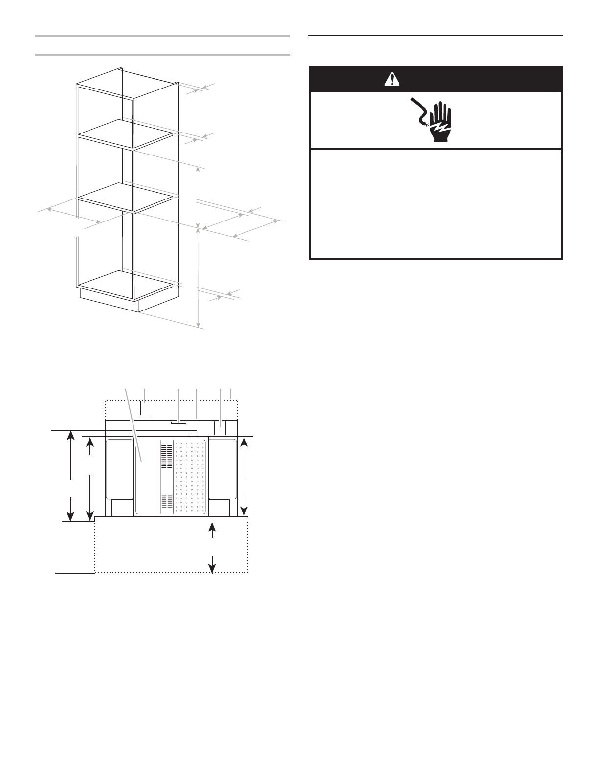
4. Position the power supply cord clip on the top of the cabinet,
approximately 13ZZ/zn" (34.8 cm) from the front of the cabinet
and centered from left to right. With a pencil, mark the hole
through the clip on the top of the cabinet.
5. Using a 1/16" (2 mm) drill, drill the hole marked in Step 4.
6. Using one 3/16" x 5/8" (4.5 x 16 mm) screw, attach the
power supply cord clip to the top of the cabinet.
7. Secure the power supply cord with the power supply cord
clip. Make sure there is enough slack in the power supply
cord to allow the coffee system to be pulled completely from
the cabinet in order to ll the coffee bean container.
8. Plug the coffee system into a grounded 3-prong outlet.
9. Push the coffee system back into the housing.
10. Proceed to “Complete Installation” section.
Complete Installation
1. Prepare your coffee system for use by following the
directions in “Before Using the Coffee System” in the Use
and Care Guide. Then test the coffee system by using one of
the coffee system functions.
2. If the coffee system does not operate:
■Check that a household fuse has not blown, or a circuit
breaker tripped. Replace the fuse or reset the circuit
breaker. If the problem continues, call an electrician.
■Check that the power supply cord is plugged into a
grounded 3 prong outlet.
■See the Use and Care Guide for troubleshooting
information.
Installation is now complete.
Save these Installation Instructions for future use.
If you need Assistance or Service:
Please reference the “Assistance or Service” section of the
Use and Care Guide, or contact the dealer from whom you
purchased your coffee system.
WARNING
Excessive Weight Hazard
Use two or more people to move and install the built-in
coffee system.
Failure to do so can result in back or other injury.
Approx. 13¹¹/₁₆"
(34.8 cm)
AB
A. Power supply cord clip
B. Power supply cord
Electrical Shock Hazard
Plug into a grounded 3 prong outlet.
Do not remove ground prong.
Do not use an adapter.
Do not use an extension cord.
Failure to follow these instructions can result in death,
fire, or electrical shock.
WARNING
07-Mar-2019 02:29:19 EST | RELEASED In some European factories the letter "W" of the part code mentioned herein will be automatically
replaced by the number "4000" (e.g. "W12345678" becomes "400012345678")
Table of contents
Other Jenn-Air Coffee Maker manuals