Jepson WRAPAROUND TUBE SANDER 760/40 User manual

Instruction Manual WRAPAROUND TUBE SANDER 760/40
Page 1 of 10
Instruction Manual
WRAPAROUND TUBE SANDER 760/40
www.drycutter.com

Instruction Manual DRUM SANDER 100
Page 2of 10
Index
1EG-Conformity Declaration ..............................2
2Specifications ....................................................2
3User Instructions...............................................3
4Safety Instructions ............................................3
4.1 Illustration of Safety Instructions .............3
4.2 General Safety Instructions ......................3
4.3 Specific Safety Rules................................5
5Functional Description .....................................5
5.1 Unpacking.................................................5
5.2 Installing the belt.......................................5
5.3 Wraparound TUBE SANDER ...................6
OPERATION: Start and Stop of the machine........6
5.4 CONTROLLING THE VARIABLE SPEED6
5.5 OPERATION............................................ 6
6Maintenance and Repair .................................. 7
6.1 Keep Tool Clean ...................................... 7
6.2 FAILURE TO START ............................... 7
6.3 Replacing Carbon Brushes ...................... 7
7Standard Accessories ...................................... 8
8Optional accessories: ...................................... 8
9Spare parts - List of Spare Parts ..................... 9
10Spare Parts Drawing....................................... 10
1 EG-Conformity Declaration
(according to Appendix IIA of the machine Directive)
We,
Routexport Agencies SA
Visserijstraat 25, rue de la Pêcherie
1180 Brüssel
Belgien
as the manufacturer declare herewith under our responsibility that the product:
Name: Wraparound Tube Sander/Polisher Machine
Serial No. :
Manufacturing Date: 2011
complies with the following standards, directives and referenced standard documents:
2006/195/EC
2004/108/EC
2006/42/EC
Low Voltage Directive
EMC Directive
Machinery Directive
EN 60745-1 :2009+A11 :2010
EN 60745-2-4 :2009+A11 :2011
EN 62233 :2008
EN 55014-1 :2006+A1 :2009+A2 :2011
EN 55014-2 :1997+A1 :2001+A2 :2008
EN 61000-3-2 :2006+A1 :2009+A2 :2009
EN 61000-3-3 :2008
Pierre Michiels, Managing Director
Name, Position Brussels, 02.01.19
2 Specifications
Voltage 230V /50 Hz
No load speed 1600-3200/min
Power input 1200W
Surface speed 3-12 m/sec
Max belt length 760 mm
Max. belt width 40 mm
Soft start and overload
protection
with
Net weight 3.4 kg

Instruction Manual WRAPAROUND TUBE SANDER 760/40
Page 3 of 10
3 User Instructions
Notes for the customer
The instruction manual includes important instructions as to how
to operate the plant safely, correctly and economically.
Observing these instructions helps to avoid risks, repair costs
and downtimes and to increase the reliability and lifetime of the
machine.
The instruction manual must be read and used by each person
who works with the electrical equipment. This applies in
particular to the "Safety Instructions" chapter. It is too late to
read the manual and safety instructions when work is actually
being carried out at the machine.
Always keep one copy of this manual next to the machine so
that it is at hand ready to be consulted!
In case of any doubt or questions, always contact the machine
manufacturer.
In addition to the instruction manual, the accident prevention
regulations which apply in the country of use and the user
location must be adhered to. In addition, the recognised
technical rules regarding accident prevention must be observed.
Liability and warranty
All the information contained in this instruction manual has been
drawn up to the best of our knowledge and belief, taking our
experience to date into consideration.
The original version of this instruction manual was drawn up in
the German language and was checked by us for accuracy of
content. The translation into the respective national/contractual
language was carried out by a recognised translation agency.
This instruction manual has been put together with the greatest
of care. However, if you should discover any incomplete items or
mistakes, please inform us in writing. Your suggestions for
improvement will help us to create a user-friendly manual.
Subsequent Orders and Copyright
Further copies of this instruction manual can be ordered from
the address below. We ask for your understanding that further
copies are subject to charge.
Jepson Power GmbH
Ernst-Abbe-Straße 5
D-52249 Eschweiler
Phone: +49 (0)2403 – 6455-0
Fax: +49 (0)2403 – 6455-15
All rights are expressly reserved. Duplication or transfer on to
third parties in any form whatsoever is not allowed without our
prior written permission.
Abbreviations
V Volt
Hz Hertz
W Watt
~ AC
/min Revolutions per minute rpm
N Newton
4 Safety Instructions
The basic prerequisite for safe handling and disturbance-free
operation of this electric tool is knowledge of the basic safety
instructions. In addition, the accident prevention rules and
regulations which apply in the user location must be adhered to,
as well as the recognised rules of the trade with regard to safety
and correct working methods.
It is not permitted to use the electric tool for other purposes than
those intended by the manufacturer. Such use could give rise to
unforeseeable risks.
Local working and safety rules and laws must always be
followed. The same applies to regulations which apply to the
environment.
Safety equipment must never by removed or bridged over.
When using oils, greases and other chemical substances, the
safety regulations which apply to the particular product must
always be observed! Contact with chemicals should be avoided
as far as possible. Before it is permissible to work with these
substances the instructions for use on the packaging must be
read and followed. This applies for all chemicals, therefore also
for cleaning media.
All notes and signs regarding safety and possible risks must be
kept in a fully legible condition.
4.1 Illustration of
Safety Instructions
The following symbols are used in the instruction manual:
Warning against possible danger of injury or
danger to life for persons
Warning
Warning against possible damage to property or
the environment
Caution
Warning against dangerous electrical voltage
Warning against hot surfaces
Ignoring these instructions can lead to serious damage to
health, up to life-threatening injuries!
This symbol indicates important information
Hazardous to the environment
4.2 General Safety Instructions
This electric tool fulfils the basic EC safety
and health regulations. Nevertheless,
dangerous situations can arise.
Warning
All safety equipment must be maintained in
perfect condition.
Warning
Always pay attention to moving parts.
These can cause injury because of their
movement or by sudden movement.
Warning

Instruction Manual WRAPAROUND TUBE SANDER 760/40
Page 4 of 10
Only use the electric tool when it is in
perfect condition from the technical point
of view, and only use it for intended
purpose while being aware of safety
issues and risks, and paying attention to
the instruction manual! In particular,
have any disturbances which could have
a negative effect on safety corrected
immediately!
WARNING! It is essential to read all the instructions.
Mistakes which are made while attempting to follow the
below instructions can cause electric shock, fire and/or
serious injury. The following term "Electric tool", refers to
mains-powered electric tools (with mains cable) and
battery-powered electric tools (without mains cable).
Warning Caution
KEEP THESE INSTRUCTIONS IN A SAFE
PLACE.
Work Area Safety
Keep your work area clean and well lit. Cluttered benches
and dark areas invite accidents.
Do not operate power tools in explosive atmospheres, such
as in the presence of flammable liquid, gases, or dust.
Power tools create sparks, which may ignite the dust or fumes.
Keep bystanders, children, and visitors away while
operating a power tool. Distractions can cause you to lose
control.
Electrical Safety
Warning Caution
Earthed tools must be plugged into an outlet properly
installed and earthed in accordance with all codes and
ordinances. Never remove the earthing prong or modify the
plug in any way. Do not use any adaptor plugs. Check with
a qualified electrician if you are in doubt as to whether the
outlet is properly earthed. If the tools should electrically
malfunction or break down, earthing provides a low resistance
path to carry electricity away from the user.
Avoid body contact with earthed or grounded surfaces
such as pipes, radiators, ranges and refrigerators. There is
an increased risk of electric shock if your body is earthed or
grounded.
Don’t expose power tools to rain or wet conditions. Water
entering a power tool will increase the risk of electric shock.
Don’t abuse the cord. Never use the cord to carry the tools
or pull the plug from an outlet. Keep cord away from heat,
oil, sharp edges or moving parts. Replace damaged cords
immediately. Damaged or entangled cords increase the risk of
electric shock.
When operating a power tool outside, only use authorized
cords for outdoor work. These cords are rated for outdoor use
and reduce the risk of electric shock.
Personal Safety
Stay alert, watch what you are doing and use common sense
when operating a power tool. Do not use tool while tired or
under the influence of drugs, alcohol, or medication. A
moment of inattention while operating power tools may result in
serious personal injury.
Use safety equipment. Always wear eye protection. Safety
equipment such as dust mask, non-skid safety shoes, hardhat, or
hearing protection used for appropriate conditions will reduce
personal injuries.
Avoid accidental starting. Be sure switch is off before
plugging in. Carrying tools with your finger on the switch or
plugging in tools that have the switch on invites accidents..
Warning Caution
Remove any adjusting key or wrenches before turning the
tool on. A wrench or a key that is left attached to a rotating part
of the tool may result in personal injury.
Do not overreach. Keep a proper footing and balance at all
times. Proper footing and balance enables better control of the
tool in unexpected situations.
Dress properly. Do not wear loose clothing or jewellery.
Keep your hair, clothing and gloves away from moving
parts. Loose clothes, jewellery or long hair can be caught in
moving parts.
Tool use and care
Use clamps or other practical way to secure and support
the work piece to a stable platform. Holding the work by
handor against your body is unstable and may lead to loss of
control.
Do not force tool. Use the correct tool for your application.
The correct tool will do the job better and safer at the rate for
which it is designed.
Do not use tool if switch does not turn it on and off. Any tool
that cannot be controlled with the switch is dangerous and must
be repaired.
Disconnect the plug from the power source before making
any adjustments, changing accessories, or storing the tool.
Such preventive safety measures reduce the risk of starting the
tool accidentally.
Store idle tools out of reach of children and do not allow
persons unfamiliar with the power tool or these instructions
to operate the power tool. Tools are dangerous in the hands of
untrained users.
Maintain tools with care. Keep cutting tools sharp and
clean. Properly maintained tools, with sharp cutting edges are
less likely to bind and are easier to control.
Maintain power tools. Check for misalignment or binding of
moving parts, breakage of parts, and any other condition
that may affect the tools operation. If damaged, have the
tool serviced before using. Poorly maintained tools cause
many accidents.
Use the power tool, accessories and blades etc., in
accordance with these instructions and in the manner
intended for the particular type of power tool, taking into
account the working conditions and the work to be
performed. Use of the power tool for operations different from
those intended could result in a hazardous situation.
Use only accessories that are recommended by the
manufacturer for your model. Accessories that may be
suitable for one tool may become hazardous when used on
another tool.
Instruction Manual WRAPAROUND TUBE SANDER 760/40
Page 5 of 10
Warning Caution
Service
Only qualified repair personnel must perform tool service.
Service or maintenance performed by unqualified personnel
could result in a risk of injury.
When servicing tool, use only identical replacement parts.
Follow instructions in the Maintenance section of this manual.
Use of unauthorized parts or failure to follow Maintenance
Instructions may create a risk of electric shock or injury.
4.3 Specific Safety Rules
Never operate the tool in an area with flammable solids, liquids, or
gases. Sparks from the commutator/carbon brushes could cause a
fire or explosion.
WARNING! Risk of injury from high-
temperature chips!
High-temperature chips are expelled at high
speed. Never touch the tool holder and keep
all vulnerable body parts clear while the
machine is running.
Warning
Always guide the machine away from the body while working. Do
not work holding the machine above your head.
WARNING! Some dust created by power
grinding contains chemicals known to cause
cancer, birth defects or other reproductive harm.
Warning
An example of these chemicals are: lead from lead-based paint
Your risk from these exposures varies, depending on how often you
do this type of work. To reduce your exposure to these chemicals:
work in a well-ventilated area, and work with approved safety
equipment, such as those dust masks that are specifically designed
to filter out microscopic particles.
1. Use clamps or other practical way
to secure and support the work
piece to a stable platform. Holding
the work by hand or against your
body is unstable and may lead to
loss of control.
2. Keep hands away from rotating
parts.
3. Wear eye and hearing protection.
Always use safety glasses. Every
day eyeglasses are NOT safety
glasses. USE CERTIFIED SAFETY
EQUIPMENT.
4. Use of this tool can generate and
disburse dust or other airborne
particles including wood dust,
crystalline silica dust and asbestos
dust. Keep direct particles a way
from face and body. Always operate
tool in well ventilated area and
provide for proper dust removal. Use
dust collection system wherever
possible. Exposure to the dust may
cause serious and permanent
respiratory or other injury, including e
silicosis (a serious lung disease)
,cancer and death. Avoid breathing
the dust, and avoid prolonged
Warning
contact with dust. Allowing dust to
5 Functional Description
5.1 Unpacking
The Wraparound Tube Sander is especially designed for fast
sanding, compounding, mirror polishing and buffing of stainless
steel and aluminium open and closed tube forms. There are
different belts available in various grits. The unique feature of this
machine is its ability to contact a tubular surface and wrap around
about 180 degrees of its circumference at a time for very fast and
efficient working.
ASSEMBLY
CAUTION:
DISCONNECT TOOL FROM POWER SOURCE.
THE GUARD AND HANDLE
Warning
Place the front handle in position on the belt guard
and tighten by hand.
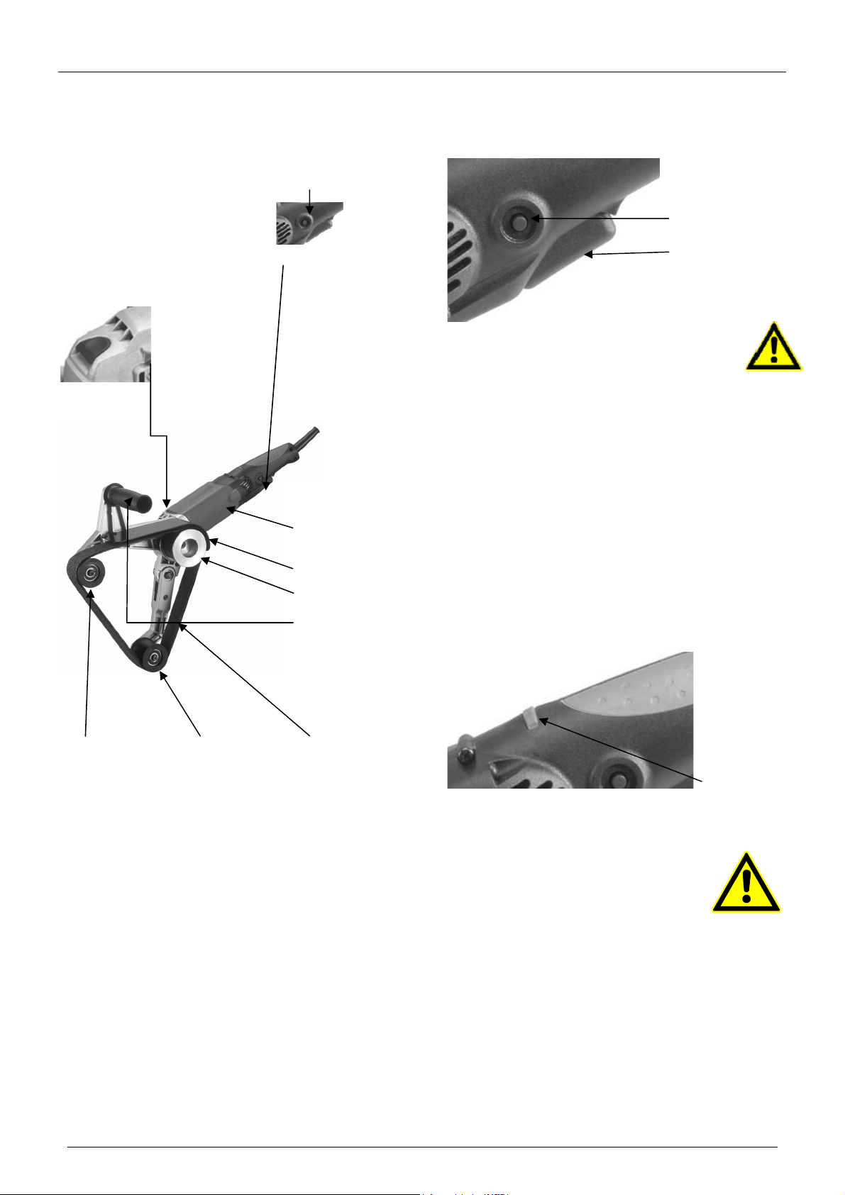
5.2 Installing the belt
1. Lay the machine so that it is upside down resting on the
front handle (with the handle parallel to the ground).
2. Loop belt around the drive pulley and the idler arm
(stationary) pulley.
3. While pushing the tensioner arm down against the spring
to create enough slack, slip the belt over the tensioner
arm pulley. Then release the arm.
WARNING: The machine should not be
converted or modified, e.g. for any other form of
use, other than as specified in these operating
instructions. The user shall be liable for
damages and accidents due to incorrect use
.
Warning
get into your mouth or eyes, or lay on your skin
may promote absorption of harmful material .
Always use properly fitting mask approved for
the dust explosure and wash exposed areas
with soap and water.
DANGER: Indicate an imminently hazardous
situation which, if not avoided, will result in
death or serious injury.
Indicates a potencially hazardous situation
which, if not avoided, could result in death
or serious injury.
CAUTION: indicates a potentially hazardous
situation which, if not Avoided, may result in
minor or moderate injury or indicates
potentially hazardous situation which, if not
Warning
Warning
Warning
Instruction Manual WRAPAROUND TUBE SANDER 760/40
Page 6 of 10
5.3 Wraparound TUBE SANDER
Do not operate this too until you read and understand the
entire instruction manual.
OPERATION: Start and Stop of the machine
Switch look
Trigger switch
CAUTION:
Make sure switch is OFF and power circuit voltage is
the same as that shown on the specification plate.
1. Connect tool to power source.
2. Grip machine firmly to resist start in torque
3. Squeeze trigger switch to turn tool on. Release the trigger
to shut tool off.
4. To lock the switch in the “on” position, press the lock pin
while the switch is fully on. To release the lock, press the
switch and release it.
5.4 CONTROLLING THE VARIABLE SPEED
The thumbwheel sets the maximum speed, while the trigger turns the
machine on and off. With switch in the locked ON position the
thumbwheel may be used to adjust the speed. This machine
incorporates feedback speed stabilization so that the speed will not
slow with load. It will maintain the present speed regardless of the
load.Always start at a slower speed and work up to the best speed.
Speed adjustment
5.5 OPERATION
WARNING: If the workpiece is not
attached to anything and is light
enough to be moved by the spinning
drum, it should be securely clamped or
anchored to prevent it being thrown or
flung, resulting in possible injury.
Warning
1. Hold the machine firmly by the front andrear handles,
making sure the drum is clear of foreign objects.
2. Start the machine and lower it to the work.
3. Move the machine in long overlapping strokes. DO NOT
HOLD TOO LONG IN ONE SPOT otherwise will overheat
the surface and cause uneven results.
4. Always be sure motor has stopped before setting the
machine down.
Guard clamp lever
Spindle lock
Idler arm pulley Tensioner Belt (optional)
arm pulley arm pulley
Trigger switch
Lock button
Motor
Guard
Drive pulley
Front handle

Instruction Manual WRAPAROUND TUBE SANDER 760/40
Page 7 of 10
When using the machine to apply products (compounds, polishes,
waxes, cleaners, etc). always read and follow the manufacturers
directions supplied with product. In this case do not run the
machine without the drum in contact with work surface. Otherwise
the media will be thrown outwards. Start and stop the machine with
the drum against work surface.
WARNING: Do not use the same belt to apply different
grades of compound. The coarser compound will
contaminate the finer compound, causing poor
results.
Warning
6 Maintenance and Repair
6.1 Keep Tool Clean
Periodically blow out all air passages with dry compressed air. All
plastic parts should be cleaned with a soft damp cloth. NEVER
use solvents to clean plastic parts. They could possibly dissolve
or otherwise damage the material. Wear safety glasses while
using compressed air.
Wear safety glasses while using compressed air.
6.2 FAILURE TO START
Should your tool fail to start, check to make sure the prongs on the
cord plug are making good contact in the outlet. Also, check for
blown fuses or open circuit breakers in the line.
6.3 Replacing Carbon Brushes
The carbon brushes are a normal wearing part and must be
replaced when they reach their wear limit.
NOTE: Checking and replacing the carbon brushes should be
entrusted to a qualified service center.
The carbon brushes furnished will last approximately 50 hours of
running time or10,000 on/off cycles. Replace both carbon brushes s
when either has less than 1 / 4 " length of carbon remaining.
To replace:
1. To inspect or replace brushes, first
unplug the machine. Carefully
remove the 8 screws to separate
the two handle halves and remove
fr om t he m ot or housing. Remove the
left handle half first.
2. There will still be wires connected to
the rear handle, so take care that
these are not stressed. Simply hold the
rear handle off to one side.
3. Next remove the two screws holding
on the Electronics Unit to allow access
to the Brush Holder screws. Hold the
Electronics Unit off to one side and
avoid stressing the wires.
4. Unscrew the two Carbon Brush Holders
in turn and remove the Carbon
Brushes.
NOTE: When putting the Carbon
Brushes back into the Carbon Brush
Holders it is essential that both
flanges go back inside the holder.
NOTE: To reinstall the same brushes ,
first make sure the brushes go back
in the same way they came out.
Otherwise a break –in period will
occur that will reduce motor
performance and increase brush
wear.
Replacing is the reverse of removal. Replace the Brush Holder
screws, then the Electronics Unit screws.
When Replacing the rear handle to the motor housing, take great
care that all wires are in place and not in a position to be pinched
when it is retightened.
It is recommended that, at least once a year, you take the tool to an
Authorized Service Center for a thorough cleaning and lubrication.
If the replacement of the power supply cord is necessary,
this has to be done by the manufacturer or their agent in
order to avoid a safety hazard.

Instruction Manual WRAPAROUND TUBE SANDER 760/40
Page 8 of 10
7 Standard Accessories
10 arbor spacer discs ( for fitting smaller wheels to the arbor)
8 Optional accessories:
Surface Conditioning belt
120 grit Sandpaper belt
Sanding Sponge Belt-Fine

Instruction Manual WRAPAROUND TUBE SANDER 760/40
Page 9 of 10
9 Spare parts - List of Spare Parts
No . Pa r t . No . QT ' Y
1.) WS001 POWER SUPPLY CABLE 0.75 x 2C x 3M 1
2.) WS002 CORD A RMOR 1
3.) WS003 CA BLE CLIP 1
4.) WS004 SCREW M4 x 14 6
5.) WS005 WIRE LEAD 1
6.) WS006 SWITCH 1
7.) WS007 SCREW M4 x 25 4
8.) WS008 RIGHT HA NDL E COV ER 1
9.) WS009 LEFT HANDLE COVER 1
10.) WS010 SCREW M4 x 20 2
11.) WS011 ELECTRONICS UNIT 1
12.) WS012 THUMB WHEEL 1
13.) WS013 BRUSH SCREW M4 x 8 2
14.) WS014 CA RBON BRUSH 2
15.) WS015 CA RBON BRUSH HOLDER 2
16.) WS016 SCREW M4 x 8 3
17.) WS017 FLAT WASHER M4 1
18.) WS018 PLASTIC WASHER φ4 x φ11 x 1 1
1 9 . ) W S0 1 9 PIC KUP MA G NET φ8 x φ15 x 5 1
20.) WS020 SPACER φ8 x φ12 x 10.5 1
21.) WS021 MOTOR HOUSING 1
22.) WS022 STATOR 220 Volt 1
23.) WS023 STATOR SCREW M4 x 60 2
24.) WS024 BALL BEARING 608-2RS 1
25.) WS025 ARMATURE 220 Volt M1.0 6T 1
26.) WS026 BALL BEARING 6000-2RS 1
27.) WS027 GEA R CA SE 1
28.) WS028 SPINDLE LOCK BUTTON 1
29.) WS029 SPRING φ0.9 x φ10 x 13.
5
1
30.) WS030 SPINDLE LOCK 1
31.) WS031 SCREW M4 x 30 4
32.) WS032 NEEDLE BEA RING HK0608 1
33.) WS033 BEVEL GEAR M1.0 46T 1
34.) WS034 GEAR PLATE 1
35.) WS035 SCREW M4 x 20 4
36.) WS036 EXTERNAL CIRCLIP S-12 1
37.) WS037 BALL BEARING 6001-2RS 1
38.) WS038 PARALLEL KEY 4 x 4 x 8 1
39.) WS039 SPINDLE 1
40 .) WS0 40 INTERNA L CIRCL IP R- 28 1
41.) WS041 FRONT HA NDLE 1
42.) WS042 IDLER ARM 1
43.) WS043 AXLE 16*17 2
44.) WS044 BALL BEARING 6200-2RS 4
45.) WS045 PULLEY 2
46.) WS046 EXTERNAL CIRCLIP S-10 2
47.) WS047 BOLT M10 x P1.5 x 12 2
48.) WS048 PIVOT BOLT M8 x P1.25 x 7.7 1
49.) WS0 49 HA IRPIN SPRING φ2.8 x φ14.5 x
4
1
50.) WS050 TENSIONER ARM 1
51.) WS051 GUARD 1
52.) WS052 SCREW M4 x 25 4
53.) WS053 DRIVE PULLEY 1
54.) WS054 SCREW M5 x 8 2
De s cr ip t i p n
Instruction Manual WRAPAROUND TUBE SANDER 760/40
Page 10 of 10
10 Spare Parts Drawing
Table of contents
Other Jepson Sander manuals


