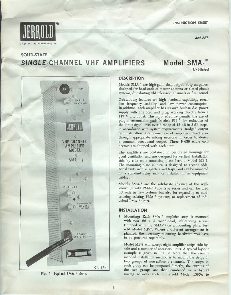
Jerrold DE-SNOWER DSS 2 Series User manual

~
ID
J~HH~ln
a GENERALINSTRUMENTcompany
,J,
INSTRUCTION SHEET
435-578-03
DE-SNOWER@SINGLE-CHANNELVHF PREAMPLIFIERS
MODELS DSS-*, SERIES 2
DESCRIPTION
Models DSS-0, Series 2 consist of preamplifiers Model 802,
factory-tuned to specific VHF -TV channels or the FM .
band, and power supply Model 105.
Models 802 are designed with three basic circuit arrange-
ments: for low-band channels, for high-band channels, and
for the FM band (see Specifications). The preamplifiers
exhibit high gain, low noise, and high overload capability.
In adjacent channel areas, traps installed between the
antennas and the preamplifiers will maintain the necessary
selectivity.
Models 802 are enclosed in a cast-aluminum housing
designed for mounting on an antenna mast with the acces-
sories supplied. Power supply Model 105 is designed for
indoor installation near a 115V a.c. outlet and delivers a
nominal 16V a.c. to the preamplifier's d.c. supply circuit
through the down lead. Input and output connections to
the equipment are made through 75-ohm F fittings.
INSTALLATION
GENERAL
For maximum benefit from the signal strength available at
the antenna and for minimum pickup of undesired signals,
mount the preamplifier as near the antenna terminal as
practicable.
ACCESSORIESSUPPLIED
1 Mounting Bracket
1 V-Bolt
2 Self-Locking Hex Nuts
1 6-32x~~"Self-Tapping Screw
2 6xJ~"Woodscrews
4 F-659 Connectors with Ferrules and Expansion Tool
2 WB-659 Weatherboots
PROCEDURE
1. Start the supplied self-tapping screw through the hole
in the wide end of the mounting bracket; enter the
screw from the side of the bracket with the hook (on
the narrow end).
2. Slip the keyhole slot in the tab on the preamplifier
housing over the screw so that the hook on the bracket
engages the slot at the opposite end of the housing;
tighten the screw.
l
rJ-- -":o*,,~,"'
.\~ . ---~"{L
~~
-- -
~\
ANT.\~
MODEL 802
PAflT OF
De-SNOWER
CHAN PREAMP
MODEL DSS-2
us!: WITH pWfl.
SUPPL Y MoDEL to!;
Fig. 1 Preamplifier,Model 802
-..----
tf..p,:,,~r
"'.:1>.. .~.
"tI,\"G
1'0 ,..~~\..\f\e.f\
Fig. 2 Power Supply, Modell 05
3. Mount the unit on the antenna mast using the V-bolt
and self-locking hex nuts supplied; the preamplifier
terminals should face down.
4. Prepare a length of Jerrold Coloraxial cable sufficient to
interconnect the antenna and the preamplifier. Slip a
weatherboot over each end of the cable and install
F-659 connectors on the ends as described in Instruc-
tion Sheet 435-650, included in the accessory package.
5. Connect the cable between the antenna and the ANT
terminal on the preamplifier. Apply a coating of sili-
cone weatherproofing compound to the connections
and slide the weatherboots over the connections.

6. Prepare a down-lead of Coloraxial cable to interconnect
the preamplifier and the power supply. Slip a weather-
boot over the preamplifier end of the cable and install
an F-659 connector.
7. Connect the cable end with the weatherboot to the
preamplifier PWR SUPPLY terminal as in step 6, and
run the down-lead to the power supply location.
8. Mount the power supply near a II5V a.c. outlet with
the two woodscrews supplied.
9. Install an F-659 connector on the power supply end of
the down-lead and connect it to the power supply TO
AMPLIFIER terminal.
10. Prepare a length of Coloraxial cable to interconnect the
power supply TO TV SET terminal and the receiving
or distribution equipment. Install F-659 connectors as
before and connect the cable.
11. Plug the line cord of Model 105 into the II5V outlet.
The equipment is now ready for use.
TENANC!
This equipment will not require maintenance beyond
checks on signallevcls and intactness of cable connections.
In case of equipment failure, the schematic circuit diagrams
and replacement parts lists given here will permit trouble-
shooting and repair of the equipment by personnel familiar
with solid-state circuitry and equipped with the proper
instruments.
SPECIFICATIONS
R;EPL.AC
'----
ENT PA S
2-"
MODEL802 MODEL802 MODEL802
PREAMPLIFIER LOWBANDUNITS HIGHBANDUNITS FMUNIT
BANDWIDTH 6 MHz 6 MHz 20MHz
GAIN(minJ 30dB 30dB 30dB
flATNESS(pIv) 1.5dB 1dB 6 dB(88-92MHz)
2 dB(92-108MHz)
MAX.OUTPUTCAPABILITY
for 0.5dBsyncclipping 54dBmV 54dBmV N.A.
for 920kHzbeatdown50dB 50dBmV 50dBmV N.A. -
for3rdorder.beatsdown40dB N.A. N.A. 45dBmV
NOISEFIGURE(maxJ 5dB -6 dB - --
5 dB
TERMINALS
Impedance 750 750 750
Match 13dBmin.return 12dBmin.return 14dBmin.return
loss loss loss
POWERSUPPLY MODEL105
INPUT 115Va.c.,60Hz,40mA,5W
OUTPUT 16Va.c.
TERMINALS
Impedance 750
Match 14dBmin.returnloss
MODEL802(LOW-BANDUNITS) REF.DWG.NO.:863-259
ITEM SCHEMATIC JERROLD
DESIGNATION
QTY. DESCRIPTION PARTNO.
CAPACITORS
1Cl, 5,6,7, 71000pF,disc 123-115
10,11,17
2C2,4, 13,16 45-60 pF,trimmer 128-563
3C3,14 21.5-8.5pF,trimmer 128-572
4C8,9, 15 30.02,uF,200V 124-154
5 C12 1470,uF,25V,electrolytic S127-157
DIODES
6CRl,2 2 IN4148 137-824
7 CR3 1IN4003 137-788
RESISTORS
8 Rl 1 6.2ko,5%,t.4W 112-981
9 R2 1 1.3ko,5%, t.4W 112-064
10 R3,8 23300, 5%, t.4W 112-097
11 R4 1 3.3ko,5%, t.4W 112-936
12 R5 12.2ko, 5%, t.4W 112-932
13 R6 14700, 5%,t.4W 112-101
14 R7 1 200,5%, t.4W 112-083
15 R9 1 1800,5%, 1/2W 112-266
16 RIO 11.5ko, 10%,1hW112-383
TRANSISTORS
17 Ql 1Selected S130-601
18 Q2 1Selected SI30-152-02

1---=-
ISCHEMATIC
POWER SUPPLY
MODEL 105 II
C2 II(
1000 ~>o"AMP
.'i,r'"'
"1dIL
::'II'::
CI R2
~~MEO 1000 :g;.
LNOTE'
---;:ruCA",CITOR VALUES IN PF.
2. FOR ASSEMEL' OWO SEE CO". 102
~
3
MODEL802(FMUNIT) REF.DWG.NO.:863-260
SCHEMATIC JERROLD
ITEM DESIGNATION
QTY. DESCRIPTION PARTNO.
CAPACITORS
1C1,6,7, 10,11 51000pF,disc 123-115
2C2,13 224 pF,disc 124-176
3C3,14 21.5-8.5pF,trimmer 128-572
4C4 1 6.2 pF,disc 124-139
5C5 1 18 pF,disc 124-123
6C8,9, 15 30.02ILF,200V 124-154
7C12 1 470 ILF,25 V, electrolytic S127-157
8 C16 16.8 pF,disc 124-112
9C17 1 10 pF,disc 124-137
DIODES
10 CR1,2 21N4148 137-824
11 CR3 1 1N4003 137-788
RESISTORS
12 R1 16.2kO,5%, 1AW 112-981
13 R2 1 1.3kO,5%, 1.4W 112-064
14 R3,8 2330o, 5%, 1.4W 112-097
15 R4 13.3 kO,5%, 1.4W 112-936
16 R5 1 2.2 kO,5%, 1.4W 112-932
17 R6 1470o, 5%, 1.4W 112-101
18 R7 1 20 0, 5%, W 112-083
19 R9 1 1800,5%, ¥2W 112-266
20 RIO 1 1.5kO,10%, ¥2W 112-383
TRANSISTORS
21 01 1Selected S130-601
22 02 1 Selected S130-152-02
. -.--- ,- ,--
POWERSUPPLY,MODEL105 REF.DWG.NO.:861-653
SCHEMATIC JERROLD
ITEM DESIGNATION QTY. DESCRIPTION PARTNO.
CAPACITORS
1C1,2 21000pF,GMV,disc 123-115
2 C3 10.22pF,10%, 500V 122-042
CONNECTORS
3H,2 2F-61A C821-155
RESISTORS
4R1 1 1 MO,20%, ¥2W 112-743
5R2 11.5kO,10%, 1/2W 112-383
TRANSFORMER
6T1 1 Linetransformer 8141-203
MODEL802 (HIGH-BANDUNITS) REF.DWG.NO.:863-261
SCHEMATIC JERROLD
ITEM DESIGNATION
QTY. DESCRIPTION PARTNO.
CAPACITORS
1C1,5, 6,7, 9, 91000pF,disc 123-115
10,13,14,20
2C2,4, 16,19 45-60pF,trimmer 128-563
3C3,17 21.4-4.5pF,trimmer 128-574
4C8,11,12,18 40.02ILF,200V 124-154
5 C15 1470ILF,25V,electrolytic S127-157
6 C21 1 50 ILF,25 V, electrolytic 127-054
DIODES
7CR1,2 21N4148 137-824
8 CR3 1 1N4003 137-788
RESISTORS
9 R1 17.5 kO, %, %.W 112-986
10 R2,10 22.2 kO,5%, 1.4W 112-932
11 R3 1560 0, 5%, 1.4W 112-104
12 R4 1 3.9 kO,5%, 1.4W 112-979
13 R5 19100,5%, 1.4W 112-920
14 R6,11 2390 0, 5%, 1.4W 112-099
15 R7,12 2180, 5%, 1.4W 112-082
16 R8 12700,5%, 1.4W 112-993
17 R9 1 3.3 kO,5%, 1.4W 112-936
18 R13 13000,5%, 1.4W 112-096
19 R14 1 75o, 5%, 1/2W 112-221
20 R15 11.5kO,10%, ¥2W 112-383
TRANSISTORS
21 01, 2 2Selected S130-601
22 03 1 Selected S130-152-02

r--I
~-====================== ~ ~---l
I
i:- - - - - - - - - - - - - - :- - - - - - - ~- - :4- - - -L: - -: i
I I 470 1.5-B.5 I I
I I I I
I
I I CI QI R Q2 / CI7 I I
J I ) I IILI C3 L4 C5 I\ TI ll
CB 2N2B57/ '\ T2 R I I
Ah,~NNA :I I \ R/W I R/W 75 J~HMS
750HMS
>-t
1 I '.02~F I~ II G/W I I I OUTPUT/
,-W-I~POWER
I
II.BV .. G
.
SUPPLY
- I = = I
-RI R2 R4 R5 I-
: 6.2K 1.3K 3.3K 2.2K IT
IIC7 I
I = - - - CII I
I - - - = = ~~oI= :, 1.2~~:
I -15Vde-
I I IBO,1/2W ","vw
I I C9 --.l~~5PF I"'~'~wI I
I I I.02~F 125V Lj~ I
I I .02~F I
~~-====~~ ~~ ~~~ ~= == ~ = = =-~ ~ ~ ~ ~ ~ ~ ~ ~ --~~ ~ = = = = =-~ ~= =-= == == -=-=-_J
NOTES:
I. UNLESS OTHERWISE SPECIFIED.
A. ALL RESISTOR VALUES ARE IN OHMS, 1/4W, 50/..
B. ALL CAPACITOR VALUES ARE IN pF
C. UNMARKED CAPACITORS ARE 1000 pF
2. VOLTAGES MARKED WITH AN ASTERISK ARE MEASURED
WITH REFERENCE TO THE NEGATIVE BUS, OTHER VOLTAGES
ARE REFERRED TO GROUND; ALL ARE MEASURED WITH
A 20K.n./VOLT METER.
I
L
MODEL802 (LOW-BANDUNITS)
J
'
0863-259
--......
- ~ -, -~ -,
:======::~=:==::=:=::==::::~1 I
nn_nu::--_nn_- I :II"
r I I "~,,
Ir - ," ~';:::;'
I
' , ,N """
" '~
:, I~
'I I ,
', I
',I
M,i~"'):' ,I
IN ~I
I
",""' ~ :I
~, I I
'I I
I-"", I,
I
I~, I
I,
I:: J
I I =--------
' , ----------------
!l_u__n__=-=--=-=:=:==:===__nn_-
L______--
NOTES
I. UNLESS OTHERWISESPECIFIED
A. ALL RESISTOR VALUESARE INOHMS,1/4 W, 5 'Yo
B. ALL CAPACITORVALUESARE IN pF
C. UNMARKEDCAPACITORSARE 1000 of
2. VOLTAGESMARKEDWITH ANASTERISK ARE MEASURED
WITHREFERENCE TO THE NEGATIVEBUS, OTHER VOLTAGES
ARE REFERRED TO GROUND.ALL ARE MEASUREDWITH
A 20K.n./VOLT METER
I
LMODEL802 (FM UNIT) J
0863-260
4
TRANSISTOR NORMAL
QUIESCENT POINT
QI Q2
Ve. 13.2 9.B
lelmA) 5.5 15
Pd(mW) 72.5 147
C
BASING
BOGRO
IBOTTOM VIEW) E
TRANSISTORNORMAL
QUIESCENTPOINT
QI IQ2
Ve. 13.2 I 9.B
lelmAI 5.5 I 15
Pd(mW) 72.5 I 147
C
BASING
BQGRD
IBOTTOMVIEWI

--,~
~
1----
I
~~
~~
~~~
~~
I
r--=-Y II
-1 1 ,
Ir' I
I I I
II !"r "",~" II I
II- J~ "~~2 I I
I I :; I I
I I I I
I I ~iI I
II°~I I
I~II
I I d~ I
I I ~ II ~~HII I I
I I I I
I I ~ ~ I I
I I "~ I I
I I .I I
II I I
I I I
I I = g ~I I
I I "" Bq~II II
I I Ir+l1 I I
I I :I
I I ~II
INN.
I I °HII I I
I I I I
I I I I
I I I I
I I I I
I I I I
I .. g I I
I I " " I I
II II
I I I
I I I I
I I I I
I I I
I I I I
I I I I
I I I
I I ~ I I
I I I I
I I I I
I.. I I
II HII II
I I
I I I I
I I I I
I I I I
I I I I
I I I I
I I I I
I I I
I I II I I
I I I I
I I I I
I I I I
I I II I I
I I
I I .:; ~ I I
II ~~ I I
I I
I
I: ol"~ II I I
I0- I I
L-~- -=--=----~ ;2'-=- -=-~- -- -- ~ ~:::~ J
I
I
I
L
.. '"
z "
:;~;'O
--
5
~
z
=
=
z
cc
ca..-
. a:>
:c N
C:J .
;: ~
I
-IX)
1.1.1
N
Q
IX)
.....
1.1.1
=
Q
:E
~
'"
.,;" ~
h~~:goQw
11';::1:
~:;:~ ~i
~~
!:lm
~~~~~5~
~UIHL
J!!!I!!!
I
I
I
I
-~

WARRANTY
Each unit of Jerrold Equipment is warranted for 90 days
against original factory imperfections in material and work-
manship.
In the event any unit of equipment should fail in service during
this period, pack the complete defective unit carefully, attach
a letter stating the reasons the unit was believed to be
defective, and return it to our Service Department, Jerrold
Electronics Corp., 15th Street and Lehigh Avenue, Phila., Pa.
19132, prepaying transportation charges. It shall be repaired
or replaced at no charge.
Such service or repairs as may be necessary as the result of
abuse or accident are not included in the warranty. In the
event of any service breakdowns after the warranty period,
this unit may be returned for repairs at a nominal cha.rge.
"7.-
6
.
r
f"
..'
All data sUbjectto cl1ange)yithoutnotice.
~
JERROLDELECTRONICSOORPORATION
DISTRIBUTORSAJ.:ESDIVISION
PhUadelphia,Pa.19105
b, the Jerrold ElectJ:onics Corp., Enc. LaII. PublicationlDept.
8M, 11/10 43s..578-03 4455$
This manual suits for next models
1
Other Jerrold Amplifier manuals
Popular Amplifier manuals by other brands
Sundown Audio
Sundown Audio SDX 400.1 owner's manual
Velleman
Velleman HQ Power PA100U user manual

Van Medevoort
Van Medevoort PA560 instruction manual
Rogue Audio
Rogue Audio RP-1 owner's manual
PRESONUS
PRESONUS FIRESTUDIO MOBILE - SCHEMA Connection instruction
Tronios
Tronios POWER DYNAMICS PDX015 instruction manual
