Jesco TOPAX DX Instruction Manual

TOPAX®DX
Micro-processor controlled standard computer
EN 02
Dosing
Conveying
Control
Liquids
Gases
Systems
Operation &
Maintenance Instructions
Read these operation and maintenance instructions before start up!
To be held for future reference.

2 | Maintenance Instructions TOPAX DX | BA-40100-02-V04
Contents
Contents
1. Safety instructions .............................................................................. 3
1.1 General safety ...................................................................................... 3
1.2 Signal words and signs in this manual ................................................... 3
1.3 Operators qualification and training ....................................................... 3
1.4 Electrical safety tips ............................................................................. 3
1.5 Safety risks associated with disregard to safe work practice .................. 3
1.6 Safe operating practice ....................................................................... 3
1.7 Operator’s/owner’s safety .................................................................... 3
1.8 Installation, maintenance and inspection safety ..................................... 4
1.9 Self-made modifications and spares procurement ................................. 4
1.10 Receipt of shipment ........................................................................... 4
2. Before placing in operation................................................................. 4
2.1 Compliant use ...................................................................................... 4
2.2 Scope of delivery .................................................................................. 4
3. Technical specifications...................................................................... 5
3.1 Mandatory cables specs........................................................................ 6
3.2 Order alternatives ................................................................................. 6
4. Installation ........................................................................................... 7
4.1 General instructions .............................................................................. 7
4.2 Wall-mount installation .......................................................................... 7
4.3 Product overview .................................................................................. 8
4.4 Technical components ........................................................................... 8
4.5 Power connections.............................................................................. 10
4.6 Terminal clips on the technical components.......................................... 12
4.7 Operation and keyboard layout............................................................. 14
4.8 Initial operation and configuration ........................................................ 14
4.9 Next steps of configuration .................................................................. 17
5. Measuring values inputs ................................................................... 18
5.1 „Free chlorine“ values input................................................................. 18
5.2. „Ph“ values input ............................................................................... 19
5.3 „REDOX sensor” potential input............................................................ 21
5.4 „Temperature“ values inlet................................................................... 22
5.5 „Total chlorine“ values input and „bonded chlorine“ display .................. 22
5.6 „Conductivity“ values input .................................................................. 22
6. Digital signal inputs .......................................................................... 23
6.1 Start-up lag time ................................................................................ 23
6.2 Controller function deactivation with alarm............................................ 23
6.3 Controller function deactivation without alarm....................................... 23
6.4 Pre-alarm and level alarm for metering pump ....................................... 24
7. Control outputs ................................................................................. 24
7.1 Actuator ............................................................................................ 24
7.2 Type of outputs .................................................................................. 24
7.3 Output limit ........................................................................................ 25
8. Controller .......................................................................................... 25
8.1 P-controller ........................................................................................ 25
8.2 PI or PID controller ............................................................................. 25
8.3 Calculation of the setting values .......................................................... 26
8.4 Controller parameters ........................................................................ 27
8.5 Control direction ................................................................................ 27
8.6 Metering of the base load ................................................................... 27
8.7 Manual operation mode ...................................................................... 27
9. Alarms ............................................................................................... 27
9.1 Measuring values alarms .................................................................... 27
9.2 Emergency stop (Y-alarm) (Y-alarm)...................................................... 27
10. Analogue power outputs 0/4...20 mA ........................................... 28
11. Night-time operation ...................................................................... 28
12 Economy mode - DIN-contact and ECO-contact ............................ 28
12.1. Fully TOPAX-controlled economy mode ............................................. 28
12.2. TOPAX-DX controlled DIN-contact only ............................................. 29
13. Activation of the flocking agent pump .......................................... 29
14. Logbook function ............................................................................ 30
15. Auto setup (First system self-setting) ............................................ 30
16. Menu structure and configuration .................................................. 32
16.1 TOPAX®DX menu ............................................................................. 32
16.2 Example configuration....................................................................... 42
17. Wiring diagrams .............................................................................. 43
17.1 Overview .......................................................................................... 43

BA-40100-02-V04 | Maintenance Instructions TOPAX DX | 3
chapter 1: Safety instructions
1. Safety instructions
1.1 General safety
This manual contains very important information for assembly,
start-up, use and maintenance of the meter. Please have your
staff and any person in charge of the unit read and understand
this manual before starting any work with it. Store this manual
safely in a place where mechanics, installers and other techni-
cal staff as well as operators can rapidly access it in case of
emergency. Pay special warning and provide compliance with all
safety notices in this manual!
1.2 Signal words and signs in this manual
This manual contains important warnings and information for
your health and safety. The following signs are used with the
meaning stated below!
WARNING!
Designates a possible dangerous situation. Neglect-
ing these references may lead to death or major in-
juries.
CAUTION!
Designates a possibly dangerous situation. Neglect-
ing these reference may lead to light injuries or dam-
ages to property.
WARNING! or NOTE!
Designates safety references. Neglecting these ref-
erences may lead to dangers for the instrument and
its functions.
BEWARE!
These are additional information, which facilitate
trouble-free operation of the instrument. Appropriate
reference attached directly on the unit or any of its
other parts must absolutely be considered and held in
completely readable condition for future reference.
1.3 Operators qualification and training
Your assembly, operation, maintenance and inspection staff must
be trained and have the appropriate qualification for use and op-
eration of the unit. Area of responsibility, tasks and supervision
of the personnel must be provided at all times by the customer.
Unskilled operators must be duly trained and instructed. In this
case, you may contact the manufacturer or its authorized service
staff for more information about training and practice in handling
and using this instrument. Operators who are to work with the
meter must read and understand the manual in all of its parts.
1.4 Electrical safety tips
When installing and using this electrical instrument, some very
important precautionary procedures should be taken included
but nor limited to the following measures:
WARNING!
1.) Read and follow all instructions.
2.) WARNING! In order to reduce the danger of an
injury do not allow you children to use it; if this hap-
pens, ensure that they are supervised at any time.
3.) WARNING! Danger of electrical shocks. Connect
the equipment with a protective contact socket and
ensure that a ground fault - circuit breaker (GFCI
= earth-leakage circuit breaker) is secured. Ask a
qualified electrician if you cannot determine whether
your wall plug is secured with a GFCI or not.
4.) Do not use inbuilt or underground cable leads.
Make sure to fix and hold the cable up in order to
minimize or avoid dangerous contact (ride-over) with
other garden/park maintenance vehicles.
5.) WARNING! In order to reduce the danger of an
electrical shock, replace a damaged cable immedi-
ately.
6.) WARNING! In order to avoid the danger of an
electrical shock do not connect the equipment with
an extension cord with electrical tension; use an ap-
propriately plug socket.
7.) Keep this instruction at close for future refe-
rence.
1.5 Safety risks associated with disregard to safe work
practice
Neglecting these safety references can cause injuries and dam-
ages to the persons, the environment and the equipment stand-
ing nearby. Non compliance with the safety information will im-
mediately cancel your rights of claiming for damages even during
the warranty period.
Keep in mind that misuse and lack of compliance may cause:
• Failure of important functions of the equipment.
• Injuries for the persons by electrical, mechanical and
chemical effects.
• Damages to the environment by leakage of dangerous
auxiliary materials.
1.6 Safe operating practice
The safety references specified in this manual are to be consid-
ered. The operator is responsible for compliance with the local
safety regulations. Disturbances susceptible of impairing safety
are to be eliminated immediately!
1.7 Operator’s/owner’s safety
Legal regulations are to be kept. Environmentally-safe disposal of
auxiliary materials as well as replacement parts is to be provided.
Endangerments of electric current are to be excluded (for further
details see the regulations of VDE1and other local power provid-
ers. Also see paragraph 1.4) for more information.
1) German Authority for electro-technology

4 | Maintenance Instructions TOPAX DX | BA-40100-02-V04
Chapter 2: Before placing in operation
1.8 Installation, maintenance and inspection safety
The operator has to ensure that all assembly, maintenance and
inspection works are done by authorized and qualified technical
operators.
WARNING!
Assembly and maintenance of the equipment are to
be strictly done after disconnecting the device from
the power supply. During work the equipment is to
be secured against restarting! Auxiliary assemblies
and tools should be dismounted prior to maintaining.
Cables are to be attached likewise only in this con-
dition.
Neglecting of these instructions can lead to severe damages of
TOPAX®DX and loss of warranty. Assure that safety and protec-
tion devices are back in place and effectively functioning after
having completed the work and before starting to reuse the in-
strument.
NOTE!
Apart from an incorrect installation also wrong con-
troller settings (default settings, data of the parame-
ter and configuration level, and internal changes of
the instrument) can impair or damage the process
normal functions. Independent safety devices should
always be available and any operation should be
made only by technical personnel! If necessary use
password protection! Always comply with the safe-
ty regulations and accident prevention laws of the
country of use.
1.9 Self-made modifications and spares procurement
TOPAX®DX may be converted or changed only by qualified
technical personnel. If the configuration of the TOPAX®DX
is wrongly made by assembly or service personnel, errors
and dangers in the function of the machine can result. In
this case, the manufacturer declines any liability. Only use
original spare parts and sensors from Lutz-Jesco are to be
used. Otherwise the guarantee expires.
1.10 Receipt of shipment
IMPORTANT!
Carefully unpacking the TOPAX®and related at-
tached orders and accessories, so that small arti-
cles do not left unnoticed in the packing. Check the
merchandise against the delivery bill and make sure
that nothing is missing before signing and accepting
the delivery. If any discrepancy occurs, the cause is
to be determined and cleared before accepting the
shipment.
2. Before placing in operation
2.1 Compliant use
TOPAX®DX is especially designed and meant for metering and
control applications in swimming pools, SPA and bath waters,
water treatment plants and waste water management. The
manufacturer is not responsible for misuse application and is
not liable for eventual damages resulting from incompliant use
and application.
Other usage and application or customer’s self-made changes
and modifications are forbidden and will determine the immedi-
ate cancellation of the warranty and any other manufacturer’s
liability.
2.2 Scope of delivery
Carefully check the delivery before installation and refer to the
delivery note to ensure the delivery is complete and to check
for any transport damages. Contact the supplier and/or carrier
regarding any questions concerning the delivery and/or transport
damages.
Do not operate any defective devices.
The following belong within the scope of delivery:
• TOPAX DX casing (as per the model)
• Tool (M4 screw) to open the casing
• MMC memory card
• Mounting material
• Operating manual
• Measuring protocol
• Terminal plan for the sensors
• Electrodes (optional)
• Cable connection TOPAX DX to the electrodes (optional)
The device is delivered either as detached or mounted onto a
measuring water table.
2.3 Steps to take for start-up
The following steps are recommended by the manufacturer in
order to install the TOPAX DX successfully:
• Read the operating manual
• Mount the device
• Attach the sensors and actuating element (to the controlling
pumps and switch, etc.)
• Initial configuration of the in- and output (see chapter 4.8)
• Calibrate the sensors to the measuring output (see chapter
5 and 6)
• Set up the target value of the measuring input (see chapter
16, menu 1.1)
• Set up the control (see chapter 16, menu 2.1)
• Configuration of the regulating output (see chapter 7)

BA-40100-02-V04 | Maintenance Instructions TOPAX DX | 5
Chapter 3: Technical specification
3. Technical specifications
Supply voltage: 90 to 264VAC, 47 –63 Hz
Capacity: Approx 24 W
Overall dimensions: 302x231x108 mm (B x H x T) wall housing w. background illumination
Display: Diagram colour display 5.7 inches 320 * 240 pixels (RGB) with background illumination
Keyboard: Glass keyboard with touch keys
Measuring inputs: - all measured value inputs are potential free inputs for free chlorine, pH value, REDOX potential, temperature and
- a 4-20 mA input for the measurement of total chlorine and controlling of bonded chlorine with supply of the electrode (24 VDC)
- 4-20 mA input for conductivity (passive) measurement and control
Typical controller for 4 outputs:
(depending upon stage of develop-
ment)
-Free chlorine
-pH value
-bonded chlorine
-conductivity
P, pi, PD or PID- behaviour
fixed point controller direction selectable with compensation of disturbance factor
2-side controller
Control parameter Xp: 1 ...500%
Tn: 1...200 minutes
Tv: 1...1200 seconds
Free chlorine measuring input: open amperimetric electrode with
mechanical cleaning
Measuring range adjustable between:
0.....1,00 mg/l
0.....2,00 mg/l
0.....5,00 mg/l
0... 10.00 mg/l
connection by means of line-up terminals
Potentiostat Measuring range adjustable from:
0... 1.00 mg/l
0... 2.00 mg
Encapsulated electrode 20 measuring range of type of mA depending on type of electrode
Ph measuring input: Measuring range pH 0... 14 connection by means of BNC plug connectors for a combination electrodes or by means
of terminal clips for max. 0,5 mm² with cable ends protection sleeve and max. 1,0 mm²
without cable end sleeve.
REDOX potential measuring input Measuring range 0... 1000 mV connection by means of BNC plug connectors for a combination electrodes or by means
of terminal clips for max. 0,5 mm² with cable ends protection sleeve and max. 1,0 mm²
without cable end sleeve.
Temperature measuring input
Sensor: Pt 100
Measuring range: -50°C... +150°C two-leader connection by means of terminal clips for max. 0,5 mm² with cable ends
protection sleeve and max. 1,0 mm² without cable end sleeve.
Total chlorine measuring input Encapsulated electrode 20 mA, Measuring range depending on electrode
Conductivity measurement Conductive and inductive with sepa-
rate measuring amplifier
20 mA, Measuring range depending on electrode
Disturbance factor input 0/4...20 mA programmable
Disturbance factor: 0.1... 10 times amplification
Digital inputs - early warning level input for metering pump 1
- alarm level input for metering pump 1
- early warning level input for metering pump 2
- Alarm level input for metering pump 2
- Filter cleaning + disconnection of the controller function without alarm
- Measuring water + disconnection of the controller with alarm (external disconnection)
Automatic controller outputs Electronics output:
(optocouplers)
-48 VDC; 250 mA (pulse frequency 10... 200 impulse/min)
Relay output: - IN/OUT
- pulse frequency 10... 100 impulse/min
- pulse length 10.....120 second
- 3-point step output with feedback position
- value of the Potentiometer 1... 10 kOhm
Constant output: 0/4... 20 mA, max. load 500 ohms
Alarm output Relay output as common alarm for the measured variables free and bonded chlorine, pH value, REDOX Potential, temperature and
conductivity as free potential change-over switches.
Measured value
alarm:
min. and max. alarm freely adjustable
-time delay adjustable: max. 60 minutes
Safety disconnection: To prevent an overdosing (Y Alarm)
-time delay adjustable: max. 120 minutes

6 | Maintenance Instructions TOPAX DX | BA-40100-02-V04
Chapter 3: Technical specification
Current outputs to remote
transmission of measuring values
of free and bonded chlorine, pH
value, REDOX, potential, tem-
perature and conductivity.
0/4...20 mA possible spreading; max. load 500 ohms potential free
average spreading 50 % chlorine and 0/4 free with measuring input... 20 mA
10 % with the measuring input pH value and Redox Potential
Computer interface: (depending upon stage of development) RS 485
Maximum stress of the relays 230 V AC, 3A
Degree of protection IP 65 with locked screw connections
Ambient temperature - 5°C to +45°C
Air humidity 95 % non-condensing
3.1 Mandatory cables specs
Connections Types
Main voltage M20 X 1,5 NYM-I 3 x 1,5 mm ( 9,1 mm)
Relay output (ATE- engine) M20 X 1,5 NYM-I 4 x 1,5 mm ( 9,8 mm)
Relay output (pulse frequency), (pulse length) M16 X 1,5 NYM- O 2x 1,5 mm ( 8,7 mm)
Relay output alarm M16 X 1,5 NYM- O 3x 1,5 mm ( 9,1 mm)
PC connection, Computer cable Cat 5 M12 X 1,5 Type 2X2XAWG24/1 ( 5,7 mm)
Connection of current outputs (remote communication cable) M12 X 1,5 J-Y (St) Y 4 x2x0,6 mm ( 6,5 mm)
Feedback ATE- actuator (remote communication cable) M12 X 1,5 J-Y (St) Y 2x2x0,6 mm ( 5,0 mm)
Continuous controller output (remote communication cable) M12 X 1,5 J-Y (St) Y 2x2x0,6 mm ( 5,0 mm)
Input chlorine measuring cell M12 X 1,5 LIYY 2x 0,25 mm
Digital inputs (for each input) (remote communication cable) M12 X 1,5 J-Y (St) Y 2x2x0,6 mm ( 5,0 mm)
3.2 Order alternatives
The TOPAX DX is available in different product variants upon request. The following five variants are standard articles:
Order-No. 40100001 40100002 40100003 40100004 40100005
Possible inputs (78403)
5-fold input board 78403 X X X X X
3-folc input board 78404 X X X X
Free chlorine electrode (alternatively)
Amperometric (2-electrodes or an encapsulated, CS 120) X X X
Potentiostatic X X X X
Membrane covered X X X
PH value X X X X X
REDOX X X X X X
Temperature X X X X X
Position feedback for 3-point stepping Controller 1 2 2 2 2
Measurement of total chlorine by means of an encapsulated electrode with integrated electronic
amplifier (4-20 mA input with electrode electronics supply)
X X
Measurement of the conductivity by separate measuring value amplifier (4-20 mA Input), Pos-
sible outputs (78399)
X X
Possible outputs (78399)
Output block 78399 X X X X X
One controller with 3-point stepping output with potentiometer feedback, pulse length output,
Pulse frequency output, ON/OFF switching output or 0/4-20 mA power output
1 2 2 2 2
One controller with pulse length output, pulse frequency output or ON/OFF switching output or
0/4-20 mA power output
1 1 1 2

BA-40100-02-V04 | Maintenance Instructions TOPAX DX | 7
Chapter 4: Installation
4. Installation
4.1 General instructions
The installation has to take place considering the instruction of
the manufacturer and the regulations in the country of use. You
may locate the instrument at wish in any place providing that the
environmental data of the manufacturer are complied with. Avoid
direct exposure to heat sources or to the sun.
The TOPAX®DX housing
The front housing ④ and the reare housing ① of TOPAX®DX
are securely bolted together with two bolts (see ②und ③ in
fig. 4.1). The construction is so arranged that the TOPAX DX can
be opened and accessed on both sides.
③
①
②
④
Fig. 4.1: front and reare housing of TOPAX DX.
Open the casing
The bolts (hinge pivots) are purposely tightened so that they can
only be removed using a tool. To unscrew, first release the nut ⑤
and then pull out the bolts ⑥ downwards. Use an M4-screw ⑦
from under the hinge pivots (see Fig. 4.2).
When the reassembling, make sure to fit all nuts back in place.
BEWARE!
The rear and the front housing of TOPAX DX are se-
curely bolted together. The construction is so arran-
ged that the TOPAX DX can be opened and accessed
on both sides.
⑤
⑦
⑥
Fig. 4.2: Open the casing onto the casing fastener on the wall and/or onto the
cable connection fastener.
BEWARE!
Don‘t open the casing before the power is discon-
nected and the instrument is plugged off.
4.2 Wall-mount installation
For the wall assembly 4 mounting holes are to be found in the
lower part of the housing. The hardware for wall fixation is pro-
vided with the unit by the manufacturer. (see Fig. 4.3).

8 | Maintenance Instructions TOPAX DX | BA-40100-02-V04
Chapter 4: Installation
Fig. 4.3: Spacing of hole for monting the device (left) and the device dimensions.
4.3 Product overview
The TOPAX®DX device is composed of two parts, a rear and
a front housing (see Abb. 4.1). The rear shell of the housing is
electrically connected with a flat cable with the front one.
Rear housing
consists of rear housing with the motherboard, in which the cable
connections are screwed in. On the motherboard there are the
main modules for the functioning.
Depending upon the model, two input blocks are available to-
gether with an output block. For networking purposes with con-
nection to a PC, an additional interface (RS485) is available. All
blocks are connected by plug connectors to the motherboard and
fastened with several screws. TOPAX ® DX requires at least one
input block for trouble-less operation.
Front housing
On the front housing there are the display plate and the key-
board. A colour display is available for displaying measurements
and adjustments. The operation takes place with 6 function keys
as well as a control cross with „OK“ key. The keys are integrated
in a glass keyboard and react to contact. The function of the
key is signalled with a tone. All announcements in the individual
menus are written in clear text.
Fig. 4.4: front shell (left) with display and rear shell of the device.
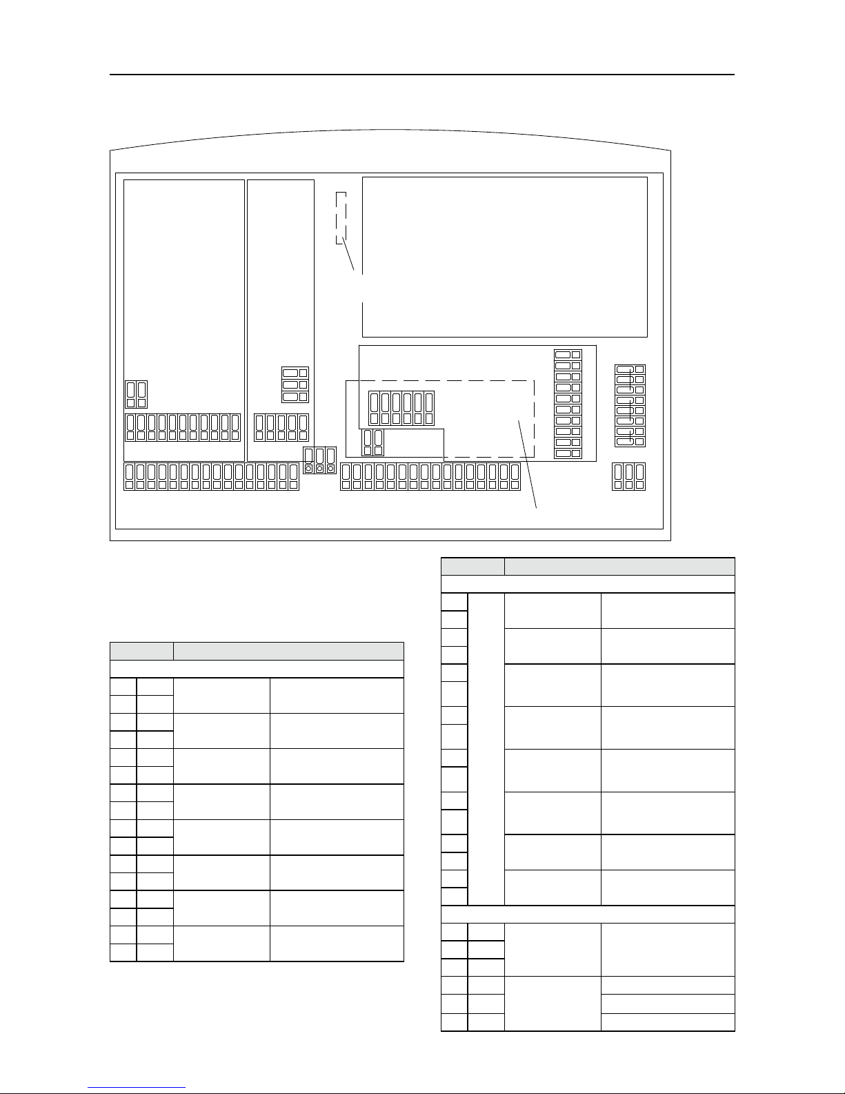
4.4 Technical components
Besides the main board, the following can be fitted in addition
(see paragraph 4.5).
• up to two input components
• an output component and
• an interface component
To operate the TOPAX DX at least one entry component has to
be built in.
output block
mainboard
DO4 DO3 DO2 DO1
78404
78403
78402
DO7 DO6 DO5
DO0
78399
PC interface RS 485(hidden)
78406
+-
+-
+-+-+-+-+-+-
1
2
3
4
5
6
7
8
9
10
11
12
13
14
15
16
17
18
19
20
21
22
23
24
25
26
27
28
29
30
31
32
20 mA Power Outputs Digitale Outputs
36
37
38
PE
N
L
power generator
33
34
92
93
94
87
88
89
90
91
86
-+
81
82
83
84
85
- -+ +
56
57
58
59
60
-+
51A
52A
53
54
55
61
51B
52B
- -+ +
-
+
71
72
73
74
75
76
77
78
5-fold input block
Alarm relays
39
40
41
43
44
45
46
42
35
95
96
B
A
3-fold
input block
Plugin connector
to the display circuit board
Fig. 4.5:Adjustment of the technical components on the main board
Mainboard (Order-No. 78402)
The mainboard holds the technical components and has its own
connectors::
• 8 analog powerinputs (0/4-20 mA)
• 8 digital inputs
• Alarm relay
• Power supply
5-fold input board (Order-No. 78403)
with 5 measurement inputs for:
• Free chlorine (amperometric or membrane covered elec-
trode) (0/4-20 mA)
• pH value combination electrode
• Redox combination electrode
171 mm
267 mm 302 mm
240 mm
171 mm
267 mm 302 mm
240 mm

BA-40100-02-V04 | Maintenance Instructions TOPAX DX | 9
Chapter 4: Installation
• Temperature sensor Pt100
• Position feedback of an eventual servo motor with potenti-
ometerr
3-fold input board (Order-No. 78404)
with 3 measurement inputs for:
• Free chlorine potentiostatic electrode
• Position feedback of an eventual servo motor w. potentiometer
• 0/4 20 mA power entrance for the connection of a distur-
bance factor or a conductivity measuring unit with upstream
measuring amplifier
IMPORTANT!
When free chlorine potentiostatic electrode is used
in a 5-fold input block, it is possible to connect also
a total-chlorine electrode. At the same time bonded
chlorine is calculated by PC and displayed.
Output board (Order-No. 78399)
On the output block there are 5 integrated relay output and 3
electronic outputs (optocouplers).
The following output can be configured:
• Controller output free chlorine with different functions
• Controller output pH value with different functions
• Controller output bonded chlorine with different functions
• Controller output conductivity with different functions
• DIN contact – Free contact if all conditions of the DIN-
Standards are respected.
• Contact for starting of the flocking pump.
These outputs are assigned automatically in the software con-
figuration.
1. Automatic controller free chlorine
2. Automatic controller pH value
3. Automatic controller bound chlorine
4. Automatic controller conductivity
5. DIN - contact
6. Eco - contact
Depending upon output type, TOPAX DX selects the next free
relay output or optocoupler. The clamps are assigned in a firm
order: clamps 87/88 to 95/96 for relays, or 81/82 bis 85/86 for
optocouplers.
NOTE!
See also terminal clips in Chapter 4.6
Interface board RS 485 (Order-No. 78406)
The TOPAX DX has the option of being fitted with a serial inter-
face RS 485. The RS 485 allows you to transfer data to a PC.
The MODBUS-Protocol is installed for the protocol of the data
transfer.
With the RS 485 interface it is possible to connect more than one
TOPAX DX to a network. For this purpose each TOPAX DX has
to be allocated an address. In addition to this each TOPAX DX is
fitted with a computer-interface RS 485.
It is possible to have a maximum of 1000 m of data transfer with
the RS 485 interface. Up to 14 TOPAX DXs can be connected to
a network with a PC.
An example of a network with more than one device is shown in
chapter 17.
BEWARE!
The data line is to be attached direct to the connec-
ting terminals of the TOPAX (clip A and B). Separate
clamping or branching boxes should not be set. The
network address 10 is not allowed.
IMPORTANT!
For the realization of a network with the TOPAX DX
and the structure of a bus system to a PC a computer
cable “KAT.5 type 2X2XAWG24/1 (Lapp cable)” or
better is to be used
Use of simple cables can cause data errors and affect the data
communication for which the manufacturer will not be liable!
The screen is to be connected, for electromagnetic compatibility
reasons, before the doing the various connections and these are
to be secured with protective ground. In this measure it must be
guaranteed that over the screen no potential equalization stream
can flow. The connection with GND and the shielding are to be
accomplished in accordance with DIN/VDE 0160 and DIN 57
899/VDE 0800.
Most modern computers are equipped with the serial computer
interface R-S 232 and/or with USB - interfaces. For this reason
the data with an interface converter R-S 485 R-S 232 or R-S 485
USB are to be converted.
The interface board RS 485 is placed in the rear shell of the
TOPAX DX device, between main board and 3-fold output block.
There are interface components in the under casing part of the
main board in the TOPAX DX. They are partially hidden from view
by the output components (see Fig. 4.6).
Fig. 4.6: RS 485 connections on the interface component’s board partially hid-
den from view by the output components.
10 | Maintenance Instructions TOPAX DX | BA-40100-02-V04
Chapter 4: Installation
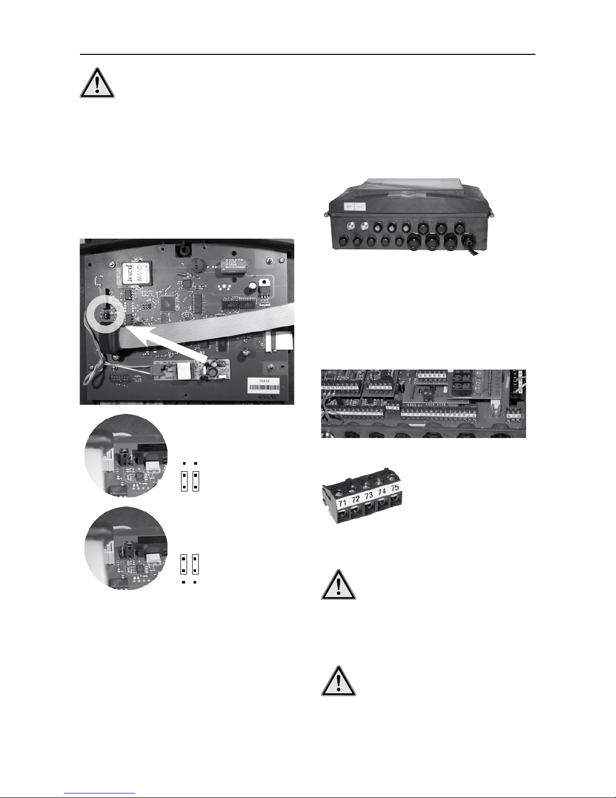
BEWARE!!
The data line must be locked at both sides with a
120 Ohm line resistance and must be supplied a
firm potential using the two link plugs on the two
jumpers on the circuit board of the display of all la-
test TOPAX DX versions.
Two link plugs/jumpers have to be connected to the TOPAX DX
(the last one in the network) for the 120 ohm switch, Pull-up
and Pull-down resistances. The resistances are not active in its
delivered state.
The jumper plug-in slots are located in the upper casing on the
display board, above the flat band-connection to the main board
(see fig. 4.7).
OFF
- delivery status
- resistances are NOT activated
- jumpers are set down
ON
- in the network
- resistances are activated
- jumpers are set up
Fig. 4.7: Position and setting of the jumper to activate the RS 485 resistances
on the last TOPAX DX in the network.
TopView Software
For the remote indication a visualization program is offered in
two versions. One of them, the program TopView mini, is free of
charge and can be downloaded from Internet on.
4.5 Power connections
The equipment may be installed and attached only by authorized
and qualified electricians. The connection has to take place as
per the attached terminal diagrams.
Insert the cables in the various connections screwed on the bot-
tom side of the housing. After the installation, tighten all cable
connections so that the required protection class is provided (see
Fig. 4.8).
Fig. 4.8:Connections screwed, to reach the required protection class.
For the connection to the power supply and to the actuators,
TOPAX DX is equipped with special terminal clips (see Fig. 4.9).
For a better assembly these clamps are designed plug-ins,
whereby the maximum cross section is 2.5 mm2 for the power
cord and 1.5 mm2 for all other cable to the terminal clips (see
Fig. 4.10),.
Fig. 4.9:The principle of the connecting terminal to the technical components.
Fig. 4.10: Individual connecting terminals, removable for installation, of the
technical components.
BEWARE!
When selecting cables and lines as well as when
installation connecting the equipment to other elec-
trical peripheries make sure to comply with the regu-
lations of VDE 0100 for high voltage systems (rated
voltages up to 1000 V) and/or the respective natio-
nal regulations of your country!
BEWARE!
The equipment is not suitable for the installation in
explosive conditions!

BA-40100-02-V04 | Maintenance Instructions TOPAX DX | 11
Chapter 4: Installation
Input and output connections
IMPORTANT!
The attached terminal diagrams are dependent on
the software-configuration of the TOPAX®DX. The
configuration depends on the delivered equipment.
The delivered equipment of the TOPAX DX is listed in the pro-
tocol.
If the current software-configuration is not correct, the TOPAX DX
has to be new configured before connecting (see Chapter 4.8).
New new terminal diagrams will be displayed after the configura-
tion.
Voltage supply
This instrument has no power switch and is immediately opera-
tive after the creation of the operating voltage. For this reason an
external switch and/or protective switch is to be planned.
The connectors for the voltage supply are located on the main
board (see Chapter 4.6).
BEWARE!
DO NOT let power be switched on via timer opera-
tion!
Internal fuse
The TOPAX DX is internally secured with a micro fuse T2A. The
internal safety device is designed to break the voltage supply in
case of short-circuits. An additional outside security of voltage
supply should not fall below a value of 2 A (slow-acting).
The fuse is located in the under casing on the power supply board
(see diagram 4.11 and 4.12). To change the fuse the guard over
the power supply has to be removed with the help of a cross-slot
screwdriver (4 screws).
Fig. 4.11: Position of the power supply unit in the under casing.
Fig. 4.12: Position of the fuse on the power supply board.
Sensor technology
Measuring cables may not be parallel when too close (less than
15cm) to power switches and/or cables for power installation.
Separate cable channels are to be used. Disturbing stray effects
could otherwise falsify the measurement. Power switches and
holding wires may cross in short distance only right-angled. The
maximum permissible length of the measuring cables depends
on the kind of the sensor. When performing very ohmic measure-
ments (e.g. pH or REDOX measurements) the following is to be
considered:
• Connections and patch cords must be clean and dry
• The permissible bending radius of the cable must be
respected.
• The quality of the holding wires must correspond to the
defaults from the data sheet of the sensor.
BEWARE!
If possible a continuous cable is to be used from the
sensor to the measuring entrance. Extension of the
cable by means of plugs and/or clamps increases
the risk of disturbances by contamination, humidity
or high transition resistances.
Actuator
When connecting your actuator the equipment must be switched
off to prevent uncontrolled starting and malfunctioning.
NOTICE!
In order to prevent short-circuiting when welding the
load circuit and the output relays, isolate the circuit
from the maximum relay current.
Replacing the battery
The life of the battery (Typ VARTA, CR1/2 AA, 2 Volt Lithium) pro-
vided with the internal instrument clock is approx 5 – 10 years.
When the batteries wear out causing a power shortage, a warn-
ing message will be displayed on the instrument.
The battery is welded on the display circuit board and must be
replaced by a skilled technician (see Fig. 4.13).
Fig. 4.13: Battery for internal clock, on the display circuit board.
12 | Maintenance Instructions TOPAX DX | BA-40100-02-V04
Chapter 4: Installation
4.6 Terminal clips on the technical components
output block
mainboard
DO4 DO3 DO2 DO1
78404
78403
78402
DO7 DO6 DO5
DO0
78399
PC interface RS 485(hidden)
78406
+-
+-
+-+-+-+-+-+-
1
2
3
4
5
6
7
8
9
10
11
12
13
14
15
16
17
18
19
20
21
22
23
24
25
26
27
28
29
30
31
32
20 mA Power Outputs Digitale Outputs
36
37
38
PE
N
L
power generator
33
34
92
93
94
87
88
89
90
91
86
-+
81
82
83
84
85
- -+ +
56
57
58
59
60
-+
51A
52A
53
54
55
61
51B
52B
- -+ +
-
+
71
72
73
74
75
76
77
78
5-fold input block
Alarm relays
39
40
41
43
44
45
46
42
35
95
96
B
A
3-fold
input block
Plugin connector
to the display circuit board
Fig. 4.14: Rear casing with main board, 5-fold input block „78403“, 3-fold input
block „78404“, output board „78399“ and interface board „78406“.
Main board („78402“)
Terminal clip Function
0/4-20 mA Analogue power outputs (see paragraph 10)
1 + Measurement output
0/4...20 mA
free chlorine
2 -
3 + Measurement output
0/4...20 mA
pH-value
4 -
5 + Measurement output
0/4...20 mA
REDOX
6 -
7 + Measurement output
0/4...20 mA
Temperature or programmed as
controller output
8 -
9 + Measurement output
0/4...20 mA
Bonded Chlorine or programmed
as controller output
10 -
11 + Measurement output
0/4...20 mA
Conductivity or programmed as
controller output
12 -
13 + Continuous controller
output, 0/4...20 mA
programmed as controller output
14 -
15 + Continuous controller
output, 0/4...20 mA
programmed as controller output
16 -
Terminal clip Function
Digital inputs
17 Potential free input Water shortage (normally ON or
normally OFF)
18
19 Potential free input Filter cleaning (normally ON or
normally OFF)
20
21 Potential free input Level pre-alarm Controller 1
(normally ON or normally OFF or
not active)
22
23 Potential free input Level alarm Controller 1
(normally ON or normally OFF or
not active)
24
25 Potential free input Level pre-alarm Controller 2
(normally ON or normally OFF or
not active)
26
27 Potential free input Level alarm Controller 2
(normally ON or normally OFF or
not active)
28
29 Potential free input free
30
31 Potential free input Activate night-time reduced
operation
32
33 A PC interface Inbuilt interface for Software-
Update
34 B
35 GND
36 Alarm relay as bus
alarm
Opener
37 Middle contact
38 Closer

BA-40100-02-V04 | Maintenance Instructions TOPAX DX | 13
Chapter 4: Installation
Terminal clip Function
39 PE Protection conductor Voltage: 90 up to 264VAC
40 PE
41 N Neutral conductor
42 N
43 N
44 L Phase
45 L
46 L
BEWARE!
The 0/4 20 mA continuous automatic controller out-
puts are automatically assigned in the software con-
figuration.The clips are assigned in a firm order.
Ranking of the outputs for automatic allocation:
1. automatic controller output free chlorine
1. automatic controller output pH - value
1. automatic controller output bound chlorine
1. automatic controller output conductivity
Terminal clips sequence for the automatic allocation:
• Terminal clips 15/16
• Terminal clips 13/14
• Terminal clips 11/12
• Terminal clips 9/10
• Terminal clips 7/8
Terminal clips allocation is displayed at the end of programming
(see chapter 10).
5-fold input block („78403 - CPRT(ATE)“)
Terminal clip Function Color Remark
51A + free chlorine
(amperometric elec-
trode Typ CS 120)
Electrode mating
copper/platinum
or silver/platinum
possible
CS120 (Cu/Pt)
Cu : blue (-)
Pt : red (+)
CS120 (Ag/Pt)
Ag : violett (-)
Pt : red (+)
Variant A and
variant B can be
only used as an
alternative.
52A -
51B + Total chlorine measuring electrode
(4-20 mA) - encapsulated free chlorine
electrode (4-20 mA) - 20 mA input
with 24 VDC sensor power
52B -
53 + pH-value
54 -
55 + Redox
56 -
57 Temperature
(Polarity at wish)
58
59 Potentiometer with positional feedback for Servo motor
(Polarity of clips 59 and 61 is at wish)
60 Slider
61
3-fold input block („78404 - C(P)20mA(ATE)”)
Terminal clip Function Color
71 Reference electrode
(with cable)
free chlorine
(potentiostatic
electrode)
Reference electrode
(glass): black
Counter electrode
(stainless steel): red
Measurement electrode
(Gold): violett
72 Counter electrode
(stainless steel)
73 Measurement electrode
(Gold)
74 + 20 mA passively (without supply to the
sensor) - conductivity measurement or
disturbance factor
75 -
76 Potentiometer with positional feedback for
servo motor
(Polarity of clips 76 and 78 is at wish)
77 Slider
78
Output block („78399“)
Termi-
nal clip
Output
81 + Elektronic output
(DO7) (Optocoupler)
programmable
82 -
83 + Elektronic output
(DO6) (Optocoupler)
programmable
84 -
85 + Elektronic output
(DO5) (Optocoupler)
programmable
86 -
87 Relay output (DO 4) programmable
88
89 Relay output (DO 3) programmable
90
91 Relay output (DO 2) programmable
92
93 Relay output (DO 1) programmable
94
95 Relay output (DO 0) programmable
96
BEWARE!
The constant regulating outputs 0/4-20 mA of the
main board are also allocated automatically in the
software configuration as per a fixed rank order of
the terminals, in accordance with the allocation pro-
cedure for the output components.
The following output can be configured:
1. Controller output free chlorine with different functions
2. Controller output pH value with different functions
3. Controller output bonded chlorine with different functions
4. Controller output conductivity with different functions
5. IN contact – Free contact if all conditions of the DIN-Stand-
ards are respected.
6. Contact for starting of the flocking pump.
Depending upon output type, TOPAX DX selects the next free
relay output or optocoupler. The clamps are assigned in a firm
order: clamps 87/88 to 95/96 for relays, or 81/82 bis 85/86 for
optocouplers.
14 | Maintenance Instructions TOPAX DX | BA-40100-02-V04
Chapter 4: Installation
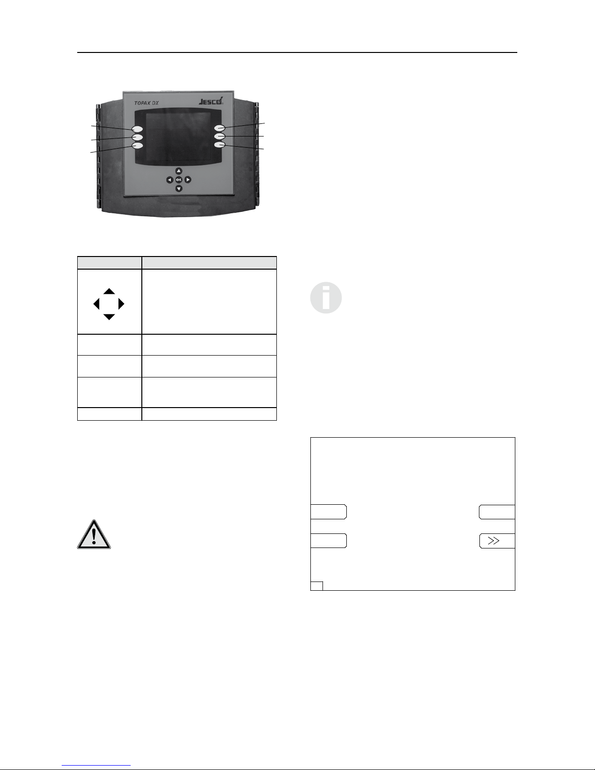
4.7 Operation and keyboard layout
①
②
③
④
⑤
⑥
Fig. 4.15: TOPAX®DX device with control panel. The keys are integrated in a
glass keyboard and react to contact.
Keys Function
Crossed arrow keys
• Menu change-over in the menu „service“;
• Change-over between the individual numbers
• Numerical values change, parameter adjust
Switching between the individual menu options
takes place in each case on depressing the key.
Entering and changing numerical values take
place continuously
„OK“ between the
arrow keys
Input information are received and saved. Suc-
cessful saving is notified by a longer beep
Function key ①:
„ESC“
Leave the menu or one level back without saving
Function key ①:
„ESC“
(hold 5 secondsn)
Return to the main menu
Buttons ②- ⑥Functions are indicated in the display
If no operation takes place, the automatic controller turns back
into the measuring mode after approx. 5 minutes. Changed pa-
rameters, which were not confirmed with the “OK” key, are not
stored.
Exception: During the calibration and with the configuration no
“time out” takes place!
NOTE!
If no values are to be changed, “ESC” can be pressed
and the selected menus left at any time. Changed
values are confirmed with the “OK” button. If the
changed values are not saved with the “OK” button,
the device functioning goes on with default settings.
Exception: Clock and timer settings.
Basically:
• The values can be changed only within the permissible
range of values.
• The function of the key is signalled with a tone.
• Some functions can be protected by a password against
unauthorized access (see Chapter 16, Menu 5.9 „pass-
word“).
4.8 Initial operation and configuration
Switch on the power.
TOPAX DX is programmed by the manufacturer based on custom-
ers’ specs before shipment and is supplied along with a terminal
connection diagram. Ineffective or impossible configurations (for
instance double assignment of the outputs) are not admissible.
Failure of the customer to supply instructions on his purchase
order, TOPAX DX shall be programmed by the manufacturer to
the standard default settings (see Chapter 19).
For the initial start-up the operator has to configure the TOPAX
DX and set its sensors and the installed actuating elements as
well as set special functions. The relevant in- and outputs of the
TOPAX DX are automatically chosen based on this information
and the relevant connecting terminals are shown.
After a successful configuration the TOPAX DX starts up with a
standard display (see chapter 16). A subsequent renewed con-
figuration can be carried out via the Service-Menu (see chapter
16, menu 5 “Configuration”).
IMPORTANT!
For a better overview, all menus are shown on the
display with an ID-number marked on the bottom line
on the left.(see Fig. 4.16).
Choice of Language
After a short hardware test the TOPAX DX during the initial start-
up, the TOPAX DX displays the Home page for Configuration
(see diagram 4.16). This screen is shown until a language has
been chosen by pressing the key ②(German), ③(English), ⑤
(French) or ⑥(further languages “>>”) – see diagram 4.15 and
4.16.
Lutz-Jesco GmbH
Am Bostelberge 19
30900 Wedemark
Deutsch
English
Francais
0.1 Software Version: ...........
TOPAX DX Start
Fig. 4.16: Home page for the configuration of language choice.
Further languages – MMC Memory card
Besides the fixed installed languages of German and English
there is other language data for the TOPAX DX. This can be writ-
ten on an external data storage unit, a MMC Memory card, and
then imported by the TOPAX DX. For further questions regarding
the availability of languages please ask the manufacturer.

BA-40100-02-V04 | Maintenance Instructions TOPAX DX | 15
Chapter 4: Installation
The MMC (Multi-Media-Card) Memory card with the language
data is inserted on the display board in the upper casing (see
Fig. 4.17).
IMPORTANT!
When inserting the MMC Memory card the device
has to be turned off.
Fig. 4.17: Slot for the MMC Memory card on the display board. The memory
card transfers further language data, from Firmware-Updates and
from the logbook’s data.
The additional languages are available in the Configuration under
⑥(further languages “>>”).
Press the ⑥key and chose the desired language with the ar-
row keys ▲and ▼. Confirm with the “OK” key. The language is
loaded into TOPAX DX.
Lutz-Jesco GmbH
Am Bostelberge 19
30900 Wedemark
Tel: 05130/58 02-0
Fax: 05130/5802-68
http://www.jesco.de/
For help please press the “Help” button
help next
0.2
TOPAX DX configuration
Fig. 4.18 / Menu 0.2: Confirmation of chosen language.
After having chosen the language the TOPAX DX moves to the
menu 0.2 (see fig. 4.18). Now you can start directly with the
configuration, select key ③(“next”), and/or the Help-Menu, key
⑥ (“help”).
Help-Menu
The Help Menu is available as a point of help for many menu
points. By pressing a random key the TOPAX DX returns to the
previous menu again.
Menu 0.4: Configuration of the terminals for sensors and
actuating elements.
After choosing a language the TOPAX DX goes to menu 0.2. By
pressing the “next” key, the TOPAX DX goes to menu 0.4.1.
The TOPAX DX checks by means of the installed components,
which connections are possible and offers per the connections
presents a choice in options.
Menu 0.4.1: Input free chlorine
With the arrow keys ▲und ▼you can select between the fol-
lowing options:
• CS120 cell (direct)
• potentiostat
• membran covered cell
• Redox-Sensor
The selected option is highlighted in grey. The entry is confirmed
with the “next” key or ▶. The TOPAX DX then goes to the next
menu.
IMPORTANT!
The configuration does not run automatically through
all the menus shown here. It depends on the confi-
guration of the TOPAX DX on delivery.
Menu 0.4.2: Output free chlorine
With the arrow keys ▲und ▼you can select between the fol-
lowing options:
• 3 point step with poti
• 3 point step without poti
• impulsefrequency (opto)
• impulsefrequency (relais)
• impulslength (relais)
• current output relais (20 mA)
• ON/OFF (relais)
• no output
The selected option is highlighted in grey. The entry is confirmed
with the “next” key or ▶. The TOPAX DX then goes to the next
menu. Press„back“ or ◀to go to the previous menu.
Menu 0.4.3: output pH value
With the arrow keys ▲und ▼you can select between the fol-
lowing options:
• 3 point step with poti
• 3 point step without poti
• impulsefrequency (opto)
• impulsefrequency (relais)
• impulslength (relais)
• current output (20 mA)
• 2 sides imp.freq.(opto)
• 2 sides imp.freq.(relais)
• 2 sides imp.length.(relais)
• ON/OFF (relais)
• no output
The selected option is highlighted in grey. The entry is confirmed
with the “next” key or ▶. The TOPAX DX then goes to the next
menu. Press„back“ or ◀to go to the previous menu.

16 | Maintenance Instructions TOPAX DX | BA-40100-02-V04
Chapter 4: Installation
Menu 0.4.4: input Redox
With the arrow keys ▲und ▼you can select between the fol-
lowing options:
• ON
• OFF
The selected option is highlighted in grey. The entry is confirmed
with the “next” key or ▶. The TOPAX DX then goes to the next
menu. Press„back“ or ◀to go to the previous menu.
Menu 0.4.5: input temperature
With the arrow keys ▲und ▼you can select between the fol-
lowing options:
• ON
• OFF
The selected option is highlighted in grey. The entry is confirmed
with the “next” key or ▶. The TOPAX DX then goes to the next
menu. Press„back“ or ◀to go to the previous menu.
Menu 0.4.6: intput total chlorine
With the arrow keys ▲und ▼you can select between the fol-
lowing options:
• ON
• OFF
The selected option is highlighted in grey. The entry is confirmed
with the “next” key or ▶. The TOPAX DX then goes to the next
menu. Press„back“ or ◀to go to the previous menu.
Menu 0.4.7: output combined chlorine
(Menu appears, when input total chlorine is ON.) With the arrow
keys ▲und ▼you can select between the following options:
• impulsefrequency (opto)
• impulsefrequency (relais)
• impulslength (relais)
• current output (20 mA)
• ON/OFF (relais)
• no output
The selected option is highlighted in grey. The entry is confirmed
with the “next” key or ▶. The TOPAX DX then goes to the next
menu. Press„back“ or ◀to go to the previous menu.
Menu 0.4.8: input conductivity
With the arrow keys ▲und ▼you can select between the fol-
lowing options:
• ON
• OFF
The selected option is highlighted in grey. The entry is confirmed
with the “next” key or ▶. The TOPAX DX then goes to the next
menu. Press„back“ or ◀to go to the previous menu.
Menu 0.4.9: output conductivity
(Menu appears, when input conductivity is ON.) With the arrow
keys ▲und ▼you can select between the following options:
• impulsefrequency (opto)
• impulsefrequency (relais)
• impulslength (relais)
• current output (20 mA)
• ON/OFF (relais)
• no output
The selected option is highlighted in grey. The entry is confirmed
with the “next” key or ▶. The TOPAX DX then goes to the next
menu. Press„back“ or ◀to go to the previous menu.
Menu 0.4.10: output floculation pump
With the arrow keys ▲und ▼you can select between the fol-
lowing options:
• impulsefrequency (opto)
• impulsefrequency (relais)
• impulslength (relais)
• current output (20 mA)
• ON/OFF (relais)
• OFF
The selected option is highlighted in grey. The entry is confirmed
with the “next” key or ▶. The TOPAX DX then goes to the next
menu. Press„back“ or ◀to go to the previous menu.
Menu 0.4.11: output DIN-contact
With the arrow keys ▲und ▼you can select between the fol-
lowing options:
• relaiscontact
• optocupler
• eco-control
• OFF
The selected option is highlighted in grey. The entry is confirmed
with the “next” key or ▶. The TOPAX DX then goes to the next
menu. Press„back“ or ◀to go to the previous menu.
Menu 0.4.12: output eco control
(Menu appears, when output DIN-contact is set to eco-control.)
With the arrow keys ▲und ▼you can select between the fol-
lowing options:
• optocupler
• relaiscontact
The selected option is highlighted in grey. The entry is confirmed
with the “next” key or ▶. The TOPAX DX then goes to the next
menu. Press„back“ or ◀to go to the previous menu.
Menu 0.4.13: output flow input
(Menu appears, when input conductivity is OFF.) With the arrow
keys ▲und ▼you can select between the following options:
• 0-20mA
• 4-20 mA
• OFF
The selected option is highlighted in grey. The entry is confirmed
with the “next” key or ▶. The TOPAX DX then goes to the next
menu. Press„back“ or ◀to go to the previous menu.

BA-40100-02-V04 | Maintenance Instructions TOPAX DX | 17
Chapter 4: Installation
Menu 0.5: Completing the configuration
The TOPAX DX moves immediately on to the configuration, at the
latest after menu 0.4.11, in the finalising menu (menu 0.5) and
shows the chosen configuration with all the previously chosen
Options in the total overview.
The configuration is saved with the “save” key and the finalis-
ing confirmation key “OK” and the TOPAX DX moves to the next
menu 0.6.1.
The configuration starts from the beginning again with the key
“back”. The TOPAX DX goes back to menu 0.4.1.
news configuration
free chlorine
potentiostat
3 point step with poti
ph value
Impulsefrequency (relais)
combined chlorine
flocculation
impulsefrequency (opto)
DIN-contact
OFF
save
impulselength (relais)
back
conductivity sensor
impulselength (relais)
0.5
REDOX temperature
on on
eco control
off
flow input
off
Menu 0.5: Total overview over all selected options.
Menu 0.6: Terminal connections
According to the chosen Options the TOPAX DX determines the
relevant terminal connections and shows this in menus 0.6.1 to
0.6.4 (each by number of connections).
free chlorine
input clamps analog
next
check clamps and setup
pH value
REDOX
temperature
new configuration
total chlorine sensor
71 - 72 - 73
53 - 54
55 - 56
57 - 58
51B - 52B
0.6.1
connect only with
main voltage off
Menu 0.6.1: Example of a new configuration and the relevant terminal connec-
tion plan.
NOTE!
Make a note of the given connections on the pre-
print in chapter 24.
In order to move between the individual menus 0.6.1 to 0.6.4,
press either the “next” or the “back” key, or the arrow keys ▲
and ▼.
To finalise the total configuration confirm the connection plan
with the “OK” key. The TOPAX DX then moves to the standard
display (see fig. 4.19).
You can find further information on the structure of the Menus for
the TOPAX DX in chapter 16.
mg/l
mV
ºC
comb. cl.
temp.
REDOX
free chlorine pH value
7.040.39
719
mg/l
0.09
26.3
eff. cl. 0.30 mg/l
Topax DX
14:28 06.02.2007
Fig. 4.19: Standard display with the most important measuring values.
NOTE!
After confirming the pre-settings, TOPAX DX starts
up. At start-up the controller outputs of your TOPAX
DX will be function-less for approx 60 seconds. This
time is needed for the stabilization of the electro-
chemical sensors. During this time the status display
shows the message „starting in..... s“ (countdown
seconds are progressively shown). At the end of this
time TOPAX DX is fully operative. All data shown on
the various menus are displayed in clear text.
NOTE!
It is possible to protect your setting against unaut-
horized change by use of a personal password (see
Chapter 16, Menu 5.9).
4.9 Next steps of configuration
After a successful configuration the next steps should be:
• Mount the device
• Attach the sensors and actuating element (to the controlling
pumps and switch, etc.)
• Calibrate the sensors to the measuring output (see chapter
5 and 6)
• Set up the target value of the measuring input (see chapter
16, menu 1.1)
• Set up the control (see chapter 16, menu 2.1)
• Configuration of the regulating output (see chapter 7)
NOTE!
You can repeat the software-configuration during the
normal operation (see chapter 6, menu 5, „configu-
ration“). Here the changes to the terminal plan are
written in red figures.

18 | Maintenance Instructions TOPAX DX | BA-40100-02-V04
Chapter 5: Measuring values inputs
5. Measuring values inputs
This chapter exemplifies the chemical and physical correlation,
which is necessary to understand the behaviour of the input
measuring values.
Measuring values inputs of:
• free chlorine
• pH value
• Redox
• temperature
• total chlorine and display of combined chlorine
• conductivity
The input measuring values are examined for:
WARNING!
When set up the unit for the first time, care should
be taken to perform individual calibration of each
output immediately after connecting the sensors in
the system. TOPAX DX is designed to perform mo-
nitoring of all calibration processes based on reaso-
nable parameters (zero point and conductance) and
the measurements are accurately documented. Non
calibrated value inputs are marked out in clear text.
„Roughly calibrated” values are shown on the main
display in red.
The limits of „Roughly calibrated” are:
Measured value Limit
Slew rate of pH value <53 mV or
> 61 mV
Zero point pH value < -40mV or
> 40mV
Slew rate of Redox < 0,85 mV/mV or
> 1,2 mV/mV
Slew rate of chlorine with
amperometric or potentiostatiic
electrode
< 10µA/mg/l or
> 100µA/mg/l
Slew rate of chlorine with
membrane covered electrode (0..2,00
mg/l)
< 3mA/mg/l or
> 13mA/mg/l
Slew rate of chlorine with
membrane covered electrode
(0..5,00/10,00 mg/l)
< 1mA/mg/l or
> 5,2mg/l
The remark „Roughly calibrated” sheds light on the calibration
quality and the conditions of the electrochemical electrodes.
5.1 „Free chlorine“ values input
The value of „free chlorine“ is dependent on the Ph-value of the
streaming water flow which results form the reaction of chloride
ions to different Ph values. This relationship further determines
the chlorine dissociation curve based on Ph-value (see fig. 5.1).
free chlorine
Hyperchlorous acid
Fig. 5.1: Chlorine dissociation curve.
For photometric measurements the Ph-value of the sample is
soaked in a Ph-buffer of approx 6,5 in order to obtain a meas-
urement of a higher content of effective chlorine than actually
available in the water stream. In the presence of high Ph-val-
ues significant differences will occur between expected and ac-
tual disinfection if assessed by photometric analysis. The main
display will show therefore 2 free chlorine values: (a) results of
photometric analysis and (b) the content of effective chlorine to
assure the germicide effect at the Ph-value of the process me-
dium.
Technical characteristics
Power signal is received from excess chlorine detector using
2 electrodes, a potentiostat or a membrane-enclosed sensor
(measuring signal 4 – 20mA).
Applicable measuring ranges:
Type of detectors Measuring range
Excess chlorine detector with 2 electrodes
CS1202
Type: CS120
0 ... 1.00 mg/l
0 ... 2.00 mg/l
0 ... 5.00 mg/l
0 ... 10.00 mg/l
Potentiostat
Type: PM
0 ... 1.00 mg/l or
0 ... 2.00 mg/l
Membrane-enclosed sensor
Type: Cl 4.1 A 2
Type 20 mA
Set measuring range based on
type of detector
Accuracy ± 1 % after calibration
Calibration of amperometric electrode, chlorine sensing-
detector with 2 electrodes (CS120)
Please first select the measuring range of the input (see chapter
16, menu 5.1 “inputs”) and then perform inlet calibration (see
chapter 16, menu 1.2 “calibration”).
In order to calibrate the „Excess chlorine detector with 2 elec-
trodes“, 2-point calibration is required. The physical value (µA)

BA-40100-02-V04 | Maintenance Instructions TOPAX DX | 19
Chapter 5: Measuring values inputs
measured by the detector during calibration is shown on the
display.
Reference value 1: zero point calibration
To perform zero-point calibration, operate the detector in chlo-
rine-free water or just stop the water flow through the instru-
ment. The value of the physical quantity shown on the display
(approx 5-10 µA) can be saved as soon as it stops changing.
To save, simply press „OK“ and wait for the system to switch
automatically over to the next menu selection step.
Reference value 2: DPD
Operate the detector in the flow-through water. The instrument
starts measuring the content of chlorine in water, as soon as the
physical quantity shown on the display becomes stable and stops
changing. In order to avoid signal variations and consequent
reading errors, water must be taken at the sensing element and
the actual signal must be saved directly in the TOPAX DX upon
taking of the water sample. The content of chlorine in water is
measured by means of the DPD method. The measurement must
be set in the controller and saved by pressing OK.
Once the measurement is saved, the resistivity of the excess
chlorine detector is displayed. The typical resistivity value is
approx. 25–35 µA (depending on water type) per mg/l of free
chlorine. The accuracy of resistivity measurements is monitored
throughout the process.
1-point calibration is sufficient (reference value 2) for validation
of the chlorine content after optimization.
Calibration of potentiostatic electrode, chlorine sensing-
detector with potentiostat (PM)
Please first select the measuring range of the input (see chapter
16, menu 5.1 “inputs”) and then perform inlet calibration (see
chapter 16, menu 1.2 “calibration”).
Reference value: DPD
Operate the detector in the flow-through water. A nearly stable
physical value should be displayed. In order to avoid signal vari-
ations and consequent reading errors, water must be taken at
the sensing element and the actual signal must be saved directly
in the TOPAX DX upon taking of the water sample. The content
of chlorine in water is measured by means of the DPD method.
The measurement must be set in the controller and saved by
pressing OK.
Once the measurement is saved, the resistivity value of the ex-
cess chlorine detector is displayed. The typical resistivity is ap-
prox. 35 µA (depending on water type) per mg/l of free chlorine.
The accuracy of resistivity measurements is monitored through-
out the process.
After calibration of the free-chlorine is completed, you may even-
tually switch to calibration of the “total chlorine detector” by sim-
ply pressing on „next”.
NOTE!
When measuring the free chlorine with a potentio-
stat it is possible to perform a compensation of the
pH-value and temperature by simply connecting a
pH-electrode and a temperature sensor to TOPAX DX
(see chapter 16, menu 1.2 „calibration“)
Membrane-encapsulated sensor
Please first select the measuring range of the input (see chapter
16, menu 5.1 “inputs”) and then perform inlet calibration (see
chapter 16, menu 1.2 “calibration”).
WARNING!
When measuring free chlorine by means of a fully
encapsulated electrode, make sure to connect both
terminal clips 51 B and 52 B. These clips are respec-
tively used to feed the 20 mA signal of the electrode
into the controller and to supply 24 VDC operating
power to the sensing electronics of the electrode.
Zero point calibration
Zero point calibration of the sensing electrode is normally not a
must-requirement, as tuning of the 4 – 20 mA output signal of
the electrode is done on input 4 – 20 mA (4 mA corresponds to
0,00 mg/l free chlorine).
However, a zero-point calibration may be still required due to
the tolerances of the sensing electronics of the electrode. For
this reason the zero-point must be set upon first setup of the
instrument.
Reference value: DPD
Operate the detector in the flow-through water. A nearly stable
physical value should be displayed. In order to avoid signal vari-
ations and consequent reading errors, water must be taken at
the sensing element (electrode) and the actual signal must be
saved directly in the TOPAX DX upon taking of the water sample.
The content of chlorine in water is measured by means of the
DPD method. The measurement must be set in the controller and
saved by pressing OK.
Once the measurement is saved, the resistivity of the excess
chlorine detector is displayed. The accuracy of resistivity meas-
urements is monitored throughout the process.
BEWARE!
The signal from the excess-chlorine sensing detec-
tor is converted by the electrode into an impressed
current pulse of 4-20 mA. Whenever your TOPAX DX
features a lower value than 3.5 mA, an alert mes-
sage is displayed [„Eingang 1 Sensorfehler“ = Input
1 sensor failure], the alarm relay is switched on and
the measurement input 1 is marked out in RED.
5.2. „Ph“ values input
Technical characteristics
Input Voltage signal from a pH-electrode
Input resistance 109 Ohm
Accuracy 1 % (after calibration)
The pH-electrode supplies a voltage that is proportional to the
Ph-value.
This voltage is defined by the Nernst voltage (Ettinghausen-
Nernst-Effect), which is the amount of voltage variation per unit

20 | Maintenance Instructions TOPAX DX | BA-40100-02-V04
Chapter 5: Measuring values inputs
Ph which depends on the temperature of the measuring medium.
(see scientific publications or DIN 19261).
The correlation of Nernst voltage and temperature results into
the following table:
t (°C) U (mV) t (°C) U (mV) t (°C) U (mV)
0 54,20 35 61.14 70 68,08
5 55,19 40 62,13 75 69,08
10 56,18 45 63,12 80 70,07
15 57,17 50 64,12 85 71,06
20 58,16 55 65,11 90 72,05
25 59,16 60 66,10 95 73,04
30 60,15 65 67,09 100 74,04
The Nernst voltage is measured by a pH-glass electrode and a
control-electrode integrated into a Ph-sensing electrode.
Calibration
Calibration of the electrode may be performed by ways of „2-
point calibration“ with 2 buffer solutions or by „1-point calibra-
tion” with final input of the resistivity value. The mandatory condi-
tions for using „1-point calibration“, is that the resistivity of the
sensing electrode must be priory measured in a lab.
The actual voltage of the electrode and the design value of buffer
solution are displayed on the TOPAX DX during calibration so that
the electrode can be actually graded while performing the cali-
bration process.
The reaction time for any brand new electrode is just a few sec-
onds and the electrode is considered as fully adjusted when the
physical reading becomes stable. Used second-hand electrodes
may have a longer reaction time.
Connect the electrode to your TOPAX DX by means of a BNC plug
connector or directly to input terminal clips.
2-point calibration
Calibration of the Ph-sensing electrode is performed by select-
ing the menu item “2-points calibration” (see chapter 16, menu
1.2).
The physical measuring value (mV) on the electrode is displayed
in the menu along with the design measuring value that should
be ideally assessed for the Ph.
Buffer-solution 1: zero-point calibration
Soak the pH-electrode in a buffer solution corresponding ap-
proximately to the zero point of the electrode. The ideal electrode
zero-point (0 mV) is at a pH of 7.00. However, the real zero-point
shows minimum variations as against this minimum value. For
zero-point calibration a Lutz-Jesco buffer solution of pH 6.80 is
available. When soaking the Ph-electrode in this solution, a volt-
age of 12 mV should be displayed on the TOPAX DX. Keep in
mind that the physically measured value may slightly differ from
the design value.
When the physical value on the display becomes stable, you may
save the calibrated value by pressing „OK“.
BEWARE!!
Should the actual measured voltage strongly differ
from the design zero-point of the electrode, it means
there is a zero-point drift of the electrode. Zero-point
drift should not exceed the specifications of the DIN
Standards 19265. In the event of zero-point drift ex-
ceeding …… nV, TOPAX DX warns you about possi-
ble bad prove calibration.
Buffer-solution 2: resistivity calibration
Accurately clean the electrode with deionised or distilled water
before calibration of the resistivity.
WARNING!
Avoid rubbing off glass electrodes as you may provo-
ke accumulation of static electricity in the electrode
which in turn would result into faulty readings!!
To perform calibration of resistivity you need a buffer solution that
differs from the zero-point by at least 2 Ph-points. Lutz-Jesco
buffer solutions with a Ph of 9.27 are available for this purpose.
Should you use a different buffer solution for calibration of the
resistivity, you first need to set TOPAX DX to the Ph of your other
solution. When soaking the Ph-electrode in this buffer solution
(Ph = 9.27), a voltage of -134 mV should be displayed on the
TOPAX DX. Keep in mind that the physically measured value may
slightly differ from the design value.
When the physical value on the display becomes stable, you may
save the calibrated value by pressing „OK“ and wait for the resis-
tivity of the electrode to be displayed.
In accordance with the DIN Standards 19265 the resistivity if an
electrode should range between 52 and 59 mV per pH-value.
Zero-point stability and accuracy of the measured resistivity are
consistently monitored.
BEWARE!
Resistivity values may not strongly differ from the va-
lues mentioned herein. If not, check the combination
electrode or the power supply cable and its quick
connector. Should zero-point and resistivity values
of the combination electrode exceed the admissible
tolerances, the system notifies the operator with a
warning message. In this case provide for immediate
replacement of the electrode.
Buffer solution Voltage
3,06 229,15 mV
4,65 136,68 mV
6,80 11,63 mV
9,27 -132,02 mV
WARNING!
Store buffer solutions in a cool and dark place!
Other manuals for TOPAX DX
2
Table of contents


