Jesmay Electronics 2036T/R User manual

JESMAY ELECTRONICS CO., LTD
ROOM 1004, STANHOPE HOUSE
738 KING’S ROAD,
QUARRY BAY, HONG KONG
TEL: (852)2563 4292, 2562 6212
FAX: (852)2565 7026, 2516 9417
E-mail:i[email protected]
Web Site:http://www.jesmay.com.hk
JESMAY
MODEL: 2036T/R
2.4GHz Wireless Multiway Monitor with DVR
Transmit-Receive System
OWNER’S MANUAL
(PLEASE READ BEFORE USE)
JESMAY ELECTRONICS CO., LTD

CHAPTER TABLE OF CONTENTS PAGE
1. Read this first--------------------------------------------------- 2
2. Technical specifications------------------------------------ 3-4
3. Wireless Multiway Monitor with DVR Feature-------- 5
4. System connect sketch map------------------------------ 5
5. Packaging and Accessories------------------------------- 6-7
6. Control Elements---------------------------------------------- 7-11
7. Installation of the system----------------------------------- 11-14
¦ Wireless Multiway Receiver with DVR installation
1) Install hard disk
2) Connect Camera and monitor
3) Connect power cord
4) Connect 2.4GHz Antenna
¦ Camera installation
8. Operating Instruction--------------------------------------- 14-24
¦ Wireless Multiway Receiver with DVR operating
1) DVR system boot
2) DVR set up
3) DVR record
4) DVR playback
¦ Camera operating
9.Trouble –shooting------------------------------------------------ 24
1
1. READ THIS FIRST!
1-1 Safety precautions
1) To reduce risk of electric shock, do not disassemble this device.
2) Use only the supplied power supplies.
3) Defective parts must be replaced by original spare parts only.
4) If you spill liquid on it, unplug the device from the AC outlet to prevent
possible fire or shock hazard and consult authorized service personnel.
5) When cleaning the device, turn it off first, use a clean soft cloth moistened
with a little bit of water to clean it.
6) Do not apply pressure to it or drop it.
7) If does not work correctly, return it to the dealer where it was purchased.
Do not dismantle it by yourself.
8) Do not use the device close to heater, refrigerator or stove.
9) When device is in use, do not direct the lens toward any bright light.
Power line operated equipment or accessories connected to the
device should bear the CE certification mark and should not be
modified in any way that might defeat the safety features, the device
meets all European standards for EMC, safety and radio Frequency,
however interference form other RF Transmitters may occur .the
range of the device is at least 100meters in an open air situation,
however indoor the range is highly influenced by construction
materials applied within the house.
2
NO guarantee or liability will be accepted for any damage caused
due to incorrect use of the device supplied, other than indicated
in this owner’s manual.

2. Technical specifications
ITEM DESCRIPTION
Receiver Frequency 2.4GHz~2.483GHz(4 channels)
Receiver sensitivity -80dBm
Channel design PLL frequency synthesizes
Modulation FM
Antenna Omni-directional
Image sensor 1/4?Color CCD
Picture element 512*582 (PAL), 512*492 (NTSC)
IR on illuminance 10LUX
Transmit Frequency 2.4GHz~2.483GHz(4 channels)
Output power (max) 10dBm(CE), 0dBm(FCC)
Operational range 15-Up to 100 meters (open air situation)
Video Format NTSC / PAL
Operation System AV/RF
Camera Input Channel 4 channel Composite BNC
Monitor Output Channel 2 channel Composite BNC
NTSC 120 fps (4x30 fps)
Display Frame Rate
PAL 100 fps (4 x 25 fps)
Recording Frame Rate NTSC Max 30 fps (Quad)
(Quad) PAL Max.25 fps (Quad)
3
ITEM DESCRIPTION
NTSC Each Channel =30/Number of Source Max. 30 fps
(Each Channel)
Recording Frame Rate
(Each Mode)
PAL Each Channel =25 fps/Number of Source. Max. 25
fps (Each Channel)
Record Mode Continuous, Schedule, Sensor Triggered
Display NTSC: 720 x 480; PAL: 720 x 576
NTSC: 320 x 112, 640 x 224
Quad: 640 x 224 (total)
Resolution
Record
PAL: 320 x 136, 640 x 272 Each:640 x 224
Modified MJPEG (12-20K bytes/frame)
Video Compression Format
(Each Channel) Low :12KB; Normal :15KB; High : 20KB
HDD Support Over 200G Byte, ATA -100 Interface
120G Hard disk @ 7 fame per second @ Normal
Quality
Estimated Record Length
(120*1024*1024 KB) / ( 7*15*60*60 ) = 332h
Method Time, Date, Event
Search
Full Screen YES
Sensor, Alarm 4 Input (Open/Close),1 Input (Relay 2A 28VDC/2A
125VAC)
12VDC/2A, 5V/2.5A (DVR Receiver)
Power supply
12VDC/500mA (Transmitter)
Length 315 * Width 224 * High 52 (Receiver)
Dimension (mm)
Length 155 * Width 70 * High 60 (Transmitter)
4

3 Wireless Multiway Monitor with DVR Feature
Video 4 Channel BNC Camera Input & RF 4 Channel Receive
2 Channel BNC Monitor Output
NTSC / PAL
4 Sets NO/NC Sensor Input
1 Alarm Output (2A 28VDC / 0.5A 125 VAC)
One ATA-100 Hard Disk Interface, Support Over 200G Byte
Time Schedule record, Sensor Triggered Record
IR Remote Control (Optional)
Select Video & RF Received Program via AV/RF operating
1/4?Color CCD
Up to 100 meters operational range
Auto on & off IR led with CDs
4 System Connect sketch map
5
5 Packaging and Accessories
¦Multiway Receiver with DVR
DVR X1
Power Adapter X1 User’s Manual X1 Remote Controller X1
2.4GHz ANT X1 BNC to RCA Connector X1 BNC to BNC wire X1
6
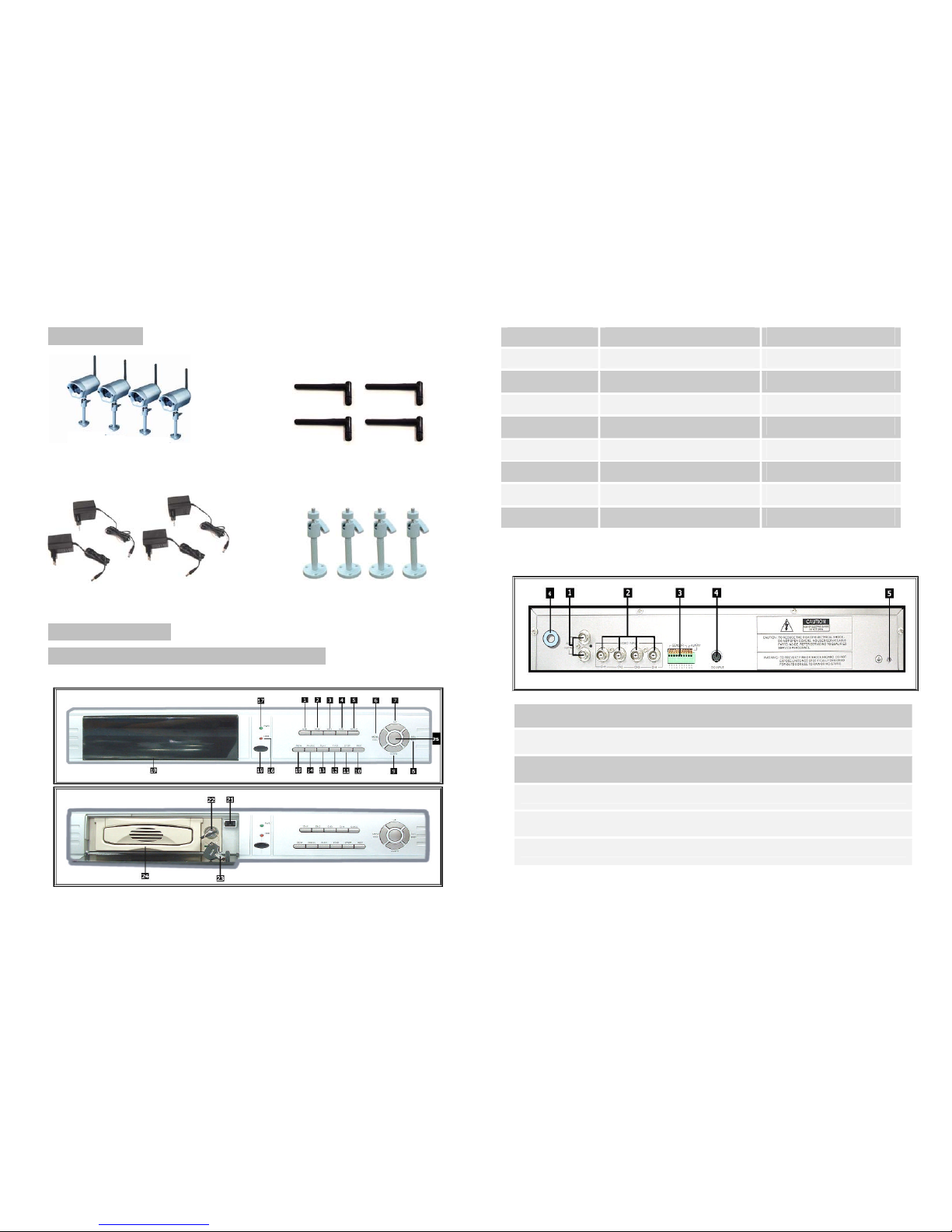
¦Transmitter
2.4GHz Camera X4 2.4GHz ANT X4
Power Adapter X4 Mounting Bracket X4
6 Control Elements
Multiway Receiver with DVR control elements
1)Front panel
7
1 Channel 1 9 Move Down 17 Power Indicator
2 Channel 2 10 Record 18 IR Window
3 Channel 3 11 Stop 19 Swap HDD
4 Channel 4 12 Forward 20 Radiator
5 Quad View 13 Play 21 Press-button
6 Menu /Exit 14 Pause 22 Key Locker
7 Move up 15 Reward 23 Key
8 Select /Edit 16 HDD Access Indicator 24 Active-handle
25 AV/RF
2) Rear Panel:
1. Video Output
2. Video Input
3. Sensor Input/Alarm Output
4. DC POWER
5. Grounding
6. 2.4GHz ANT Input
8

3) Remote Controller
4) Removable HDD Box Introduction
1. Power Indicator 5. Active-handle
2. HDD Access Indicator 6. Radiator
3. Key Locker 7. HDD date cable
4. PVC Frame 8. HDD power cable
9
¦Camera control elements
Rear View of Camera
Front View of Camera
1. Rainproof solid aluminum housing
2. 1/4"CCD Color image sensor
3. IR led with CDs control
4. Aluminum body
5. 2.4GHz Antenna
6. Camera Mounting Bracket
7. 12VDC power connector
8. Channel selection SW(switch) (See Fig4)
? Select the channel by sliding the slide switch to the channel number
you want
? Note1: Open the rubber cover to slide channel selection SW, then replace and
tighten the cover
?Note2: You must be set different channel each Camera
10
1. CH1 2.CH2
3.QUAD 4.CH3
5.CH4 6.AV/RF
7.STOP 8.RECORD
9.PAUSE 10.REWARD
11.FORWARD 12.PLAY
13.UP 14.MENU
15.DOWN 16.ENTER
17.PROG-CH1 18.PROG-CH2
19.PROG: AV/RF (single) select state
20.PROG-CH1 21.PROG-CH2

7 Installation of the system
¦Multiway Receiver with DVR Installation
1) Install Hard Disk
Fig1
Fig2
Fig3
11
2) Connect Camera and Monitor
There are 4 camera input and 2 monitor output with BNC connector.
3) Connect Power Cord
Please use power adapter come along with DVR.
4) 2.4GHz ANT Installation
12
Push carrier body further into
Cartridge frame until fully
inserted (Fig3)
A
B
A: Locked (Non-removable)
B: Unlocked (Removable)
Key Lock
Please follow left figure installation
antenna and adjust its orientation
make received the best image.
Note: If the transmitter and the
receiver is horizontal position then
antenna must vertical install; if the
transmitter and receiver is vertical
position then antenna must
horizontal install.
Slide the carrier body out of th
e
cartridge frame (Fig1)
CAUTION
DON’T take out HDD when
DVR running!
Connect the HDD date cable and
the power cable to the HDD(Fig2)

¦Camera installation
Transmitter
Note: Attach 2.4GHz antenna to the antenna socket at the real of the camera
then keep a tight fix on the socket of the device.
13
8 Operating Instruction
¦Multiway Receiver with DVR Operating
1)DVR System Boot
?Detect Installed Hard Disk
?Recover Lost Date
?Restore Recording Process
14
HDD Checking………..
MASTER HARD DRIVE
IBM—DHEA—36481
SLAVE HARD DRIVE
Antenna socket
2.4GHz antenna
9VDC
(
300m
A
Camera Mountin
g
Brac
k
9VDC Power Connector
Wall
Camera
A
C Adapter suppli
e
After connect the power, system
will boot-up and detect installed
hard disk. Monitor will show Master
and Slave hard-disk information.
Please reference hard disk
manual to configure hard disk
sequence. (Master or Slave)
SLAVE: RECOVER HDD?
04811-101735
(SELECT)
YES/(MENU)NO
Power-
Error will cause data
lost and system will ask for
recover data at next boot-up
process, please press
Selectto proceed.
POWER ERROR
DETECHED
RESTO REHARD
DISK(MASTER) OK
RESTORE REC MODE…
When power-error happened
during recording process,
system will automatically
restore recording process
after power reconnected.

?Main Screen
2) DVR Setup
? Setup Menu
15
Menu
Directory
Camera Select
Record Select
Record Mode
Record Frame Rate
Video Quality
Record Schedule
Sub Menu
Hard Drive Setup
Sensor Setup
? Camera Select
System can display 4 camera video in one screen (Quad Mode). User can
configure which cameras can display. For example, 1234 will display all 4
cameras.
PressSelectto modify setting and press CH1,CH2,CH3,
CH4to set each channel separately. If channel are not open, system will
display as [OFF] on monitor.
? Record Select
Configure which channel is allowed to record.
? Record Mode
There are two modes for video recording,
Each Mode:Compress and record each channel video separately
therefore user can enlarge single channel video to full screen display. For
example, use can turn off record function of CH-1 and CH-2 and then system
only record CH3 and CH4 video. PressCH1,CH2,CH3,CH4to
switch channel display when playback recorded video.
16
At first time DVR boot-up, all
cameras are OFF, please follow
chapter 5-2 to switch on all
cameras.
λ Upper left Ratio
of Hard Disk Space Used
λ Middle Channel Name( CH1
~CH4)
λ Bottom rightDate and Time
A
t the moment, DVR is waiting for
command, press ?Menu ?into
DVR setup process or ?Play?,
Record?.
0% MAIN MENU
>CAMERA SELECT
1234
RECORD SELECT
1234
RECORD MODE
EACH
REXORD FRAMERATE
Press?Menu?into setup menu,
use?Up?and?Down?to selec
t
item, press ?Select?to modify
setting and ?Menu?to cancel
input and exit.
Password
Change
Main
Menu

λ ?-? No Record
λ ?T?Continue, (System Default)
λ ?S?Sensor Triggered.
Cooperate with many kinds of external
sensor equipment like PIR, Gas sensor.
DVR will not record video until external
sensor was triggered and output signal t
o
notify DVR during this specified period o
f
time.
?T?Continue?S?Sensor Triggere
d
?-?No Record? ? Up
??Down? ? SelectMetho
d
λ OVERWRITE ENABLED
If you choose YES, recording
continues and overwrite previous
recording when hard disk drive
space is full.
If you choose NO, the recording
session stops when all hard disk
drive is full for recording.
λ MASTER HDD SIZE
It shows the size of the primary
hard disk drive installed in the DVR.
Quad Mode:Compress and record all 4 channel video into one file,
therefore use can not enlarge single channel to full screen.
? Record Frame Rate
Record frame rate will affect the movement of object in recorded video. More
frames means more smooth movement and cost more hard disk space.
System default value is 30 fps, it means system will record 30 frame per
second. User can set frame rate as 30, 15, 10,7,5,4,3,2,1 frames per second.
? Record Quality
There are there level of record quality, High, Normal, Low, higher quality cost
more hard disk space.
Record frame rate, record quality and hard disk space will affect total record
time of DVR system.
? Record Schedule
User can define video record method by hour.
System default password : Press six times of CH1key
17
? Sub Menu—Password
?Sub Menu-Time
?
10 Hard Drive Setup
18
All keys can use as
password key except
Menukey is use for
cancel input and exit.
Configure DVR system time.
Press?Move Up?and ?Move
Down?to select digit and press?
Select?to modify. Press
?Menu?to finish input and exit.

λ MASTER HDD USED
It shows the space used on the first hard disk drive for recording.
λ MASTER HDD FORMAT
If you format the hard drive, it will erase all the data recorded on the first
hard disk drive.
λ SLAVE HDD SIZE
It shows the space the secondary hard disk drive installed in the DVR.
λ SLAVE HDD USED
It shows the space used on the primary hard disk drive for recording.
λ SLAVE HDD FORMAT
If you format the hard drive, it will erase all the data recorded on the
secondary hard disk drive.
?11 Sensor Setup
19
λ Push the UNLOCK BUTTON to insert the wire
λ There are 3 different modes for sensor setting:
NOT INSTALLED, NORMAL-CLOSE and NORMAL-OPEN.
It depend on what type external sensor you use, if sensor’s output is
NORMAL-OPEN then select NORMAL-OPEN mode in DVR.
If sensor triggered by an intruder then the cable line connects to DVR input
terminal will notify system to start recording.
There are four pairs of input terminal support by DVR.
Install example diagram
20
λ SENSOR RECORD TIME
The number indicates how long
sensor recording lasts after when
the sensor indicates the
movements in front of the camera.
λ ALARM OUT TIME
It controls how long (in seconds)
the alarm lasts after it sets off.
Value 0 will turn off alarm output.
Select Cont will turn on alarm
output until user press any key.

?12 NTSC/PAL Output Select
Change jump JS1 to select NTSC or PAL video output format.
3) DVR Record
?Start Recording
Press Recordto start record.
*Only MODE can enlarge single channel to full screen display
λ ?Hard Disk Usage Ration
λ ?Recording Symbol
λ ?Channel Names
λ ?Mode (QUAD or EACH)
λ ?Status (REC, Play, FF1, FF2, FF3, REW, PAUSE)
21
λ ?HD Info. ([M] Master disk [S] Slave disk)
λ ?Schedule((T) Continuous (S) Sensor (-) No Record
λ ?When show up beside date & time , it indicate that system
are overwrite.
?Stop Recording
PressStopand system will prompt to input password. Only correct
password can stop recording process.
Format Quality Frame Rate 30 15 7 1
HIGH 20 58 117 251 1748
NORMAL 15 78 155 333 2330NTSC
LOW 12 97 194 416 2913
Format Quality Frame Rate 25 12 6 1
HIGH 20 70 146 291 1748
NORMAL 15 93 194 388 2330PAL
LOW 12 117 243 485 2913
?Recording Length
User can calculate estimate record hours by below formula
120G Byte @ 7 frames per second @ Normal quality
120 (G byte) x 1024 (M byte) x 1024 (K byte)
15 (Kbyte/frame) x 7 (frame/sec) x 60 (sec) x 60 (min)
Estimate hours is 332 Hours
22
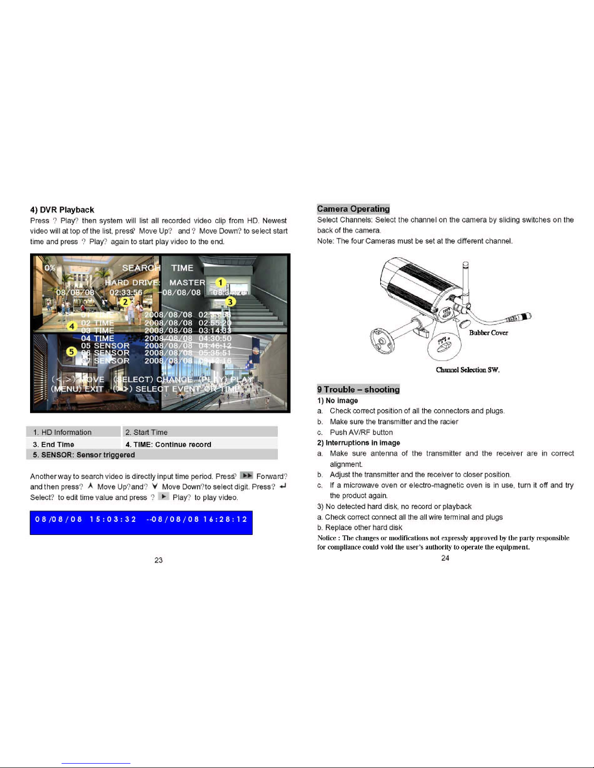
Table of contents
Popular DVR manuals by other brands

HIK VISION
HIK VISION DS-9600NI-ST Series Quick operation guide

Speco
Speco DVR-DS4TN Specifications

American Dynamics
American Dynamics Intellex Intellex LT Reference and troubleshooting guide

Swann
Swann ThumbCam DVR-415 operating instructions

REI
REI HD6-600 Maintenance Guide

LevelOne
LevelOne NVR-0204 user manual


