JFL Alarmes SMARTCLOUD 18 User manual

www.jfl.com.br
User
Manual
JFL
SMARTCLOUD 18
ALARM CENTRAL
Congratulations,
You ha e just acquired a product with JFL Alarmes quality, produced in Brazil with the highest
manufacturing technology. This manual shows all the functions of the equipment.

www.jfl.com.br
ÍNDICE
1 FRONT PANEL:........................................................................................................................................................................3
2 PROGRAMMING OF WIRELESS SENSORS AND REMOTE CONTROLS...........................................................................3
3 PROGRAMMING OF THE BUS SENSORS.............................................................................................................................4
4 ARMING AND DISARMING OF THE CENTRAL UNIT...........................................................................................................5
5 ENABLE AND DISABLE THE DIVIDED MODE.......................................................................................................................6
6 ENABLE AND DISABLE THE CONTINUOUS OR INTERRUPTED TRIGGERING.................................................................6
7 PANIC BY REMOTE CONTROL...............................................................................................................................................7
8 PROGRAMMING MODE.........................................................................................................................................................7
9 AUTOMATIC REARMING AFTER DISARMING.....................................................................................................................7
10 PROGRAMMING OF THE ARM AND DISARM BEEP........................................................................................................7
11 PROGRAMMING OF THE SIREN TRIGGER TIME..............................................................................................................7
12 AUTOMATIC ARMING FOR LACK OF MOVEMENT............................................................................................................8
13 PROGRAMMING OF THE ZONES........................................................................................................................................8
14 RESET OF THE CENTRAL UNIT............................................................................................................................................8
15 INSTALLATION......................................................................................................................................................................9
16 TECHNICAL CHARACTERISTICS.........................................................................................................................................9
17 DEVICE PARTS...................................................................................................................................................................10
18 CONNECTION SCHEME.....................................................................................................................................................11
19 CONNECTION WITH THE CLOUD LINE PROGRAMMER SOFTWARE...........................................................................11
20 INTERCONNECTION WITH THE ETHERNET MODULE....................................................................................................12
21 ACCESS THROUGH THE MOBILE APPLICATION (MODULE ME-04 OR HIGHER IS REQUIRED)...............................12
22 INTERCONNECTION WITH THE JFL ENERGIZER............................................................................................................13
23 INTERCONNECTION OF THE PGM MODULE (OPTIONAL NOT INCLUDED)..........................................................................14

www.jfl.com.br
1FRONT PANEL:
Rede/Bateria LED: Indicates the power supply of the de ice. Green means connected to the AC
network, while yellow means connected to the bateria.
Zona 1 LED / Zona 2 LED: Indicates the current state of zones 1 and 2, with the following
characteristics:
•Off indicates a disabled zone.
•On indicates an enabled zone with closed sensors.
•Flashing quickly indicates an enabled zone with an open sensor.
•Flashing slowly indicates the triggering of the zone. To reset the triggered zones, arm the
central unit again.
Barramento LED: Indicates the state of the bus zones. Flashing quickly indicates an open
sensor; flashing slowly indicates a zone triggering; on indicates closed sensors. To identify an
open or triggered zone, it is necessary to access the central unit through the application using
the ME-04 module or to connect the central unit to the programmer software and isualize the
iolated zone on the screen.
Armado LED: On indicates that the central unit is acti ated.
Obs.: When the barramento LED is off, it indicates that no bus sensor is programmed. To
program the bus sensors, check item 3.
2PROGRAMMING OF WIRELESS SENSORS AND REMOTE
CONTROLS
This central unit accepts opening sensors and wireless infrared sensors, both at the 433.92 MHz
frequency in the Hopping Code system. It recognizes remote controls in the Hopping Code and
Rolling Code systems, both on the 433.92 MHz frequency. To program, press and release the
APRENDER button located on the central unit board and then trigger an opening sensor, infrared
sensor, or remote control. The APRENDER LED turns on for 2 seconds, confirming the recording.
Obs.:
-Each button of the remote control must be programmed.
-The maximum number of controls or sensors is 38.
-The sensor's zone jumper must be at position 1 or 2.
-To erase the memory, press and hold the APRENDER button for 7 seconds until the
APRENDER LED turns off; with this, all the sensors and remote controls will be erased.
-When recording a remote control or sensor, when the memory is full, it will be recorded by
rewriting the 1st memory position.
3

www.jfl.com.br
3PROGRAMMING OF THE BUS SENSORS
The JFL SmartCloud 18 central unit offers the bus technology, which allows increasing the
sector capacity using only one pair of wires. It is possible to add 18 bus de ices, with 16 being
sensors and 2, sirens. The operation zones of the sensors may be sequential or random,
allowing the recording of 16 sensors in one zone or one sensor per zone. To program them, it
is necessary to connect the de ice to the bus, interconnecting them on the - BUS + terminals.
Infrared and opening sensors are powered by the bus itself. In the case of the siren, it is
necessary also to use an auxiliary source (figure below).
After connecting the de ices to the bus, their LEDs remain flashing while they are not learned
and recognized by the central unit. When recognized, the LEDs turn off and only turn on in
case of motion detection (sensors) or when there is a triggering of the central unit (siren).
Each de ice has a serial number engra ed on a tag, used to register the de ice on the central
unit. There are two ways of programming these de ices: con entional method or serial
method. The con entional method uses resources of the central unit itself (remote control
and programar button), while the serial method uses the Cloud line programmer software.
Below, we ha e the procedure for each one.
-Con entional method:
1-With the de ices connected, turn on the central unit and await its initialization;
2-Once the bus is initialized, the recorded de ices flash the LED waiting to be recognized by
the central unit, while the non-registered sensors flash the LED waiting to be learned;
3-Press and release the programar button, then trigger the tamper for the infrared sensor or
mo e away the magnet for an opening sensor. At this moment, the sensor sends a
communication to the central unit, informing its serial number. The central unit detects the
serial number and issues a beep of the siren (SIR out);
4-At this moment, the central unit waits for the user to define the type of zone and the area
of operation (see item 5). With a recorded remote control, press and release one of the
buttons to define the operation area. Next, with the same button, chose the zone type by
following the signaling of the barramento LED (table below). For each transmission of the
remote control, the central unit issues a beep of the siren (SIR out) and alters the signaling of
the barramento LED.
4

www.jfl.com.br
5-To finalize the recording of the bus sensor, press and release the programar button (the
central unit issues 2 beeps of the siren).
6-To program the bus siren, press and release the programar button. Next, approximate a
magnet to the siren according to the image on the side. The bus siren issues a beep, and the
central unit detects the serial number of the de ice and confirms with 2 beeps of the siren (SIR
out).
7-To erase the de ices, enter the programming mode (item 8). Press and hold the aprender
button for 7 seconds until the LED turns off. Release the aprender key; the central unit issues 2
beeps of the siren (SIR out) and erases all de ices recorded on the memory.
See item 13.
** To enable the di ided mode, see item 5.
Obs.:
• The sensiti ity of the bus sensors in the con entional mode is medium (02). To change it,
it is necessary to access the central unit through the Cloud line programmer software
(serial method).
The operation zone of each bus de ice in the con entional mode is sequential, i.e., the 1st
sensor recorded represents zone 3, the 2nd sensor recorded, zone 4, successi ely, with the
same for the bus siren.
-Serial method:
1-Download the Cloud line programmer software and the dri er of the programmer cable from
the website www.jfl.com.br and install them on the computer.
2-Open the Cloud line programmer and follow the instructions of the HELP field to connect the
central unit.
3-When the bus is initialized, the recorded de ices flash the LEDs waiting to be recognized by
the central unit, while the non-registered sensors flash the LED waiting to be learned.
4-Access the "bus de ices" field and register them by typing the serial number of each sensor
or siren and send the programming.
5-Verify the initialization of the de ices.
4ARMING AND DISARMING OF THE CENTRAL UNIT
There are three ways to arm and disarm the central unit: by remote control, through the on inlet,
and through the application.
Remote Control: Press and release a programmed button of the remote control; with this, the
armado LED turns on, and the siren* issues 2 beeps indicating that the central unit is armed.
After the armed central unit signaling, two more short beeps may occur. This signaling indicates
a problem has been detected: either the low battery of a wireless de ice (sensor or remote
control), lack of electric power (BATTERY LED), or a bus sensor super ision issue. To isualize
5

www.jfl.com.br
which de ice has a problem, connect the programmer software to the central unit and
isualize on the monitor screen, or access through the application with the use of the ME-04
Ethernet module. To disarm the central unit, press and release a programmed button of the
remote control; with this, the armado LED turns off, and the siren issues 1 beep indicating
the disarming. In case the central unit detects the occurrence of a trigger in some zone, the
siren issues 2 more short beeps signaling the iolated zone.
Through the on inlet: Apply a pulse without retention on the push button interconnected
between the on and - terminals (item 18).
Via application: Check item "access ia application to the central unit" (item 21).
Obs.: * - The siren only issues an arming and disarming signaling if it is programmed (see
item 10).
- The bus siren does not signal arming and disarming.
5ENABLE AND DISABLE THE DIVIDED MODE
The Di ided Mode, when enabled, allows the user to arm and disarm the zones of the central
unit separately according to the zone programming. Zones programmed as being of area 1
are controlled by button 1 of the remote control, while those as area 2 are controlled by
button 2. Button 3 arms/disarms all zones. With the central unit disarmed, press and release
the programar button and then press and hold button 1 of the remote control for 4 seconds.
The siren issues 2 short beeps when it enables the di ided mode, or 1 short beep when it
disabled it.
Obs.: - Button 1 of the remote control must be programmed.
- Zone 1 is controlled by button 1 and zone 2 is controlled by button 2.
6ENABLE AND DISABLE THE CONTINUOUS OR
INTERRUPTED TRIGGERING
Continuous mode triggering: The central unit triggers the siren when a zone remains open.
Interrupted mode triggering: The central unit triggers the siren only once, while the zone
remains open. When the zone is restored, the central resumes normal operation.
With the central unit disarmed, press and release the programar button, then press and hold
button 2 of the remote control for 4 seconds. The siren issues 2 short beeps when it enables
the interrupted triggering, or 1 short beep when it enables the continuous triggering.
Obs.: - Button 2 of the remote control must be programmed.
- This function is only alid for wired zones (zone 1 and zone 2).
6

www.jfl.com.br
7 PANIC BY REMOTE CONTROL
Press and hold button 3 of the remote control for 4 seconds. The PGM relay triggers for 6
seconds, then deacti ates.
Obs.: - Button 3 of the remote control must be programmed.
- The PGM must be programmed to work along with the SIR out.
8 PROGRAMMING MODE
With the central unit disarmed, press and hold the programar button until the programar LED
turns off. Release the program button and the LED starts flashing, signaling the programming
mode. To exit, press and hold the programar button until the LED stops flashing.
9 AUTOMATIC REARMING AFTER DISARMING
This function enables the automatic arming of the central unit 45 seconds after the disarming in
case there is no iolation of an enabled sector. This resource a oids random disarming due to
accidental touching of the remote control buttons or e en children playing with the remote. To
program, follow the instructions below:
With the central unit in the programming mode, press and hold button 1 of the remote control
for 4 seconds. Two beeps of the siren indicate the rearming is enabled, while 1 beep of the siren
indicates the automatic rearming is disabled.
Obs.: - Button 1 of the remote control must be programmed.
- There is no automatic rearming if the central is disarmed when the siren is ringing.
10 PROGRAMMING OF THE ARM AND DISARM BEEP
This function allows the central unit to issue beeps of the siren when arming and disarming. To
program, follow the instruction below:
With the central unit in the programming mode, press and hold button 2 of the remote control
for 4 seconds. Two beeps of the siren indicate that the arm/disarm beep is enabled, while 1
beep of the siren indicates that the beep is disabled.
Obs.: - Button 2 of the remote control must be programmed.
11 PROGRAMMING OF THE SIREN TRIGGER TIME
With the central unit in the programming mode, press and hold button 3 of the remote control
for 4 seconds. One beep of the siren indicates a trigger time of 1 minute, while 2 beeps of the
siren indicate a trigger time of 5 minutes (Default).
Obs.: - Button 3 of the remote control must be programmed.
- By accessing the Cloud line programmer software, it is possible to change the time from
1 to 255 minutes.
7

www.jfl.com.br
12 AUTOMATIC ARMING FOR LACK OF MOVEMENT
This function allows the central unit to automatically arm due to lack of mo ement in the
premises. To program, follow the instruction below:
With the central unit in the programming mode, press and release button 3 of the remote
control; the ARMADO LED will indicate the programming:
ARMADO LED off: The automatic arming is disabled.
ARMADO LED flashing: The automatic arming is programmed for 30 minutes.
ARMADO LED on: The automatic arming is programmed for 2 hours.
Obs.: - Button 3 of the remote control must be programmed.
- By accessing the Cloud line programmer software, it is possible to change the time
from 1 to 255 minutes.
13 PROGRAMMING OF THE ZONES
To isualize the zone programming, just enter the programming mode. Then, the ZONA1 and
ZONA2 LEDs indicate their respecti e programmings.
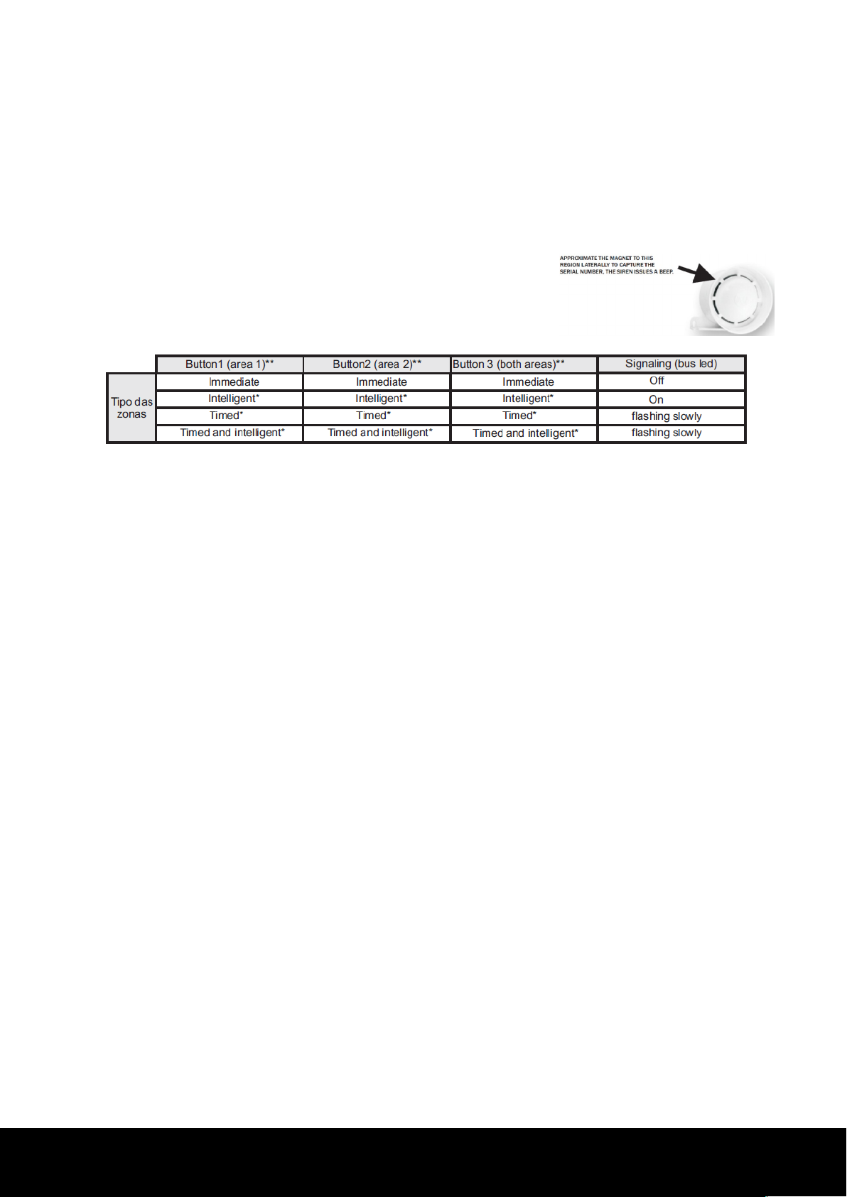
Immediate zone (zone LED off) – When there is a iolation, the siren triggering is immediate.
Intelligent zone (zone LED on) - There must be two iolations in the same zone within the
programmed time* for there to be a trigger. Wireless sensors do not obey the intelligent zone.
Timed zone (zone LED flashing slowly) – Upon arming the central unit, the user has an exit
time of 1 minute to lea e the premises without triggering the central unit, and an entry time
of 1 minute to enter the premises and disarm the alarm without ringing the siren.
Timed and intelligent zone (zone LED flashing quickly) – A zone with entry and exit time
counting, requiring two iolations to being counting the entry time.
To change the zone programming, follow the steps below: 1- Place the central unit in the
programming mode.
2- Press and release the remote control button referring to the zone to be programmed
(button 1 refers to zone 1, and button 2, to zone 2). The siren issues 1 beep, and the LED
referring to the zone changes states (turns off, turns on, flashes slowly, or flashes quickly).
Obs.: * The default time for the intelligent zone is of 1 minute.
- The remote control button must be programmed.
- By accessing the Cloud line programmer software, it is possible to change the entry
time, exit time, and intelligent zone time.
14 RESET OF THE CENTRAL UNIT
There are two ways to reset the alarm central unit.
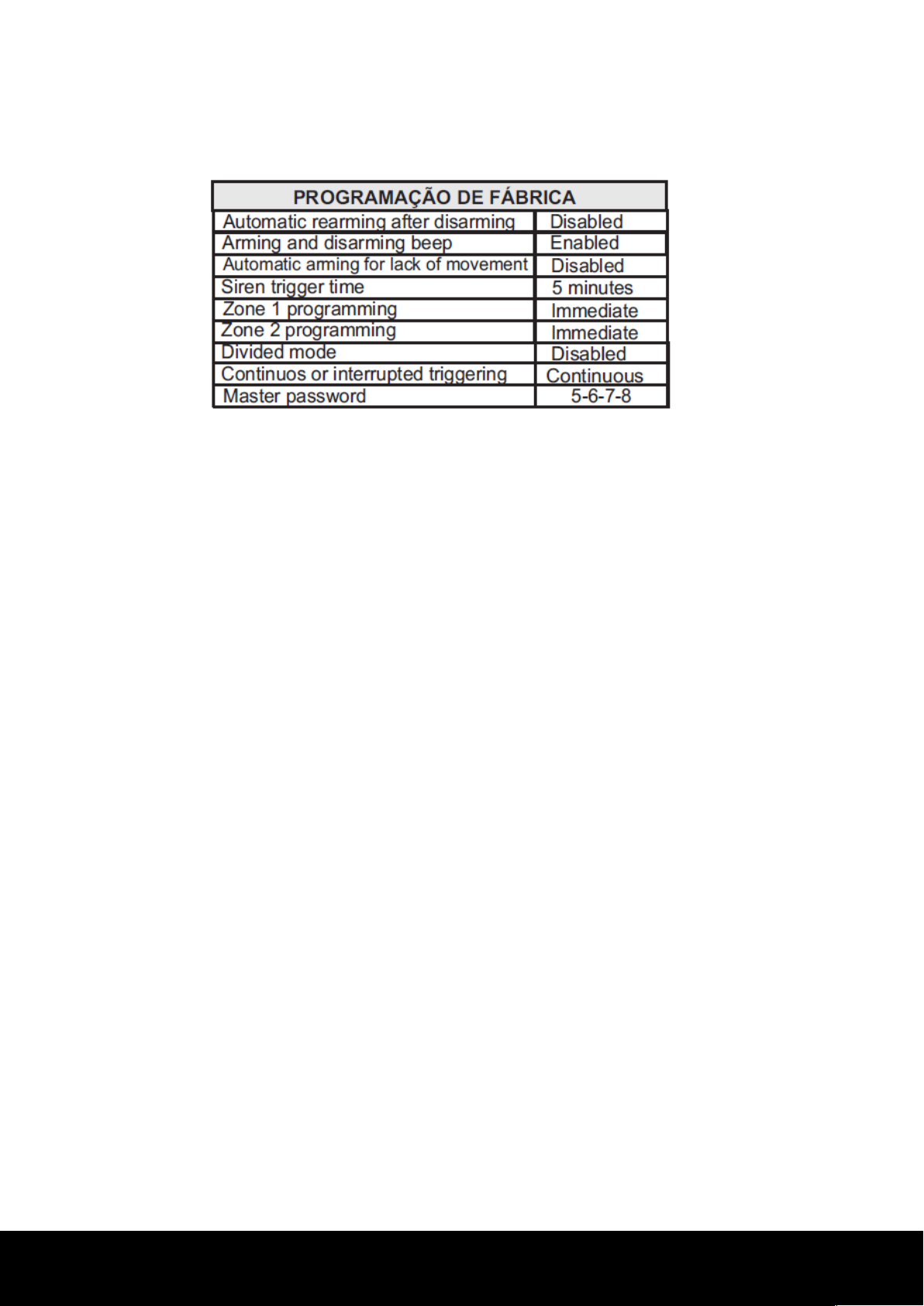
-Partial reset: Erases the master password. Hence, the master password will be 5-6-7-8.
This reset does not affect the other programmings.
-Total reset: Erases all the system programmings and sa es the factory programmings.
To reset the alarm central unit, follow the steps below:
1-Turn off the battery and network powering and wait 10 seconds.
2-Press and hold the aprender button, then turn on the product. The central unit turns
on the REDE/BATERIA LED and starts flashing the aprender LED.
8

www.jfl.com.br
3-For a partial reset, release the aprender button while the LED is flashing (from 0 to 5
seconds).
4-For a total reset, release the aprender button only when the LED stops flashing (time of 10 seconds). Obs.: The
reset does not erase the memory of the remote controls, wireless sensors, and bus sensors.
15 INSTALLATION
To install the central unit, choose a discrete location, out of the iew of strange persons, and
attach it to the wall. All the wiring used for the installation of sensors and sirens must be welded
on the splices.
To install the sensors on doors and windows, one must take care that the distance between the
magnet and the sensor does not surpass 5 mm. When installing an infrared sensor, erify if the
location does not ha e an opening through which animals may enter, gi en triggers may occur.
The infrared sensor must not be installed facing glass doors and walls, plants such as ferns, and
locations with great air circulation.
16 TECHNICAL CHARACTERISTICS
-Supply Voltage: 127/220 Vc.a. - 60 Hz - 12 Vc.c. Battery
-Consumption: 5 W equi alent to 3.6 kWh /month (Obs.: The consumption may reach 10 W
in case the battery is discharged)
-Battery charger oltage: 13.8 Vc.c. +or- 10%
-Dimensions: 295 x 235 x 120 mm
-Gross weight (without battery): 1 Kg
-Maximum current supplied by the siren out (SIR): 200 mA
-Maximum current supplied by the siren out + auxiliary out: 300 mA
-Maximum current supplied by the PGM: 12 Vc.c. / 3 A or 127/220 Vc.a. / 2 A
-Maximum load: 12 Vc.c./ 3 A or 127-220 Vc.a. / 2 A.
-It is recommended the use of a sealed 12 Vc.c. / 7 Ah battery for powering in the lack of
electrical power (does not accompany the central unit).
9

www.jfl.com.br
17 DEVICE PARTS
1- 433.92 MHz recei er antenna.
2-APRENDER button for programming the wireless sensor and remote control.
3-PROGRAMAR button to program the central unit and aprender bus de ices.
4-AC: Transformer input (12 VAC).
5-Battery: Input connector for a 12 V / 7 A battery.
6-+B: Positi e battery out.
7-PGM: Auxiliary out normally open for dry contact.
Maximum load: 12 Vc.c. / 3 A or 127-220 Vc.a. / 2 A.
8-(+/-): VDC out for powering the alarm accessories.
OBS: Capacity of 0.2 A.
9-SIR: Out for triggering the siren; may be connected to 1 piezoelectric siren only.
10-Z1 and Z2: Zone inputs for the connection of wired sensors.
11-LED: LED out for indicating if the alarm is armed or disarmed (maximum current of
20 mA).
12-ON: Input for arming and disarming the central unit through a negati e pulse (see
item 18).
13-( - BUS +): Input of the bus sensors.
14-ETH: Input for the ME-04 Ethernet module or higher (see item 20).
15-PGM module out: Input for the MPG4 module (see item 23).
OBS: To enable the PGM module, it is necessary to program the central unit through
the programmer software.
10

www.jfl.com.br
18 CONNECTION SCHEME
Obs.: - For installations with greater wiring distances, it is recommended to pass a wire of larger
gauge as the bus.
-For the installation of the bus sensors, use wiring with AWG26 (0.2 mm) gauge for a distance of
up to 100 m or a minimum gauge of 0.5 mm2 for up to 200 m between the central unit and the
last sensor, pro ided the wire resistance does not surpass 20 U. To measure the resistance of
the wiring, place a short-circuit in one of the ends and measure the resistance at the other wire
extremity. To reduce the wiring resistance of a 4-way cable, one may place each pair of wires in
short-circuit, thus forming a 2-way cable.
19 CONNECTION WITH THE CLOUD LINE PROGRAMMER
SOFTWARE
11

www.jfl.com.br
1-Download the Cloud line programming software and the programming cable dri er
from our website www.jfl.com.br and install on the computer. Or look for the JFL
Programmer APP on the store and install it on your smartphone.
1-Open the Cloud line programmer and follow the instructions of the HELP field to
connect the central unit.
20 INTERCONNECTION WITH THE ETHERNET MODULE
1 - Break the RJ-45 connector passage on the left side of the box.
2 – Fit the Eternet module to the comportment obser ing the guide on the sides.
3 – Connect the module harness to the ETH connector og the central unit.
Obs.: The Ethernet module already comes with the DHCP function enabled. In case you need
to change the programming of the module or central unit, connect the JFL programmer cable
and access the Cloud line programmer software.
For connecting the Ethernet module with the cloud ser er, the network point must not contain any enabled
security de ices (FIREWALL).
21 ACCESS THROUGH THE MOBILE APPLICATION (MODULE ME-
04 OR HIGHER IS REQUIRED)
This central unit may be accessed directly through the “Acti e Mobile” mobile application,
through the Ethernet module. There are two user types: the administrator and the linked
users. The administrator user is the first user that registers in the central unit, ha ing total
control of the central unit for the functions of arming/disarming, enabling/disabling the
PGM, isualizing the statuses of the zones, ground plan, and inhibit zones. The linked users
may ha e restrictions on such functions according to the permissions gi en by the
administrator user. Follow the instructions for registering a user.
12

www.jfl.com.br
•Download the Acti e Mobile application from the irtual app store and install it on your
Smartphone.
•Open the application and await the initialization.
•Add a new central unit.
•Connect the application to the central unit.
•When connected, it will be possible to arm/disarm, enable/disable the PGM, and erify
triggers in real-time.
Obs.: To erase the central unit’s registry on the cloud, press the “PROG” button of the Ethernet
module for 7 seconds. Upon erasing the central unit’s record from the cloud, all users
registered for this central unit will be excluded.
The JFL SmartCloud-18 central unit ersion 2.0 uses the Acti e Mobile V3 application and the
ME-04 module.
The Acti e Mobile V3 application brings arious no elties for the user:
•Integration of the CFTV system, alarm, and energizer in the same application;
•Notification categories;
•Allows personalizing a sound for each category;
•Allows choosing which category one wishes to recei e;
•Siren sounds upon triggering of up to 30 seconds;
•Groups the notifications from the same location.
22 INTERCONNECTION WITH THE JFL ENERGIZER
1- Connect the energizer to the JFL SmartCloud 18 central unit according to the figure abo e.
13

www.jfl.com.br
2-Connect the central to the Cloud line programmer software (item 19) and program the
PGM field as “Energizer function”; automatically, the Z1 terminal will be configured as
“Energizer trigger” and the Z2 as “Arming/disarming of the energizer”.
Obs.: For the functioning of the “energizer function”, the programming of zones 1 and 2
cannot be disabled. Jumpers J1 and J2 must be remo ed.
23 INTERCONNECTION OF THE PGM MODULE (OPTIONAL NOT
INCLUDED)
Secure the PGM module with screws at the back of the box (outer side).
Break the wire passage, cross the harness of the PGM module, and connect to the central
unit (PGM connector).
Obs.: For the functioning of the PGM module, it is necessary to program the central unit
through the Cloud line programmer software.
14

www.jfl.com.br
PRECAUTIONS:
Do not try to adjust or modify the de ice.
•Maintenance may only be performed by persons indicated by JFL.
•The de ice owner must test the sensors at least once a week to be sure that the batteries are
good for the sensors to work properly when iolated.
FOR BEING A SAFETY AND SENSIBLE-ADJUSTMENT EQUIPMENT, IT MUST BE INSTALLED BY
SPECIALIZED AND EXPERIENCED TECHNICAL PERSONS.
.
15

www.jfl.com.br
16
WARRANTY
JFL Equipamentos Eletrônicos Indústria e Comércio Ltda warrants this de ice for a period of 12
months from the date of purchase, against manufacturing defects that pre ent its operation
within the specified technical characteristics of the product. During the warranty period, JFL
will repair (or replace, at its sole discretion), any defecti e components.
The warranty excludes defects caused by:
-Installation out of the technical standard specified in this manual;
-Improper use;
-Equipment iolation;
-Atmospheric and accidental phenomena.
The isit of a technical person to a different location will depend on the express authorization of
the client, who will bear the expenses resulting from the trip, or the de ice will be returned to the
selling company for repair.
JFL EQUIPAMENTOS ELETRÔNICOS IND. COM. LTDA
Rua João Mota, 471 - Jardim das Palmeiras
CEP 37.540-000 - Santa Rita do Sapucaí / MG
Fone: (35) 3473-3550 / Fax: (35) 3473-3571
www.jfl.com.br
1.8.522 - Central de Alarme JFL SmartCloud 18 - Inglês rev. 05 17/02/20
Table of contents
Popular Security System manuals by other brands

patura
patura 15631 Mounting instructions

Bosch
Bosch Plena Power Amplifier Installation and user instruction manual

Paso
Paso C57/6-EN instruction sheet

Protector Security Group
Protector Security Group The Protector owner's manual

Defender
Defender SN502-4CH quick start guide

Sargent
Sargent Stinger 310 Operation and installation manual