JHJX JHM05 Instructions for use

0
SAFETY INSTRUCTIONS AND MAINTENANCE MANUAL FOR
JHM05 HYDRAULIC TORQUE WRENCES
It is operating manual of JHM05 wrenches, please read carefully follow instructions. Warnings
and cautions before using the tools.

Hydraulic Torque Wrench Operation and Maintenance Manual
1
Ⅰ SECURITY GUIDE
Special emphasis: JHJX hydraulic torque wrench is the power tool for any power tool,
indeed, a reliable security prevention are very important, the following is important to
note a few suggestions.
●Read all the technical documents.
●Try to make the working environment clean and bright.
If the environment in the workplace air explosion could have any potential, you may
not use electric pumps, pneumatic pumps should be used. If metal crash sparks,
should take preventive measures.
●Reaction arm
Hydraulic wrench operation requires proper reaction fulcrum, according to the site
need to adjust the reaction arm or the appropriate reaction arm position. If still not
working, please consult the JHJX.
●To avoid the tools (hydraulic wrench) misuse
Pumps operate the remote control just for the wrench to use, to avoid separating the
operator and the pump is too far.

Hydraulic Torque Wrench Operation and Maintenance Manual
2
●Ensure operation of space
Hydraulic wrench is not in use most of the hand, if you must use the hand or in the
case of the fixed wrench, should think of other ways to achieve their goals.
●Avoid electric shock
With electric pump to ensure a good grounding and proper power supply voltage.
●Hydraulic wrench should be saved without good
Temporarily unused hydraulic wrench and wrench accessories should be properly
stored to avoid damage.
●Using the appropriate hydraulic wrench
Not with a small torque wrench or hydraulic accessories to replace the hydraulic
torque wrench work, not unsuitable to work the hydraulic wrench.
●Wear appropriate labor protection products
When using the manual / motorized hydraulic equipment, you should use gloves,
helmets, safety shoes, ear protection, labor insurance and other protective clothing.
●Safety glasses
●Mobile Devices
Do not drag through the hydraulic tubing, rotary joints, hydraulic power cord or
external cables, etc. to move the unit. Hydraulic wrench comes with handles, can be
used to move equipment.
●High-pressure tubing
Do not bend, fold tubing, always check the tubing, if damaged, should be replaced.
●Dust cover and side cover
All tools have dust cover and side cover, so that internal moving parts and the
separation of the external environment, in addition to JHJX professional
maintenance staff, users do not want to disassemble or use tools without guards.
●Careful to maintain the hydraulic wrench
To ensure the best performance tool, should always check the tool itself, the power
source, tubing, quick connectors, wires, attachments to prevent some common
damage occurs. Should be in the proper hydraulic wrench, hydraulic pump unit to
repair the maintenance guide.
More detailed maintenance instructions please refer to maintenance section.
●Vigilance
To maintain attention at work, can not be used in an unstable state of power
equipment.

Hydraulic Torque Wrench Operation and Maintenance Manual
3
●Preparation before operation
Ensure that all hydraulic couplings are indeed connected. Check the hydraulic
tubing is not entangled, to determine the square head drive shaft and maintain the
cap is secure, reliable joint then. Ensure that all connectors, elbows, swivels
without distortion or damage.
●Preparation before use
Rotate the drive shaft of hydraulic wrench square head is observed with good
function. Looking for a fixed surface, choose a good spot, make sure the reaction
arm to support reliable, to ensure that the hydraulic tubing is not suppressed.
System pressure, if the hydraulic wrench beating or shaking, stop and then
re-adjust the reaction arm and the anchor, to make it more solid and safe.
Note: The operation, reaction arm should be kept clean, and the role of
anti-surface between the arms cannot have a foreign body.
●Please stick with quality accessories
Use high strength sleeve because the sleeve has the exact size of high-quality, and
nuts are a good match. Hidden crack has the potential to rupture the sleeve in use,
so proper maintenance of the sleeve, the sleeve in operation to keep clean and
manipulation.
Do not use force, but do not use a hammer sleeve, as well as tools to increase the
force, if you are not using a hydraulic wrench turn the nut, use a larger device JHJX
hydraulic wrench.
Note: JHJX designed only to drive the hydraulic pump JHJX hydraulic wrench;
improper use may cause damage to the hydraulic pump or hydraulic
wrench.

Hydraulic Torque Wrench Operation and Maintenance Manual
4
WARNINGS
Write tips (box checked)
Carefully check the product for damage. If you find that due to shipping damage,
shall promptly report to the freight operators; shipping damage is not included in
the quality assurance within the freight business has the responsibility to bear
the cost of repair or replacement items.
Security Alert
High pressure hydraulic torque wrench is a tool that should be read carefully
before using all of the instructions, warnings and precautions, comply with
safety measures to avoid when operating the equipment or personal injury or
equipment damage! JHJX for operation and error operation because of
insecurity due to equipment damage and personal injury irresponsible!
Ⅱ OPERATING DIRECTIONS FOR USE
One:DESCRIPTION
The material of JHM05 Hydraulic Torque Wrenches are Aluminium-Titanium alloy and super high strength
alloy steel for increased strength, intensity and durability of the tool. High repeatability, a precise design is
with accuracy ±3%.
1、JHM05, Square Drive Torque Wrenches:
FLG 1
ITEM NAME
①BODY
②3600×1800SWIVELJOINT
③QUICK COUPLING
④FIXING HOOK
⑤3600SWIVELREACTIONARM
⑥SQUARE DRIVE
⑦DRIVE RETAINER
⑧QUICK RELEASE ARM

Hydraulic Torque Wrench Operation and Maintenance Manual
5
TWO: WARNING AND CAUTION
WARNING
To avoid personal injury and equipment damages, be sure that every hydraulic component can rated for
10,000PSI (700kg/㎝ 2)Operating Pressure.
WARNING
Try to minimum the danger of overload: Using hydraulic gauge to indicate the working pressure. Hydraulic
gauge is a window to show what happened in the hydraulic system.
WARNING
To replace the worn components with the JHJX’s new components as soon as possible.
CAUTION
Do not subject the components to potential hazard such as fire, sharp surfaces, extreme heat or cold, or
heave impact.
CAUTION
Never attempt to grasp a leaking pressurized hose with your hands. The force of escaping hydraulic fluid
could cause serious injury.
Do not let the hose kink, twist, curl or bend so tightly that oil flow within the hose is blocked or reduced.
Do not use the hose to move attached equipment. Stress can damage the hose, causing personal injury.
WARNING
To avoid personal injuries and equipment damages, do not remove the shroud of the wrench.
Do not modify any component of the wrench. Do not change the relief valve which is inside the swivel
couplings.
CAUTION
The incorrect system connection will cause failure and danger. Before connection, make sure the swivel
couplings being clean.After application, the swivel couplings must be put on the dust caps.
CAUTION
Do not use worn socket and square drive.
CAUTION
Please use the socket of good performance. The quality should be according with the standard of ISO-2725
or ISO-1174 or DIN3129 or DIN3121 or ASME-B107.2/1995.

Hydraulic Torque Wrench Operation and Maintenance Manual
6
Three: BOLTING TIGHTENING FORCE RECOMMENTED CHART
The belows are DIN (For you reference) FORM1
Strength Grade 4.8 6.8 8.8 10.9 12.9
Min breaking strength 392MPa 588MPa 784MPa 941MPa 1176MPa
Material Q235(SS41) 35(S35C) 35CrMo(SCM3) 42CrMo(SCM4) 40GrNiMoA(SNCM)
Bolting Thread Torque Torque Torque Torque Torque
KGM N.M KGM N.M KGM N.M KGM N.M KGM N.M
M16 24mm 10 98 14 137 21 206 25 247 36 363
18 27 14 137 21 206 29 284 35 341 49 480
20 30 18 176 28 296 41 402 58 569 69 480
22 32 23 225 34 333 55 539 78 765 93 911
24 36 32 314 48 470 70 686 100 981 120 1176
27 41 45 441 65 637 105 1029 150 1472 180 1764
30 46 60 588 90 882 125 1225 200 1962 240 2352
33 50 75 735 115 1127 150 1470 210 2060 250 2450
36 55 100 980 150 1470 180 1764 250 2453 300 2940
39 60 120 1176 180 1764 220 2156 300 2943 370 3626
42 65 155 1519 240 2352 280 2744 390 3826 470 4606
45 70 180 1764 280 2744 320 3136 450 4415 550 5390
48 75 230 2254 350 3430 400 3920 570 5592 680 6664
52 80 280 2744 420 4116 480 4704 670 6573 850 8330
56 85 360 3528 530 5149 610 5978 860 8437 1050 10290
60 90 410 4018 610 5978 790 7742 1100 10791 1350 13230
64 95 510 4998 760 7448 900 8820 1224 11998 1530 14994
68 100 580 5684 870 8526 1100 10780 1392 13645 1740 17053
72 105 660 6468 1000 9800 1290 12642 1584 15527 1980 19405
76 110 750 7350 1100 10780 1500 14700 1800 17644 2250 22050
80 115 830 8143 1250 12250 1850 18130 1992 19547 2489 24429
85 120 900 8820 1400 13720 2250 22050 2160 21172 2699 26459
90 130 1080 10584 1650 16170 2500 24500 2593 25407 3241 31752
100 145 1400 13720 2050 20090 2800 27440 3361 32935 4200 41160
110 155 1670 16366 2550 24990 3340 32732 4009 39287 5010 49098

Hydraulic Torque Wrench Operation and Maintenance Manual
7
120 175 2030 19894 3050 29890 4060 39788 4873 47756 6090 59682
NOTE:
The figure of the chart is the Max torque of the bolting, the recommended torque is 70~80%of chart figure
For instance: M48, strength grade is 8.8, the torque is 3920×80%=3136N.m
Four: OPERATION
CONNECTING THE TOOL
The wrench and power pump are connected by a 700 BAR operating pressure, twin-line hose assembly.
Each end of the hose will have one male and one female connector.
Assure proper interconnection between pump and wrench.
JHM 05
DRIVE DIRECTION CHANGE
To remove the square, disengage the drive retainer assembly by depressing the center round button and
gently pulling on the square end of the square drive. The square drive will slide easily out.
To insert the drive in the tool, place the drive in the desired direction, engage drive and bushing splines,
then twist drive and bushing until ratchet spline can be engaged. Push drive through ratchet. Depress drive
retainer button, engage retainer with drive and release button to lock.
SETTING THE REACTION ARM
All JHJX’s Torque wrenches are equipped with a universal reaction arm. These reaction arms are employed
to absorb and counteract forces created as the unit operates. The reaction arm should extend in the same
lnsure the connectors are fully
engaged and screwed snugly
and completely together.
FLG 4
Right is tight.
Left is loose.
FLG 5

Hydraulic Torque Wrench Operation and Maintenance Manual
8
direction of the square drive; however, slight adjustments may be made to suit your particular application.
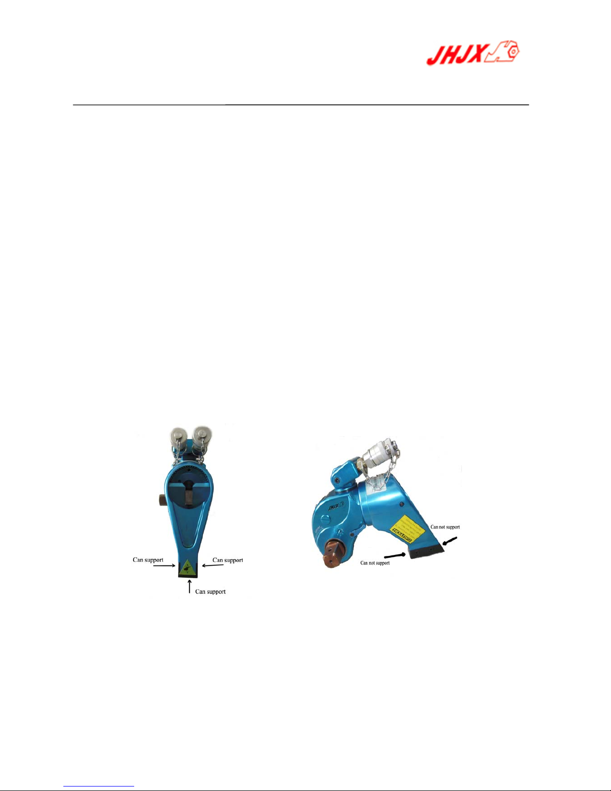
The function of a reaction:
Device is to hold the tool in position against the forces generated to tighten or loosen bolts or nuts. Hydraulic
wrenches generate tremendous force. The reaction arm can be positioned in numerous places within a
3600circle. However, for the arm to be correctly positioned, it must be set within a 900quadrant of that circle.
That quadrant is the area located between the protruding square drive and the bottom of the housing away
from the swivel inlets. It will always be toward the lower half of the housing and on one side of the housing
when tightening and the other side when loosening.
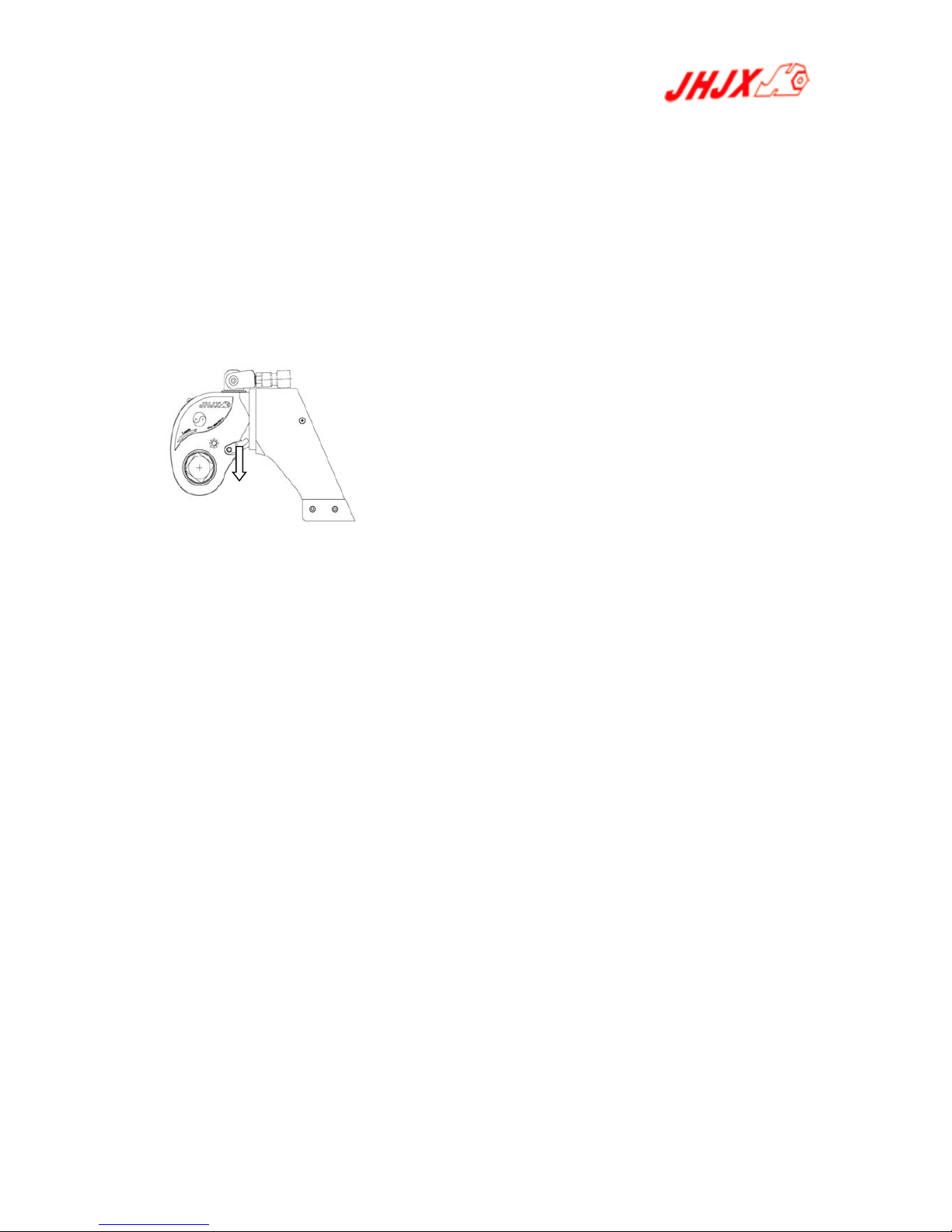
SETTING THE SQUARE DRIVE FOR ROTATION
The position of the square drive when looking toward the shroud will determine if the tool is set to tighten or
loosen the nut. When the square drive extends to the left when looking at the shroud with the inlets away
from you, the tool is set to loosen the nut. When the square drive extends to the right, the tool is set to
tighten the nut. To change the direction of rotation for JHM series wrenches simply push the square drive
into the housing until the drive projects out the opposite side of the tool.
SETTING THE TORQUE
After determining the desired torque, use the torque conversion charts to determine the pressure that is
necessary to achieve that torque.
1. Connect the tool to the power supply and turn the pump on.
2. Depress the advance remote control button causing the pressure to be shown on the gauge.
3. Adjust the pressure by first loosing the nut that locks the pressure adjustment handle and then rotate
the handle clockwise to increase the pressure and counter clockwise to decrease the pressure. When
decreasing pressure, always lower the pressure below the desired point and then bring the pressure
gauge back up to the desired pressure.
4. When the desired pressure is reached, retighten the lock nut and cycle the tool again to confirm that the
desired pressure setting has been obtained.
OPERATING THE WRENCH
1. Place the square Drive in the socket, insert the socket retainer ring and pin, and place the socket to the
nut. Make certain the square drive and socket are the correct size for the nut and that the socket fully
engages the nut.
2. Position the reaction arm against an adjacent nut, flange or solid system component.
Make certain that there is clearance for the hoses and swivel couplings. Do not allow the tool to react
against the hoses, or swivel couplings. When reacting directly off the tool body with reaction arm removed.
Do not react off the exposed end plug spigot.
3. After having turned the pump on and presetting the pressure for the correct torque, depress the remote
control advance button to advance the piston assembly.
4. When the wrench is started, the reaction surface of the wrench or reaction arm will move against the
contact point and the nut will begin to turn. Once the piston reaches the end of its stroke depress the
remote control return button to retract the piston.
FIG 6

Hydraulic Torque Wrench Operation and Maintenance Manual
9
5. Continue this cycling operation of advance and retract until the nut is no longer turning and the pump
gauge reaches the preset pressure. The piston rod will retract when the retract button is pressed and under
normal conditions, an audible “click” will be heard as the tool resets itself.
6. Continue to cycle the tool until it “stalls” and the preset psi/torque has been attained.
7. Once the nut stops rotating, cycle the tool one last time to achieve total torque
CAUTION
During the operation, if the tool locks on to the nut, press advance button on remote and build pressure-continue
to press down on remote while pushing down on the reaction pawl-release remote while continuing to push
down on reaction pawl, then the tool will the released from the nut.
FIG 7
Pulling
down

Hydraulic Torque Wrench Operation and Maintenance Manual
10
Five: Date of JHM05 Hydraulic torque wrench
Date Model JHM05
Min torque(N.m)447
Max torque(N.m)4466
Square drive 1''
L1(mm) 170
L2(mm) 140
L3(mm) 249
H1(mm) 70
H2(mm) 98
H3(mm) 130
H4(mm) 168
R(mm) 37
Weight(Kg) 4

Hydraulic Torque Wrench Operation and Maintenance Manual
11
JHM05 HYDRAULIC TORQUE WRENCH – TORQUE CHART
M
o
d
e
l
Ba
r
JHM05
N·
m
70 447
80 510
90 574
100 638
110 702
120 766
130 829
140 893
150 957
160 1021
170 1085
180 1149
190 1212
200 1276
210 1340
220 1404
230 1468
240 1531
250 1595
260 1659
270 1723
280 1787
290 1850
300 1914
310 1978
320 2042
330 2106
340 2169
350 2233
360 2297
370 2361
380 2425
390 2488
400 2552
410 2616
420 2680
430 2744
440 2808
450 2871
460 2935
470 2999
480 3063
490 3127
500 3190
510 3254
520 3318
530 3382
540 3446
550 3509
560 3573
570 3637
580 3701
590 3765
600 3828
610 3892
620 3956
630 4020
640 4084
650 4147
660 4211
670 4275
680 4339
690 4403
700 4466
TROUBLE SHOOTING GUIDE
TROUBLE PROBABLE CAUSE SOLUTION
Piston will not advance
or retract Couplers are not securely
attached to the tool or pump Check the coupler connections
and make certain that they are

Hydraulic Torque Wrench Operation and Maintenance Manual
12
connected.
Coupler is defective Replace any defective coupler
Defective remote control unit Replace the button and/or
control pendent
Dirt in the direction-consol
valve o the pump unit Disassemble the pump and
clean the direction-control
valve
Piston will not retract Hose connections reversed Make certain the advance on
the pump is connected to the
advance on the tool and retract
on the pump is connected to
the retract on the tool
Retract hose not connected Connect the retrace hose
securely
Retrace pin and/or spring
broken Replace the broken pin and/or
spring
Cylinder will not build up
pressure Piston seal and/or end plug
seal leaking Replace any defective o-ring
Coupler is defective Replace
Square Drive will not turn Grease or dirt build up in the
teeth of the ratchet and
segment pawl
Disassemble the Ratchet and
clean the grease or dirt out of
the teeth
Worn or broken teeth on
ratchet and/or Segment Pawl Replace any worn or damaged
parts
Pump will not build up
pressure Defective relief valve Inspect, adjust or replace the
relief valve
Electric power source is too
low Make certain the amperage,
voltage and any extension aord
size comply with the pump
manual requirements
Defective gauge Replace the Gauge
Low oil level Check and fill the pump
reservoir
Clogged filter Inspect, clean and/or replace
the pump filter
NutReturnwithretract
stroke Ball Plungers are not engaging
the Drive Sleeves Thread the Ball Plungers to the
correct depth in the Housing
This manual suits for next models
1
Table of contents
Popular Power Tools manuals by other brands

Stanley
Stanley Avdel STD Genesis nG3LB Tool Instruction manual supplement

Raider
Raider Pro RDP-SCG20 solo Original instruction manual

Flexco
Flexco Alligator Ready Set RSC187 Training manual

Holzmann
Holzmann SB162VN 230V user manual

Hilti
Hilti SC 70W-A22 operating instructions

Fein
Fein QSz 636-1 operating instructions